Form WA004, Page 4
Units should always be arranged to blow toward or along exposed
wall surfaces, if possible. Where two or more units are installed in
the same room, a general scheme of air circulation should be main-
tained for best results.
Suspended heaters are most effective when located as close to the
working zone as possible. However, care should be exercised to
avoid directing the discharge air directly on the room occupants.
Partitions, columns, counters, or other obstructions should be taken
into consideration when locating the unit heater so that a minimum
quantity of air will be deflected by any such obstacles. When units
are suspended in the centre of the space to be heated, the air should
be discharged along exposed walls. In large areas, unit should be
locatedto dischargeair alongexposed wallswith extraunits provided
to discharge air in toward the centre of the area. At those points
where infiltration of cold air is excessive, such as at entrance doors
and loading doors, it is desirable to locate the unit so it will discharge
directly toward the source of cold air from a distance of 4.5 to 6.0
metres.
3.0 GENERAL REQUIREMENTS
3.1 Related Documents
It is important that all gas appliances are installed by competent
persons, i.e. a registered CORGI installer, in accordance with the
relevant requirements of the following regulations.
Failure to install appliances correctly could lead to prosecution. It is
in your own interest and that of safety to ensure compliance with
the law.
THERELEVANTREGULATIONSARE...
GASSAFETY(INSTALLATIONS&USE)(Amendment)REGU-
LATIONS 1990
THEHEALTHANDSAFETY AT WORK,ETC. ACTS
••
••
•BS6230 1991 SPECIFICATION FOR THE INSTALLATION
OF GAS FIRED FORCED CONVECTION AIR HEATERS
FOR COMMERCIAL AND INDUSTRIAL SPACE HEAT-
ING OF RATED INPUT EXCEEDING 60 KW.
••
••
•BS5588 PART 1 (SECTION 1) 1990; PART 2 1985 AND
1990; AND PART 3 1983 AND 1989
••
••
•BS5440 PART 2 1989 FLUES AND AIR SUPPLY FOR GAS
APPLIANCES NOT EXCEEDING 60 KW
••
••
•BS6891 1988 LOW PRESSURE INSTALLATION PIPES
BRITISHGAS PUBLICATIONS
IGE/UP/1 PURGING PROCEDURES FOR NON-DOMESTIC
INSTALLATIONS and SOUNDNESS TESTING PROCE-
DURES FOR INDUSTRIAL INSTALLATIONS.
I.E.E. REGULATIONS FOR ELECTRICAL INSTALLATIONS
AND THE REQUIREMENTS OF THE FOLLOWING...THE
LOCALREGION OF BRITISHGASPlc
WARNING: Air heaters should not be installed
in corrosive atmospheres, i.e., near plating or
degreasing plants or in areas where there is a
firerisk.ConsultBS6230forfurtherinformation
onhazardousareas.
3.2 Heater Location
The location chosen for the heater must permit the provision of a
satisfactory flue system and an adequate air supply. The location
must also provide space for servicing and air circulation around the
unit.
Table 4 - RequiredClearances (mm)
Sizes Top Flue Sides Bottom Rear Front
25 -
125 152 152 460 610 610 1830
165 -
250 152 152 460 610 610 2440
300 -
400 152 152 460 610 610 3050
For service purposes, rear must have 610 mm clearance. When sup-
plied with optional downturn nozzle, bottom clearance is 1.0 m.
The location should be free of draughts.
WARNING: Avoidinstalling a unitinan extremely
draughty area. Extreme draughts can shorten the
life of the heat exchanger and/or cause safety
problems.
Refer to Table 5 for recommended mounting height for UF Models.
3.3 Flue System
Each heater must be fitted with an adequately sized flue (See Table
6). Stainless steel flue pipe is recommended.
WARNING: The flue must be installed in
accordancewithBS5440Part 11990 forallmodels
up to and including Size 200 or BS6230 1991 for
all Models Size 250 and over.
Failure to provide proper flueing could result in
death,seriousinjuryand/orpropertydamage.The
unit must be installed with a flue to the outside of
thebuilding.Safeoperationofanynaturaldraught
gas burning equipment requires a properly
operating flue system, correct provision for
combustion air, and regular maintenance and
inspection.
The unit heater is fitted with an integral draught diverter. Do not use
an external draught diverter, barometric damper and/or restrictive
damper.
When condensation is possible within the flue, double wall flue pipe
is recommended. When double wall flue pipe is used, it should be a
type complying with British Standards. Double wall flue pipe re-
quires the use of a special flue socket adapter. Where condensation is
unavoidable, provision should be made for condensation to flow
freely to a point at which it can be released, preferably into a gulley.
The condensation pipe from the flue to the disposal point should be
of non-corrodible material, not less than 19 mm diameter.
The flue must terminate outside the building in a freely exposed
position so as to prevent products of combustion from entering any
opening in a building.
If the flue passes through a wall or ceiling of combustible material, it
must be enclosed by a sleeve of non-combustible material and sepa-
rated from the sleeve by at least 25 mm air gap. The temperature of
any combustible material near the flue or heater must not exceed 65o
C when the heater is in operation. The flue must also be at least 50
mm from any other combustible material.
The joint between the female flue socket of the heater and the flue
must be sealed. If twin wall flue piping is used, the appropriate
adapter must be fitted.
The joints between the flue and the roof must be made good to
prevent water ingress.
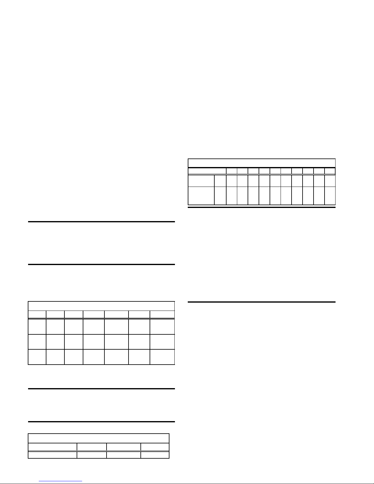
Table 6 - Flue Diameter and Minimum Hei
ht
Size 25 50 75 100 125 165 200 250 300 400
Flue Pipe
Diameter mm 100 100 125 150 175 200 200 250 250 250
Min. Height
of Flue M 1.5 1.5 1.5 1.5 2.0 2.0 2.0 2.0 2.0 2.0
Table 5 - Recommended Mounting Heights
UF Models 25 - 125 165 - 250 300 - 400
Mounting Height 2.5 - 3 m 2.5 - 3.5 m 3 - 5 m