amc VIBRO AV ACQUISITION 4001 User manual

USER MANUAL
2018
AV ACQUISITION 4001
/ ©AMC VIBRO Sp. z
amc VIBRO Sp. z o.o.
ul. Pilotow 2e,
31-462 Krakow, Poland
T: +48 (12) 362 97 60
S: + 48 (12) 362 97 63
info@amcvibro.pl
KRS No.: 0000618618
REGON No.: 364497010
VAT No.: PL6772403385
www.amcvibro.pl
4-CHANNEL DATA ACQUISITION
MODULE WITH GAIN

2
AV ACQUISITION 4001 / ©AMC VIBRO Sp. z o.o.
Table of contents
1. Introduction ...........................................................................................................................................................................3
2. Contents of the package .................................................................................................................................................3
3. Technical data .......................................................................................................................................................................4
4. Measurement accuracy......................................................................................................................................................5
5. Description of connections and status lights ...........................................................................................................7
6. Connection with a computer using Windows 7 ......................................................................................................7
7. InstaCal ....................................................................................................................................................................................8
8. DASYLab® 16 configuration...........................................................................................................................................8
9. Using the AVA 4001 module in DASYLab® 16........................................................................................................9
10. Recycling .........................................................................................................................................................................11
10.1. Hazardous Materials..............................................................................................................................................11
10.2. Recycling Facilities..................................................................................................................................................11

3
AV ACQUISITION 4001 / ©AMC VIBRO Sp. z o.o.
1. Introduction
AV ACQUISITION 4001 (AVA 4001) is a universal, portable 4-channel data acquisition module designed
to operate with IEPE standard sensors. The module has 16-bit resolution and sampling frequency up to
100 kS/s. The provided drivers allow operation with DASYLab®, LabVIEWTM and Matlab®.
Module characteristics:
»operation with four IEPE standard vibration sensors
»sensor circuit functional check –warnings of possible open and short circuits
»communication and power supply from USB port of a connected computer
»smooth installation
»compact dimensions
2. Contents of the package
The package contains:
»AVA 4001 module
»CD with drivers
»suitcase
»USB cable
»manual

4
AV ACQUISITION 4001 / ©AMC VIBRO Sp. z o.o.
3. Technical data
Parameters
Value
Number of channels
4
Inputs
IEPE 2.4 mA 24V
Resolution
16 bit
Sampling frequency
Up to 100 kS/s per channel; combined scan rate for
all active channels is max. 400 kS/s
Measurement range
±10V, ±5V, ±2V i ±1V (selected by software)
Crosstalk
-80 dB (within 0 - 25 kHz band)
Maximum
absolute error
range ±10V
±5.66 mV
range ±5V
±2.98 mV
range ±2V
±1,31 mV
Range ±1V
±0.68 mV
Power supply
5 V DC supplied by the PC USB port, max. current
intake 400 mA
Communication interface
USB 1.1, USB 2.0
Humidity
0..90%, non-condensing
Operating temperature range
0..+70°C
Dimensions
130 x 110 x 40 mm

5
AV ACQUISITION 4001 / ©AMC VIBRO Sp. z o.o.
4. Measurement accuracy
Total measurement accuracy is affected by 3 types of errors:
»Offset
»Gain
»Non-linearity
The main source of errors of the unit is the error related to offset and gain. The non-linearity error is
negligibly small and may be overlooked. The device is equipped with a 16-bit ADC converter, which
transforms analog signals into values ranging from 0 to 65525. The following is an ideal characteristic
for a ±10 V range.
The offset error is measured in the mid-point of the measurement range. In an ideal case, an input signal
of 0V should cause the converter to return the value of 32768. Any other result means an offset error.
For the ± 10 V range, the maximum offset is ± 1.66 mV.

6
AV ACQUISITION 4001 / ©AMC VIBRO Sp. z o.o.
The gain error is related to the difference between the slope of the real characteristics and the ideal
characteristics and is expressed as a percentage. For the ± 10 V range, the gain error is ±0.04%.
Adding the offset and the gain errors produces the device’s total measurement error.

7
AV ACQUISITION 4001 / ©AMC VIBRO Sp. z o.o.
5. Description of connections and status lights
Inputs –BNC inputs used to connect IEPE standard sensors
Sensors Error –red diodes, lighting up indicates open or short
circuit in the marked channel.
Power –red diode, when shining continuously signals, that the
device is connected to the computer and is ready to operate
USB –USB type B plug for connection with a computer
6. Connection with a computer
using Windows 7
AVA 4001 does not require the installation of any
drivers in the operating system. The operating system
detects a new device automatically when connected
and displays it in the hardware manager as a USB HID
interface device. The figure besides presents a correctly detected AVA 4001 module in the hardware
manager of Windows ® 7.
Some computers, especially laptops, may limit power supply to USB devices.
This may result in a fault of the AVA module, e.g. sensor circuit check may
operate incorrectly.
Attention
When connected computer limits power supply to USB devices, the AVA
module may operate incorrectly. Make sure that the computer is able to
supply current of at least 400 mA.

8
AV ACQUISITION 4001 / ©AMC VIBRO Sp. z o.o.
7. InstaCal
To install the InstaCal utility software run the Icalsetup.exe file
located in the /InstaCal/ folder on the supplied CD. The software
will request permission to unpack and to install. Click OK and Setup
in a sequence of windows that will appear to access the installer
window. Then click the Next button twice (without changing the
access path) to confirm that you wish to launch installation and then
click Install.
When installation is complete, click the Finish button to close the
installer window. Restart the computer to apply the changes.
After the restart run the InstaCal software (Start > All programs > Measurement Computing > Instacal)
when the AVA module is connected to the computer. A window will appear with a list of measurement
cards which have been detected. Mark the item named USB-1608FS, click OK and close InstaCal.
The above procedure should be carried out once before using the data acquisition module for the
first time in data acquisition software.
8. DASYLab® 16 configuration
Before starting to work with the AVA module in DASYLab®, it
need to be configured properly in the Configurator (by default:
Start > All programs > DASYLab > Configurator). In the program’s
window, in the Packages tab, the Measurement Computing option
should be marked. If it is not marked, please mark it, and click the
Enable button to launch the installation of drivers in DASYLab®.
In a sequence of windows that will appear, click Next, Next, Install
and Finish respectively.
The above procedure should be carried out only once when
using the module for the first time.

9
AV ACQUISITION 4001 / ©AMC VIBRO Sp. z o.o.
9. Using the AVA 4001 module in DASYLab® 16
After running properly configured DASYLab® software the analog inputs will
be available to the user. The inputs are listed in the following tab: Modules >
Inputs/Outputs > MCC-DRV. The in AVA 4001 module only 4 analog inputs are
available, while remaining 4 analog inputs, the outputs and the counters are not
available.
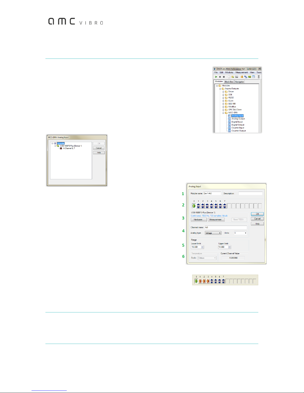
To use an analog input, just drag it inside the worksheet (or you may double-
click it and indicate the module’s position on the worksheet). A window will
appear as shown in the figure below. Mark All Channel 0..7 and confirm your
choice by clicking the OK button.
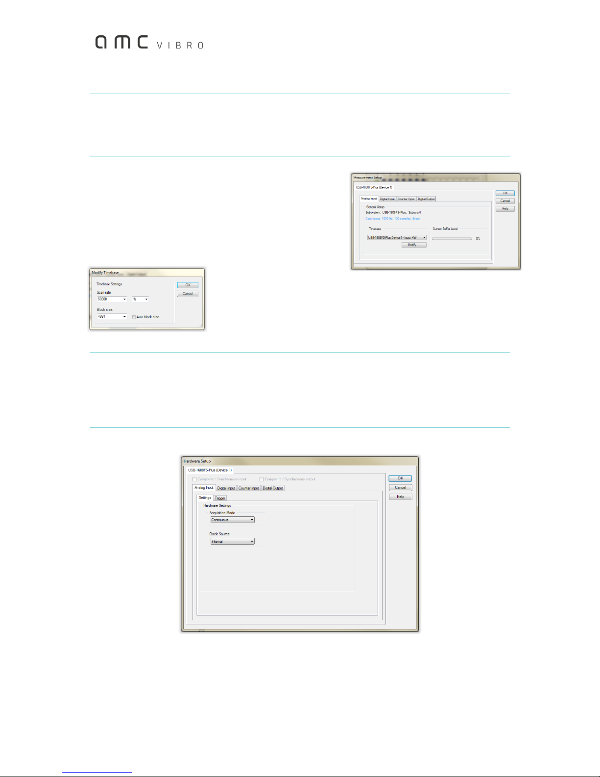
The user can configure the number of active
analog inputs, measurement range separately for each channel as well
as the sampling frequency.
Double-clicking the analog input window on the worksheet opens the
window shown below. This window needs to be discussed in detail, as
it gives the user the option to configure the AVA module parameters
for operation in DASYLab. The following areas can be distinguished:
1. You can enter your own module name in the Module name
field and provide a short description in the Description field.
2. It is possible to activate analog inputs in this area. The
symbol with disconnected blue sockets stands for an
inactive input. A double-click on the symbol activates the
corresponding input and switches the symbol to connected
sockets with a lightning.
A single click on the active input changes its color from red
to green. The changes of settings, which are explained in the
following points, refer to the input marked in this way.
The next figure presents a situation, in which four input channels are active, while the first is marked
for editing settings.
If necessary, an input can be deactivated by double right-clicking the icon of the active input.
Attention
In AVA 4001 module, inputs 4 - 7 are not used. Activating them will reduce the maximum available
sampling frequency.

10
AV ACQUISITION 4001 / ©AMC VIBRO Sp. z o.o.
Attention
Inputs should be activated in sequence –activating some of them while omitting the others, e.g.
activating inputs 0 and 3 and leaving inputs 1 and 2 inactive, may cause data loss.
3. This area contains Hardware and Measurement buttons.
The Measurement button is more important for
configuration of the module. Its window, shown in the
adjacent figure, allows changing the sampling frequency.
The Analog Input tab presents the current sampling
frequency and the size of data buffer. To change these
settings, select USB-1608FS, DeviceX –Input HW in the
Timebase field and then click
the Modify button. This will open the window shown in the figure. In this
window, in the Scan rate field it is possible enter required sampling
frequency, select the proper unit, and in the Block size field it is possible
to select proper size of data buffer.
Attention
The sampling frequency for individual channel cannot exceed the value of 100 kHz, while the sum
of sampling frequencies for all active channels is maximum 400 kHz. An attempt to set too high
sampling frequency results in error message and a proposal to set the highest possible frequency.
Clicking the Hardware button opens a window of the AVA module hardware settings.
The only relevant tab here is Analog Input. After clicking the following tabs will be displayed: Settings
and Trigger.
In the Settings tab, in the Acquisition mode field it is possible to select one of the following options: N
samples or Continuous. By selecting N samples, the user may enter in the Sample count filed the number

11
AV ACQUISITION 4001 / ©AMC VIBRO Sp. z o.o.
of samples, which the AVA module should collect after the measurement is triggered. The module will
stop working after collecting the defined number of samples.
The situation is different if the Continuous option is selected, as then the module will feed data
continuously to the computer.
When clicking on the Trigger tab, make sure that the Trigger Enable field is marked.
4. This area features the Channel name field where you can enter the name of the channel selected. In
the Analog type field the Voltage option should selected, while in the Units field the selection should
be Volt.
5. In this field it is possible to set gains and so the measurement range. The AVA 4001 module is
equipped with input amplifiers configured by software, individually for each channel. The
measurement range of each channel may be set to ±10V, ±5V, ±2V or ±1V. Limit values should be
entered in the Lower limit and Upper limit fields as required. The numbers should be equal in the
absolute value. When different values are entered, for example -1V and 2V, the program will signal
an error and will suggest that the greater of them, for example -2V and 2V, is used.
6. The Current Channel Value field presents values of measurement in progress.
Once the above parameters are set as required, the AVA module is ready for operation in DASYLAb. A
description of the use of the program itself is beyond the scope of this manual, whose only purpose is
to show how to prepare the module for signal processing and measurement data transmission to a
computer.
10. Recycling
10.1. Hazardous Materials
AVA 4001 system does not use any hazardous materials outlined by RoHS. These
regulations confirm that lead, mercury, cadmium, hexavalent chromium,
polybrominated biphenyls, polybrominated diphenyl ether, or other battery related
materials are limited to no more than trace amounts.
10.2. Recycling Facilities
When decommissioning out of use devices, minimize the impact of the waste created. Refer to local
waste removal administration for current information on proper material collection and recycling.
Table of contents