AMC 1040 VC User manual

1040 VC
Gas Monitor
INSTALLATION AND
OPERATING INSTRUCTIONS
AMC-1040 VC
CO / NO2Vehicle Exhaust Monitor
IMPORTANT:
Please read these installations and operating instructions completely
and carefully before installation and use.
Filename: Manual_amc1040_vc_2Relays.doc
Revised, 02/04/2003
Copyright ©, May 2003, AMC
The Armstrong Monitoring Corporation
215 Colonnade Road South, Nepean, Ontario, Canada K2E 7K3
Tel: (613) 225-9531 • Fax: (613) 225-6965 • U.S. & Canada Toll Free: (800) 465-5777
E-mail: gas@armstrongmonitoring.com • Internet: www.armstrongmonitoring.com/gas

AMC 1040 CO / NO2Vehicle Exhaust Monitor
2

AMC-1040 CO / NO2 Vehicle Exhaust
1
TABLE OF CONTENTS
Section Title Page
1WARRANTY....................................................................................................................... 2
1.1 LIABILITY .................................................................................................................... 2
1.2 MODIFICATIONS AND SUBSTITUTIONS................................................................... 2
1.3 PRODUCT RETURN ................................................................................................... 2
2PRODUCT INFORMATION ................................................................................................ 3
3PRODUCT DESCRIPTION................................................................................................. 4
4INSTALLATION.................................................................................................................. 7
4.1 LOCATION AND MOUNTING...................................................................................... 7
4.2 WIRING OF THE MONITOR........................................................................................ 7
5OPERATION AND CALIBRATION....................................................................................11
5.1 OPERATION...............................................................................................................11
5.2 CALIBRATION............................................................................................................11
5.2.1 EQUIPMENT REQUIRED....................................................................................11
5.2.2 ADJUSTMENTS ..................................................................................................11
5.2.3 DIGITAL DISPLAY ADJUSTMENTS....................................................................12
5.2.4 ALARM ADJUSTMENTS .....................................................................................12
6PREVENTIVE MAINTENANCE .........................................................................................13
6.1 GENERAL ..................................................................................................................13
6.2 VERIFICATION OF MONITOR ...................................................................................13
6.3 SENSOR REPLACEMENT .........................................................................................13

AMC-1040 CO / NO2 Vehicle Exhaust
2
1 WARRANTY
The AMC-1040 monitor is warranted against defects in material and workmanship for a period
of two years from date of delivery. For warranty on the sensors see page 3.
During the warranty period, we will repair or replace components that prove to be defective in
the opinion of The Armstrong Monitoring Corporation. We are not liable for auxiliary interfaced
equipment, nor consequential damage. This warranty shall not apply to any product which has
been modified in any way, which has been repaired by any other party other than a qualified
technician or authorized AMC representative, or when such failure is due to misuse or
conditions of use.
1.1 LIABILITY
All AMC products must be installed and maintained according to instructions. Only qualified
technicians should install and maintain the equipment.
AMC shall have no liability arising from auxiliary interfaced equipment, for consequential
damage, or the installation and operation of this equipment. AMC shall have no liability for
labour or freight costs, or any other costs or charges in excess of the amount of the invoice for
the products.
THIS WARRANTY IS IN LIEU OF ALL OTHER WARRANTIES, EXPRESSED OR IMPLIED,
AND SPECIFICALLY THE WARRANTIES OF MERCHANTABILITY AND FITNESS FOR A
PARTICULAR PURPOSE. THERE ARE NO WARRANTIES THAT EXTEND BEYOND THE
DESCRIPTION ON THE FACE THEREOF.
1.2 MODIFICATIONS AND SUBSTITUTIONS
Due to an ongoing development program, AMC reserves the right to substitute components and
change specifications at any time without incurring any obligations.
1.3 PRODUCT RETURN
All products returned for warranty service will be by prepaid freight and they will only be
accepted with a repair number issued by AMC. All products returned to the client will be freight
collect.

AMC-1040 CO / NO2 Vehicle Exhaust
3
2 PRODUCT INFORMATION
Monitor Part Number ……………………………………
Monitor Serial Number ………………………………
Power Supply Requirements …………………………… 120 VAC, 60 Hz, 20 W max.
Operating Temperature Range ………………………… -10° C to 40°C
Relative Humidity………………………… 10 - 95% RH, non condensing
Contact Rating ……………………………………………
1/3 hp @ 120 VAC/240 VAC, 10 Amps
@ 28 VDC/120 VDC/240 VAC
CO NO2
Sensor Type………………………………………………
Sensor Warranty…………………………………………
Sensor Life………………………………………………..
Sensors/Transmitters Alarm Trip Points
Chan.
No. Part No. Serial No.
Type of Gas
Low High
1
2
TORQUE SPECIFICATIONS:
POWER SUPPLY:
Neutral terminal screw ……………………………………………………………… 7 pound-inches.
Hot terminal screw …………………………………………………………...……... 7 pound-inches.
Ground Lug screw ………………………………………………………….………. 15 pound-inches.
RELAY:
Relay socket terminal screws ……………………………………………………… 7 pound-inches.
Note:
All Armstrong Monitoring systems must be installed and maintained according to
instructions, to ensure proper operation. Only qualified technicians should install and
maintain the equipment.

AMC-1040 CO / NO2 Vehicle Exhaust
4
3 PRODUCT DESCRIPTION
The AMC-1040 is a two-channel gas monitoring system designed with built-in sensors to
continuously monitor surrounding air for traces of hazardous gases. Each channel comes with
the following features (see Figures 1, 2 and 3).
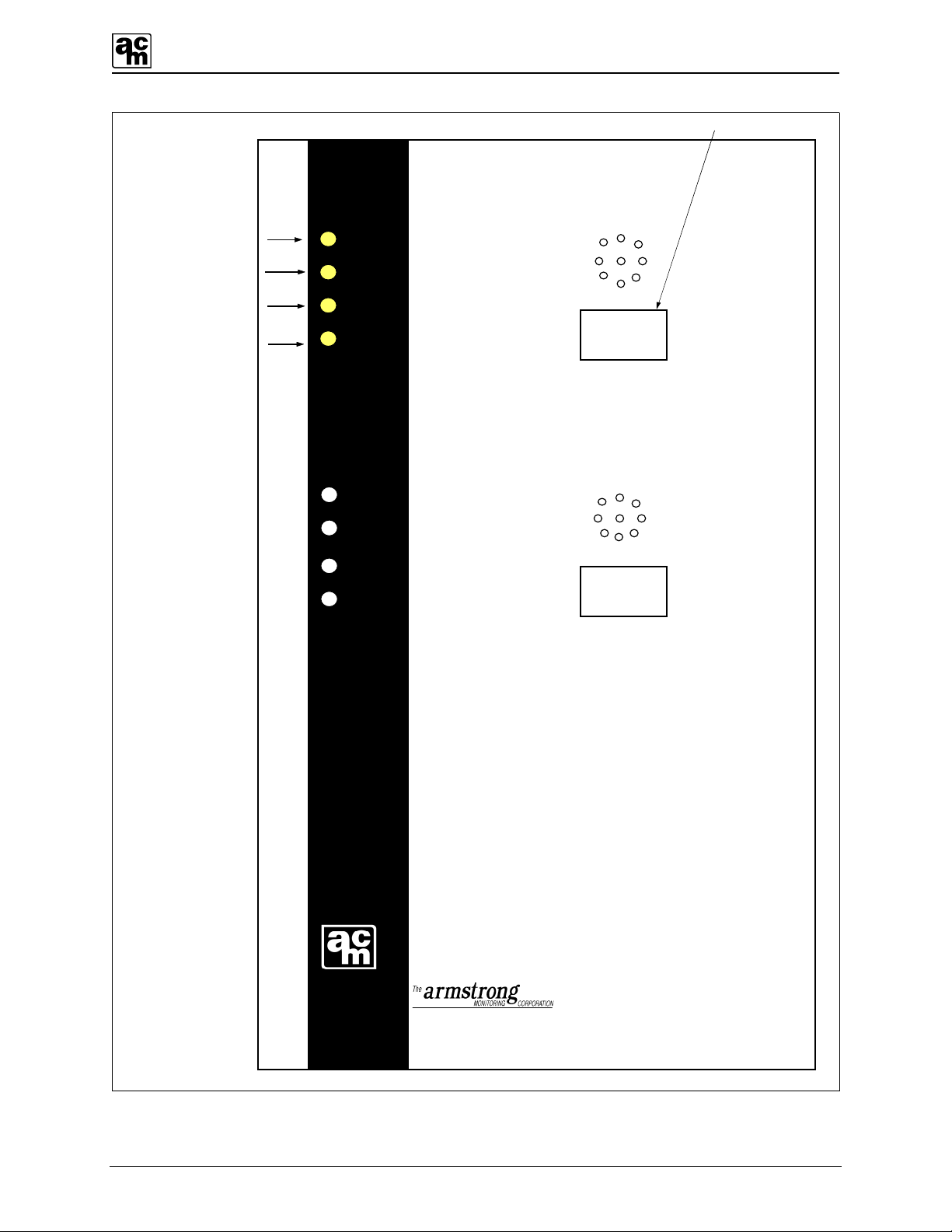
1. POWER ON INDICATOR: Power is indicated by a green LED.
2. FAIL INDICATOR: Sensor fail is indicated by an amber LED.
3. LOW ALARM INDICATOR: Low levels of gas are indicated by a yellow LED.
4. HIGH ALARM INDICATOR: High levels of gas are indicated by a red LED.
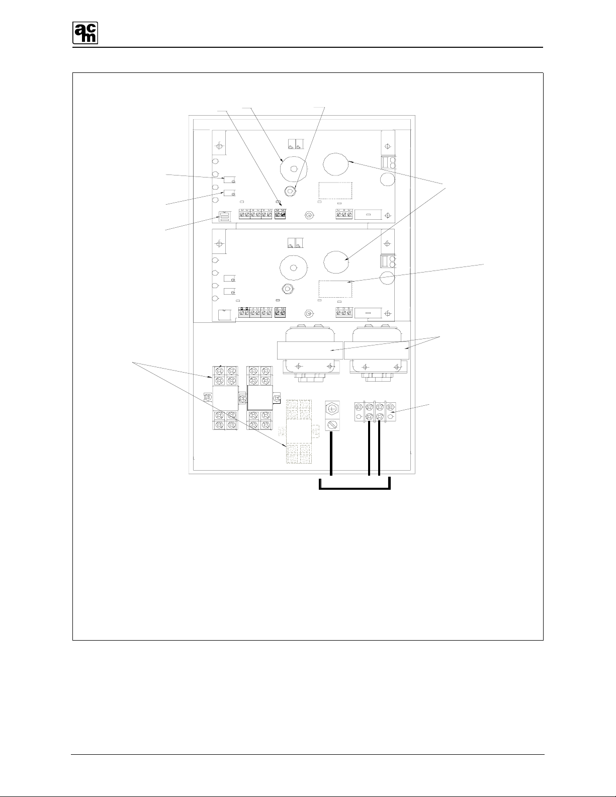
5. POWER TERMINAL BLOCK: For line voltage connections (120 VAC, 60 Hz.)
6. TEST SWITCH: The test switch is provided to electronically simulate alarms
in order to test the low and high alarm indicators and relays.
7. LOW ALARM ADJUST: Sets the Low alarm trip point.
8. HIGH ALARM ADJUST: Sets the High alarm trip point.
9. THREE CIRCUIT MINIATURE
SWITCH:
Each actuator on the miniature switch controls a different
circuit as shown in Figure 1.
9. a) TOP ACTUATOR: Provides a TEN-minute time delay, when the switch is ON,
to eliminate unnecessary alarms caused by momentary
exposure to high alarm conditions.
9. b) MIDDLE ACTUATOR: Provides a FIVE-minute time delay, when the switch is ON,
to eliminate unnecessary alarms caused by momentary
exposure to low alarm conditions.
9. c) BOTTOM ACTUATOR: Controls the audio alarm indicator. When ON, the buzzer
will activate when a high alarm condition occurs.
10. RELAYS:
There are up to 3 DPDT relays per monitor, which can work
with high alarm, low alarm, and fail.
11. TRANSFORMER:
Class II, step down transformer runs the internal circuitry at
low voltages.
12. AUDIO ALARM: When enabled, the buzzer will activate when a high alarm
condition occurs.
13. ANALOG OUTPUT: 4-20 mA output 250 ohms load maximum.
14. ON-BOARD SENSOR Allows local detection of gas.
15. OPTIONAL DC INPUT: Used for battery backup or a 12 VDC supply.

AMC-1040 CO / NO2 Vehicle Exhaust
5
HI
LOW
TIME DELAYS
ON
THREE POSITION
MINIATURE SWITCH
AUDIO ALARM
ACTUATORS
Figure 1: Three-circuit miniature switch.

AMC-1040 CO / NO2 Vehicle Exhaust
6
1
) Power On Indicator
2
) Fail Indicator
3
) Low Alarm Indicator
4
) High Alarm Indicator
1040
215 Colonnade Road South Nepean, Ontario, K2E 7K3
U.S. & Canada toll free 1 (800) 465
-
5777
POWER
FAIL
LOW
HIGH
POWER
FAIL
LOW
HIGH
1
2
Optional Display
095
03.2
PPM CO
PPM NO2
Figure 2: AMC-1040 monitor, front panel.

AMC-1040 CO / NO2 Vehicle Exhaust
7
4 INSTALLATION
4.1 LOCATION AND MOUNTING
Care should be taken to securely fasten the AMC-1040 monitor unit (using four mounting holes
provided) to a solid, vertical, non-vibrating surface or structure. (See Figure 4 for mounting
dimensions.)
Note:
All cable entry MUST be through the BOTTOM of the monitor enclosure only. Other
entry locations will allow foreign materials to enter the enclosure, possibly causing
damage to internal components. Mounting hardware and conduit connections are NOT
supplied.
4.2 WIRING OF THE MONITOR
POWER SUPPLY: The monitor operates on 120 VAC, 60 Hz. Class II step down
transformers run the internal circuitry at low voltages. The power
supply connections are made at the power terminal block located inside
the monitor. (See Figure 3)
RELAYS: Up to 3 DPDT relays are optionally available which activate with high
alarm, low alarm and fail respectively causing contact transfer. The
contacts are available for activating a remote alarm and/or, blower
motors where moving parts are fully guarded, pumps or lighting circuits.
Relays are rated 1/3 hp @ 120 VAC/240 VAC, 10 Amps @ 28
VDC/120 VAC/240 VAC resistive. For relay contact arrangement see
Figure 5. The high and low alarms relay coils are normally de-energized
and the fail relay coil is normally energized.
ANALOG OUTPUT: The AMC 1040 comes standard with a 4-20 mA output per channel.
This output corresponds to the gas range indicated on page 3. It can be
used for connecting to an external recorder or other device. The
maximum load is 250 ohms.

AMC-1040 CO / NO2 Vehicle Exhaust
8
11.
5.
8.
7.
13.
LOW
12.
12. AUDIO ALARM
COM.N.C.N.O.
COM.
N.C.N.O.
HOT
GND
CLASS-2 TRANSFORMERCLASS-2 TRANSFORMER
BUZZER
HIGH
LOW
FAIL
POWER
AUD
DLY
L
H
EC
ZERO
EC
SPAN
DISPLAY
OPTIONAL
BUZZER
HIGH
LOW
FAIL
POWER
AUD
DLY
L
H
EC
ZERO
EC
SPAN
DISPLAY
OPTIONAL
COM.
N.C.
6.
CO
9.
HIGH
10.
120 VAC
GND AC AC
-OUT+
-FAIL+-LO+-HI+
NO2
5. POWER TERMINAL BLOCK
6. TEST SWITCH
7. LOW ALARM ADJUST
8. HIGH ALARM ADJUST
9. THREE CIRCUIT MINIATURE SWITCH
10. RELAYS
11. TRANSFORMER
L
GND AC AC
-FAIL+-LO+-HI+
(OPTIONAL)
-OUT+
14. SENSOR
14.
13. ANALOG OUTPUT
15.
15. OPTIONAL DISPLAY
NEUT.
N.O.
FAIL
Figure 3: AMC-1040 VC monitor, power connections.

AMC-1040 CO / NO2 Vehicle Exhaust
9
1.0 6.0 8.0 1.0 12.0 14.0 4.0
DIMENSIONS
IN INCHES
A
B
CD
E
FDEPTH
A
B
C
D
E
F
G
6.0
G
Figure 4: Monitor mounting dimensions.

AMC-1040 CO / NO2 Vehicle Exhaust
10
RELAY
SOCKET
COM.
COIL
N.C.
N.O.
N.O. N.C.
COIL
COM.
RELAY SOCKET
CONNECTIONS
RELAY DE-ENERGIZED
75
31
86
42
COIL COM.
N.O. N.C.
RELAY ENERGIZED
BBB
AAA
86
42
COIL COM.
N.O. N.C.
75
31
Figure 5: Relay contacts wiring diagram.

AMC-1040 CO / NO2 Vehicle Exhaust
11
5 OPERATION AND CALIBRATION
5.1 OPERATION
Note:
BEFORE turning on the main power to the monitor, MAKE SURE all connections are
properly made.
Once power has been turned on, the GREEN power LED will light. A one-minute time delay
eliminates false alarms from occurring during the sensor’s warm up period. After this time
delay, the unit becomes fully operational. If time delays are required or the audio alarm
indicator is not needed, the three-circuit miniature switch can be set accordingly. Refer to
Section 3, Item 9 and Figure 1.
If any gas surrounding the sensor exceeds the low alarm trip point setting, the YELLOW LED
and low alarm relay will be activated. If any gas exceeds the high alarm trip point setting, the
RED LED, high alarm relay and audio alarm will be activated. An open sensor circuit is indicated
by the amber fail LED.
5.2 CALIBRATION
As the calibration procedure may cause the monitoring equipment to give a false alarm,
appropriate precautions should be taken. Instructions on introducing the gas sample are
included with the calibration kit or available separately (depending on type of gas or application).
To observe immediate reaction during calibration, the low and high alarm time delays should be
disabled.
5.2.1 EQUIPMENT REQUIRED
• Digital multimeter (for non-display versions)
• Miniature screwdriver
• Calibration gas (es)
• Calibration kit
5.2.2 ADJUSTMENTS
For full recalibration adjustments, follow the Set-Up Procedure steps 1 to 8 inclusive. There are
two adjustments to be made for periodic recalibration: Zero and Span adjustments and the
Alarm adjustments. Alarm adjustments are only required if the user wants to change alarms.
Refer to Figure 6 to perform the following procedure
1) Remove cover from monitor enclosure.
2) Plug in standard test leads fully into jacks on multimeter.
3) Switch ON multimeter and select the DC Volts range greater that 1.00 VDC.

AMC-1040 CO / NO2 Vehicle Exhaust
12
4) Insert Test Probe Tips into test points of PCB in the Upper Left area (see Figure 6.)
5) Insert the BLACK probe into the “COM TP” test point and the positive RED probe
into the “SIG TP” test point.
6) Apply a Zero gas sample, or with the sensor in clean air, adjust the Zero trimmer for
a stabilized reading of 0.00 VDC measured at the test points.
7) Apply a Span gas sample. The Span gas sample need not be of the full-scale
concentration but may be a fraction of this. Since the monitor output range is 0 to 1
VDC, a full-scale concentration gas should read 1.00 VDC after a few moments of
sensor exposure. Similarly, a half scale concentration gas should read 0.50 VDC.
8) Note: If required, calibration kits are available from AMC.
5.2.3 DIGITAL DISPLAY ADJUSTMENTS
For monitors equipped with a Digital Display calibration should be performed with the integral
display instead of a digital multimeter.
1. Apply a zero gas sample, or with sensor in clean air, adjust the Zero trimmer for a
stable reading of “0” on the display.
2. Apply a Span gas sample of the full scale or a fraction of full scale concentration and
adjust Span trimmer to the corresponding output on the display.
5.2.4 ALARM ADJUSTMENTS
Alarms are set at the factory and do not need to be adjusted unless a change in alarms is
required.
Low alarm adjust is used to establish the low alarm trip point. This is done by adjusting the
voltage to the appropriate fraction of full scale at test points COM and LOW TP (see Figure 7).
Example: Full scale = 100 ppm
Low alarm trip = 35 ppm
35/100 x 1 VDC
= 0.35 VDC
High alarm adjustment is done in the same manner as above, using the high alarm adjust and
measuring between COM and HIGH TP.

AMC-1040 CO / NO2 Vehicle Exhaust
13
6 PREVENTIVE MAINTENANCE
6.1 GENERAL
The monitor should be wiped clean with a damp cloth following a regular maintenance program.
Avoid spraying, submersion and other conditions that could cause a liquid to enter the monitor
and cause possible intrinsic damage to internal components.
6.2 VERIFICATION OF MONITOR
A test should be performed to ensure that no transmitter failures are indicated and that output
relays and auxiliary alarms are functioning properly. This test should be performed every 2
months, but for more demanding applications, verification should be performed on a weekly
basis.
6.3 SENSOR REPLACEMENT
The sensor should be replaced under the following conditions:
1. When the sensor element becomes an open circuit, the unit outputs a fixed 1 mA signal.
2. When the sensor no longer responds to the presence of gas or has an unstable “zero”
signal.
When the sensor needs replacing, reorder the “Sensor Part Number” listed in Product
Information, page 3. See Figure 6 for sensor replacement and wiring procedure.
Note:
Allow 24 hours for the new sensor element to stabilize (burn-in) before recalibration, then
follow instructions in the transmitter calibration section 5.2 of this manual.

AMC-1040 CO / NO2 Vehicle Exhaust
14
Figure 6: Calibration setup

AMC-1040 CO / NO2 Vehicle Exhaust
15
TB3
-IOUT+-FAIL+
TB3
BUZZER
TB6
TB2
11
HIGH LED
LOW LED
FAIL LED
POWER LED
AUD
DLY
L
H
-IOUT+
-LO+
-HI+
EC
ZERO
EC
SPAN
GND AC AC
FUSE
SENSOR
+-
MULTIMETER
DIGITAL
SIG
TP
COM
TP
LOW ALARM
ADJUST
HIGH ALARM
ADJUST
LOW
HI
TP
Figure 7: Alarm adjustments

AMC-1040 CO / NO2 Vehicle Exhaust
16
ON-BOARD SENSOR
STEP 1:
STEP 5:
STEP 4:
STEP 3:
STEP 2: REMOVE THE FOUR COVER SCREWS AND COVER PLATE FROM UNIT.
UNPLUG USED SENSOR ELEMENT FROM THE BOARD AND DISPOSE OF IT PROPERLY.
PLUG IN A NEW SENSOR ELEMENT ONTO THE BOARD, MAKING SURE SENSOR
PINS ARE ALIGNED WITH THE PIN SOCKETS.
CONNECT POWER AND RE-CALIBRATE.
REINSTALL COVER PLATE ONTO THE UNIT.
DISCONNECT POWER.
STEP 6:
LOW
COM.N.C.N.O.
COM.
N.C.N.O.
NEUT. HOT
GND
CLASS-2 TRANSFORMERCLASS-2 TRANSFORMER
TB5TB3
BUZZER
TB6
TB2
11
HIGH
LOW
FAIL
POWER
AUD
DLY
L
H
EC
ZERO
EC
SPAN
FUSE
DISPLAY
OPTIONAL
TB3 TB5
TB3
BUZZER
TB6
TB2
11
HIGH
LOW
FAIL
POWER
AUD
DLY
L
H
EC
ZERO
EC
SPAN
FUSE
DISPLAY
OPTIONAL
COM.
CO
HIGH
GND AC AC
-FAIL+
-LO+
-HI+
NO2
L
GND AC AC
(OPTIONAL)
-OUT+
N.C.N.O.
FAIL
-FAIL+
-LO+
-HI+
-OUT+
FIGURE 8: Sensor replacement.
Table of contents
Other AMC Microphone manuals