GIGAMEDIA GGM PAMICUHFG User manual

GGM PAMICUHFG USER
MANUAL
PUBLIC ADDRESS
www.gigamedia.net
UHF TRUE-DIVERSITY
WIRELESS MICROPHONES
Please follow the instructions in this manual to obtain the optimum results from this unit.
We also recommend that you keep this manual handy for future reference..

www.gigamedia.netGIGAMEDIA User manual 2
The below unit is a true diversity dual-channel receiver with factory preset user-selectable
200-frequency.
1. True-diversity dual receiver controls, features & indicators
View of front panels
View of back panels
Menu button: press "","" button to access or select menu screens selected, press the SET
button again to save.
SET button: one-touch SET button to sync quickly deploys them to transmitters by IR.
SCAN: press the SET button on receiver to access the scan function for the best available
channel.
Display: shows menu options, receiver and transmitter settings.
Volume control.
IR align window: align with the transmitter IR window during an IR sync to automatically
program transmitters.
Power switch: press and hold the power button to turn on receiver.
Power supply jack: connection point for DC of 12 V / 1 A power supply.
1
1
2
2
3
3
4
4
5
5
1
1
2
2
3
3
4
4
6
6
DC INPUT
ANT B
BAL A OUT
UNBAL OUT
BAL B OUT
B
12-15V 800mA
A+B
UNBAL A
ANT A
OUT
78 8
9
11
10 12
9

www.gigamedia.netGIGAMEDIA User manual 3
Antenna connectors : BNC connector for receiver antennas.
XLR audio output: balanced.
1/4 mix audio unbalanced output: channel A and B CH mixed when (11) switch slip to end of
A+B, unbalanced output jack for B channel only when (11) switch to of end B.
Switch of A and B CH unbalanced mixed or separate audio output.
Unbalanced output jack for channel A only.
Size (W x H x D): 420 x 44 x 180 mm
Be to be mounted in a standard audio equipment rack with factory offers mounting brackets.
1.1. Operation receiver
Make sure that the transmitter is powered off before turning the receiver power on. Press and
hold the receiver power button, the LCD will glow and turn on. Then press ""," " button to
choose function, or then press “SET’’ button to access the scan function for the best available
channel.
1.2. The LCD display
RF bar indicators: 8-bar indicates the strength of radio frequency signal.
AF bar indicators: 8-bar indicates the strength of audio signal.
When the LCD shows FREQU, it is the current working frequency.

www.gigamedia.netGIGAMEDIA User manual 4
When the LCD shows CHANNL: it is the current working channel.
6-segment: shows frequency, channel and menu.
Mute sign: shows that no RF signal is received.
1.2.1. Main menu
1.2.2. Scan frequency
1.2.3. Manual frequency
Press “SET“ button, the LCD below will present on display first:
The receiver scans the RF spectrum for the best available frequency press SET button to star the
scan.
When the scan is complete, the selected channel will appear on the display.
When press " "," " button. It shows 0-99 or 100-199 digits when choose CHANNL; it shows real
carrier frequency when you choose FREQU.
After 2-3 s, one of two pictures below will present: it depends on last status before turning the
system off. The CPU of receiver remembers last status LCD displays what stored last time when
the CPU was shut off.

www.gigamedia.netGIGAMEDIA User manual 5
After SET, press “SET” button to save, if not save, the receiver will return to last status. The LCD
will blink if no confirmation is made: this is to invite a confirmation.
(The LCD will display one of the above depends on last status).
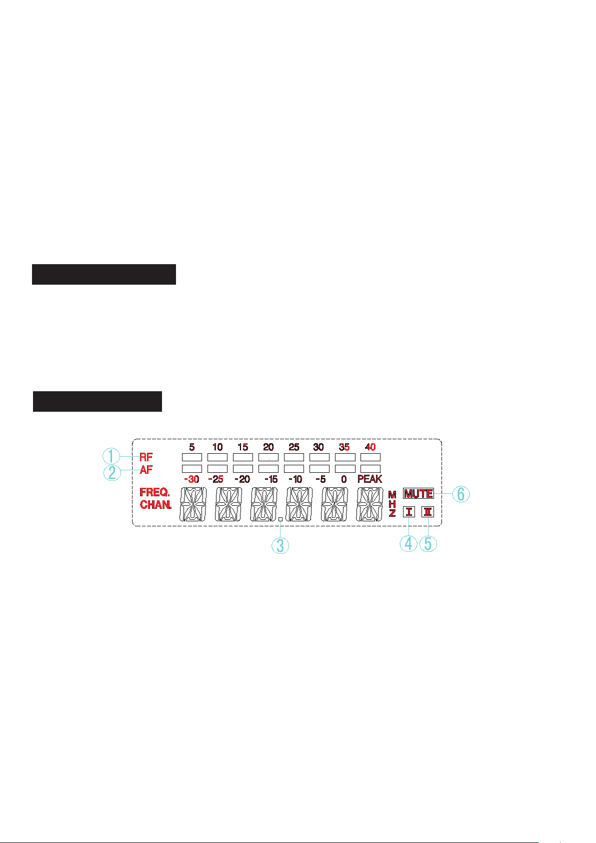
1.2.4. How to set MUTE of receiver
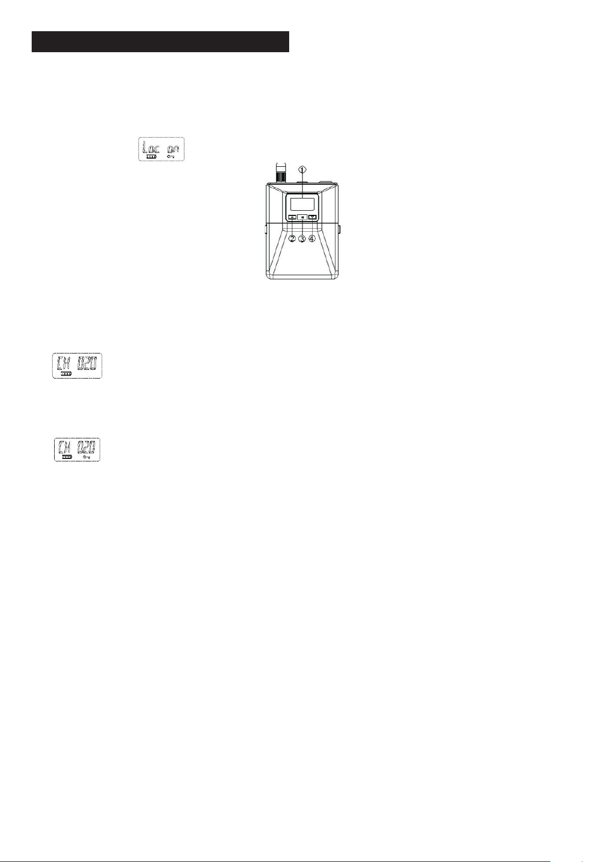
1.2.5. System lock operation
Press “SET’’ button to access SQELCH menu.
Press “SET” button and hold seconds, LCD wll dsplay squelch lke 15 dB ndcates senstvty
status Press " "," " button to change current status f need Ths pont s a factory pre-set
at 0-40 dB 5, 10, 15, 20, 25, 30, 35, 40 dB postons are to provde optmal operaton n most
applcatons Poston at 40 dB wll decrease operatng range
Control lock options is available for receiver to protect against accidental or unauthorized
operation.
Locks can be directly set from the menu as follows.
Press “SET” button for 2-3 s, LCD will appear on the display as follows:

www.gigamedia.netGIGAMEDIA User manual 6
After 2-3 s, LCD will change to one of the following diagrams.
It depends on the last status when LCD was turned off to see what it will show now.
If the LCD shows LOC ON, protect against accidental or unauthorized changes.
If it is in LOCK ON mode, press “SET” button and hold then press " "," " button to set to LOC OFF.
2. Handheld transmitter controls, features & indicators
Metal grille: hexagonal-shaped to protect the microphone cartridge from being damaged,
reducing breath sounds and wind noise.
LCD display: indicate channel and remaining battery life.
IR align window: align with the receiver IR window during an IR SYNC to automatically program
transmitters.
Microphone gain control: provide audio level adjustment to accommodate different sound
source.
RF power: setting LO or HI.
Lock ON/OFF switch.

www.gigamedia.netGIGAMEDIA User manual 7
Power switch button.
Handheld integrated antenna.
Charger port: using factory offers bay chargers and works Ni-MH AA rechargeable batteries
only.
Turn on the handheld transmitter.
Press the SET SYNC button on receiver. The IR LCD indicating the
sync mode is active.
Align the IR sync windows of the handheld transmitter and receiver
at a distance of less 20 cm. When the handheld transmitter and
receiver are aligned. The display of handheld transmitter will appear
channel no. as same as receiver when IR is complete.
If the IR SYNC fails, repeat IR SYNC procedure again.
2.1. IR SYNC for automatic handheld transmitter set up

www.gigamedia.netGIGAMEDIA User manual 8
3. Body-pack transmitter controls, features & indicators
LCD display: indicate channel and remaining battery life
Audio gain control "" and unlock button: increase audio gain and control unlock.
IR align window: align with the receiver IR window during an IR SYNC to automatically program.
transmitters.
Audio gain control ""and lock button: decrease audio gain and control lock.
Battery compartment: recommend Ni-MH AA batteries ×2 or AA x2 rechargeable batteries.
Belt.
Antenna.
Power button.
Audio balanced input jack.
Charger port: using factory offers bay chargers and works Ni-MH AA rechargeable batteries
only.

www.gigamedia.netGIGAMEDIA User manual 9
3.1. Lock audio gain level controller button
To control lock audio gain level options is available for body-pack transmitter to protect against
accidental or unauthorized changes during the performance the audio gain controller button
" "," " has been factory pre-set to provide satisfactory output grade 16-18 in most applications.
Display show as:
.
.
➀If adjust audio gain level controller necessarily. Press (the button ) for while the LCD will
appear on the display as:
to control unlocked.
➁ After adjusting audio gain level to suitable as you want, press the (button ) for while to
control lock again as display show as:

www.gigamedia.netGIGAMEDIA User manual 10
4. Charger user’ manual
4.1. Features
A new generation of charger designed exclusively for rechargeable transmitters of body-pack
transmitter and handheld transmitter conveniently.
Each charger has two charging slots.
Each slot has a 2-in-1 charging design, enabling multiple charging options:
• Two handheld transmitters.
• Two body-pack transmitters.
• One handheld & one body-pack transmitter.
• Each charger share a LCD to provides precise dynamic charging battery status indicators for
easy reading by the users.
• Intelligent charging circuitry provides efficient and safe charging.
• The structural design of slots to avoid charge polarity error.
• Two or more chargers can be easily connected for more charging options by charging cable.
Wrong battery charging alarm indicators: using bad quality battery or non-rechargeable battery,
the LCD indicate alarm sign.

www.gigamedia.netGIGAMEDIA User manual 11
4.2. Controls and indicators:
4.3. Power jack
Rear charging slot: for handheld transmitter (for body-pack transmitter available).
Front charging slot: for body-pack transmitter (for handheld transmitter available).
➂LCD display:
Power IN: from adaptor.
Power OUT: to next charger by charging cable.

www.gigamedia.netGIGAMEDIA User manual 12
4.4. Display
Charge current: 0.5 A for two transmitters charging at the same time
Charge time: 50 % about 1 h; 90 % about 3 h
External power supply: 12 V / 1 A for one charger or more power supply be required when more
chargers to be connected for charging at same time
Dimensions (W x H x D ): 70 x 98 x 165 mm
Weight: 365 g
Display for rear charging slot.
Indicates front and rear slots.
Display for front charging slot.
4.5. Specifications

www.gigamedia.netGIGAMEDIA User manual 13
5. Specifications of system
• Frequency range: UHF range 470-510 MHz, 640-690 MHz, 863-865 MHz, 823-832 MHz
•Modulation mode: PLL
• Bandwidth: 25 MHz
•Channel: 200 channel interval 25 KHz
•Stability: ± 0.0005 %
•Dynamic range: 100 dB
• Max deviation: ± 80 KHz
• Frequency response: 20 Hz-20 KHz ± 3 dB
• S/N: > 85 dB
• Distortion: < 0.5 %
•Operation temperature : -10 °C ~ 60 °C
• T.H.D: < 0.5 % (at 10 KHz deviation)
•Power supply: DC 12 V~500 MA
• Audio output: balanced & unbalanced
• LCD displays: frequency, RF input level, AF level, muting RF level and wireless channel
information
6. Specifications of the receiver
•True-diversity receiving mode: PLL synthesized oscillation mode
• Inter frequency:
first: 110 MHz /
second: 10.7 MHz
• Antenna type: BNC type / 50 Ω
•Sensitivity: 12 dBµV (80 dB S/N)
• Sensitivity range: 12-32 dBµV
• Spurious emission: ≥ 75 dB
•Max audio output: +10 dBV
7. Specifications of the transmitter
•RF output:
HI: 30 mW
LO: 10 mW (meet CE / FCC regular)
•Spurious emission: -60 dB
• Operation battery: AA x 2
• LCD displays: channel and battery status
Directive DEEE
Directive CE
This product is covered by the WEEE II Directive (Directive 2012/19 / EU). It should not be thrown in the trash or
dumped. Substances in the product may be hazardous to human health or the environment. Disposal may be done by
returning the product to your dealer or leaving it a collection point provided for this purpose.
This product bears the CE mark which certifies its conformity with the directives LVD 2014/35/EU ; EMC 2014/30/EU
and RoHS 2011/65/EU.
Compliance has been assessed in accordance with applicable standards in effect.
Other GIGAMEDIA Microphone manuals