Shure Incorporated
10/37
•
•
•
◦
◦
◦
◦
•
•
•
•
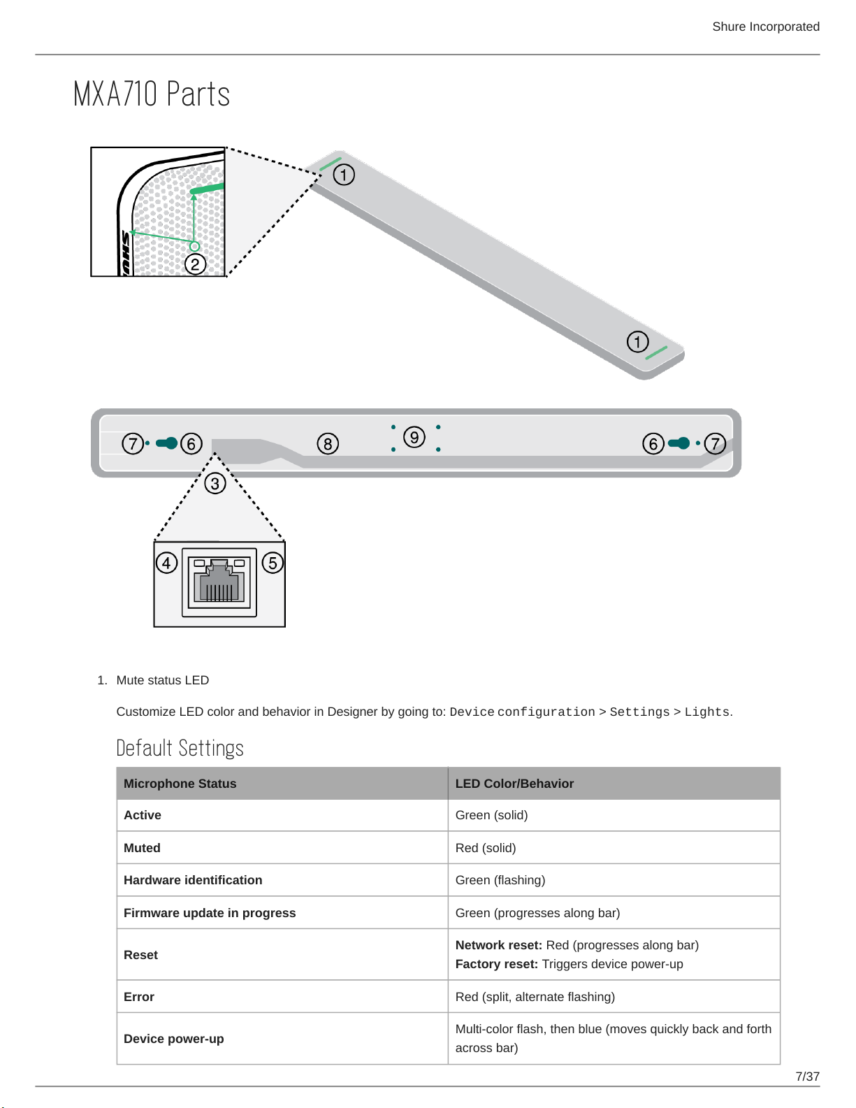
Reset Modes
Network reset (press for 4-8 seconds): Resets all Shure control and audio network IP settings to factory defaults.
Full factory reset (press for more than 8 seconds): Resets all network and configuration settings to the factory defaults.
Installation Guide
Choosing Where to Install the MXA710
The MXA710 is an extremely versatile microphone. You can install it in many places in a conference room and easily get good
coverage for all talkers.
MXA710-2FT MXA710-4FT
Room size Small to medium Medium to large
Maximum number of lobes 4 8
Recommended distance from talkers 2 to 16 feet 4 to 20 feet
Best Practices for Installation
Before installing, open the microphone's coverage map in Designer. Look at the 4 device installation templates to under
stand how the lobes behave when you move them around and use different widths. Lobes also have Autofocus technolo
gy, which fine-tunes each lobe position in real time, even if meeting participants lean back or stand up. Templates are
available for:
Wall horizontal
Wall vertical
Ceiling
Table
Measure your space and make sure that all talkers will fit in the microphone's coverage area.
Coverage also depends on your room's acoustics, construction, and materials. Take these into consideration when plan
ning coverage.
Don't place the microphone behind obstructions. Keep the microphone's grille at least 36 inches away from any occupan
cy sensors.
Plan for any future coverage needs.
Ways to Install the MXA710
Accessory Install location Other hardware required?
Wall-mounting bracket Wall Drywall mounting screws and anchors
Display mount kit Attach to display mount
Peerless Universal Sound Bar Kit,
Chief Thinstall Center Channel Speaker
Adapter, or other similar adapter with
VESA MIS-B compatibility
Suspended Cable Ceiling
Braided metal cable
Hardware to attach cable to ceiling or
A710-TB Tile Bridge