Amcrest AC-2 User manual

Model: AC-2
Need more help?
amcrest.com/support
Get the most out of your Amcrest
product. Check out our FAQs,
instructional videos and support
page.
facebook.com/amcrest
twitter.com/amcrestsecurity
© 2018 Amcrest Industries. All rights reserved.
1.888.212.7538
Amcrest Care
Video Baby
Monitor
Generation 2
User Manual
www.facebook.com/amcrest
www.twitter.com/amcrestsecurity
www.amcrest.com/support

If your experience has been something
less than amazing, please give us a ring at
1-888-212-7538
FCC Statement, Welcome ......................... 3
Important Safeguards & Warnings ......... 5
Quick Start Guide ...................................... 7
1 User Manual ....................................... 11
1.1 Features .................................................................. 11
1.2 Specification Chart .............................................. 12
1.3 Package Contents ................................................ 14
2 HandsetOverview .............................. 15
2.1 Physical Handset Overview ............................. 15
2.2 Display On/OFF .................................................... 15
2.3 Push To Talk ........................................................... 15
2.4 Menu .......................................................................... 16
2.5 Tilt Up ................................................................. 16
2.6 Tilt Down ................................................................. 16
2.7 Pan Right ................................................................. 16
2.8 Pan Left .................................................................... 16
2.9 Function (Fn) ......................................................... 16
2.10 Power On/OFF ...................................................... 16
2.11 OK ............................................................................... 16
2.12 Volume Up ............................................................... 17
2.13 Volume Down ......................................................... 17
2.14 Zoom In/Out ........................................................... 17
2.15 Switch Camera ....................................................... 17
2.16 Power Indicator ......................................................17
2.17 Link Indicator .......................................................... 17
2.18 Battery Cover Lock ...............................................18
2.19 DC Power Adapter Input .................................... 18
2.20 Antenna .................................................................... 19
2.21 Speaker ..................................................................... 19
2.22 Clip ............................................................................. 19
2.23 Handset Cutout ..................................................... 19
2.24 Battery Comparment .......................................... 19
2.25 Handset Stand (Hanging Position) ................ 20
2.26 Handset Button Menu ......................................... 20
2.27 Handset Primary Buttons .................................. 20
2.28 Alternate Functions ............................................. 21
2.29 Menu Icon Overview ............................................ 21
3 Camera Overview .................................... 22
3.0 Physical Handset Overview .............................. 22
3.1 Optic Lens ............................................................... 22
3.2 IR LED Array .......................................................... 22
3.3 Ambient Light Sensor ......................................... 22
3.4 Nightlight ................................................................. 22
3.5 Speaker ..................................................................... 23
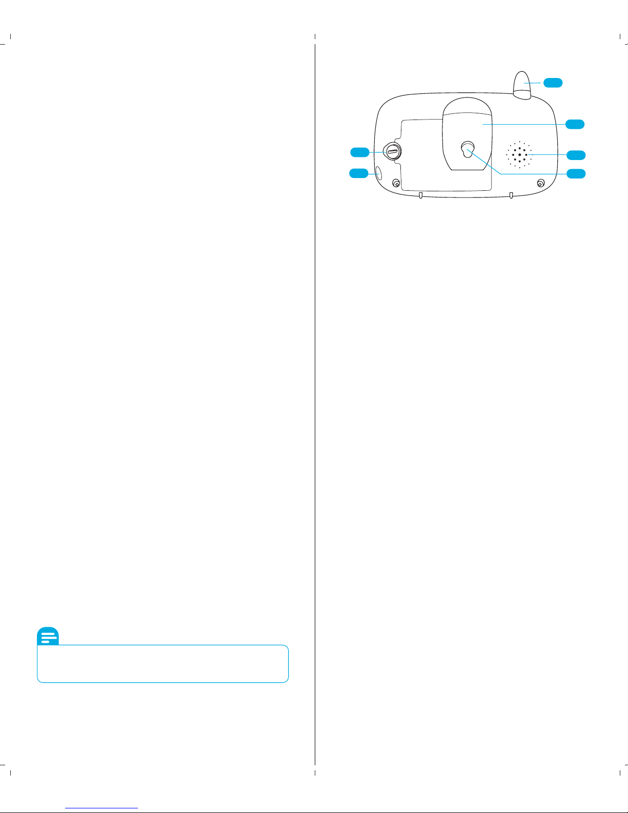
3.6 Antenna .................................................................... 23
3.7 Thermometer Probe ............................................ 23
3.8 On/O Switch ........................................................ 23
3.9 Power Adapter Input ........................................... 23
3.10 Service Port ............................................................. 24
3.11 Pairing Button ........................................................ 24
3.12 Wall Mount .............................................................. 24
4 Camera Overview ............................. 25
4.1 Powering the Camera Unit ................................ 25
4.2 Insttallation of Handset Battery ...................... 25
4.3 Charging ................................................................... 26
4.4 Pairing Your Handset & Camera ..................... 26
4.5 Wall Mounting The Camera Unit ..................... 27
4.6 Charging ................................................................... 28
5 Usign The Amcrest Care Monitor ... 29
5.1 Setting Up Your Camera .................................... 29
5.2 Alternate Functions ............................................. 29
5.3 Pan & Tilt .................................................................. 29
5.4 Night Vision ............................................................ 29
5.5 Talk Mode ................................................................ 30
5.6 Sellep Mode ............................................................ 30
5.7 Screen Timer and VOX ....................................... 30
5.8 Colume control ...................................................... 31
5.9 Screen Brightness ................................................. 32
5.10 Digital Zoom ........................................................... 32
5.11 Adding & Removing Cameras .......................... 32
5.12 View Dierent Cemeras ..................................... 33
5.13 Lullaby ....................................................................... 33
5.14 Nightlight ................................................................. 34
5.15 Terperature Display ............................................. 34
FAQs/Troubleshooting ............................ 35
Table of contents

For access to the quick start guide and other
support information, go to
www.amcrest.com/babycam
To contact Amcrest support, please do one of the
following:
Visit www.amcrest.com/contacts and use the email
form Call Amcrest Support using one of the follow-
ing numbers
Toll Free: (888) 212-7538
International Callers (Outside of US):
+1-713-893-8956
USA: (888) 212-7538
Canada: 437-888-0177
UK: 203-769-2757
Email Amcrest Customer Support
Welcome to the
Amcrest Family!
Thank you for purchasing our Amcrest
Care! This user manual is designed to be
a reference for the installation and
operation of your camera. Here you can
find information about the camera's
features and functions, as well as infor-
mation to aid in troubleshooting. It is
important to read this user manual
carefully and in its entirety as it contains
detailed information needed to properly
use your Amcrest Care. If you have any
issues setting up or using your Amcrest
baby monitor, please call our Customer
Support.
FCC
Statement
1- This device complies with Part 15 of the FCC Rules.
Operation is subject to the following two conditions: (1) this
device may not cause harmful interference, and (2) this
device must accept any interference received, including
interference that may cause undesired operation.
2-The users manual or instruction manual for an intentional
or unintentional radiator shall caution the user that changes
or modifications not expressly approved by the party
responsible for compliance could void the user's authority
to operate the equipment. In cases where the manual is
provided only in a form other than paper, such as on a
computer disk or over the Internet, the information
required by this section may be included in the manual in
that alternative form, provided the user can reasonably be
expected to have the capability to access information in
that form.
3- (b) For a Class B digital device or peripheral, the instruc-
tions furnished the user shall include the following or similar
statement, placed in a prominent location in the text of the
manual: NOTE: This equipment has been tested and found
to comply with the limits for a Class B digital device, pursu-
ant to Part 15 of the FCC Rules. These limits are designed to
provide reasonable protection against harmful interference
in a residential installation. This equipment generates, uses
and can radiate radio frequency energy and, if not installed
and used in accordance with the instructions, may cause
harmful interference to radio communications. However,
there is no guarantee that interference will not occur in a
particular installation. If this equipment does cause harmful
interference to radio or television reception, which can be
determined by turning the equipment o and on, the user
is encouraged to try to correct the interference by one or
more of the following measures:
›Reorient or relocate the receiving antenna.
›Increase the separation between the equip
ment and receiver.
›Connect the equipment into an outlet on a
circuit dierent from that to which the receiver
is connected.
›Consult the dealer or an experienced radio/TV
technician for help.
RF exposure warning: This equipment must be installed
and operated in accordance with provided instructions and
the antenna(s) used for this transmitter must be installed to
provide a separation distance of at least 20 cm from all
persons and must not be co-located or operating in
conjunction with any other antenna or transmitter. End-us-
ers and installers must be provide with antenna installation
instructions and transmitter operating conditions for
satisfying RF exposure compliance.
43

Important
Safeguards &
Warnings
1. Electrical Safety
All installation and operation should conform to your
local electrical safety codes. The product must be
grounded to reduce the risk of electric shock. We
assume no liability or responsibility for any fires or
electrical shock caused by improper handling or
installation.
2. Transportation Security
Heavy stress, violent vibrations, and excess moisture
should not occur during transportation, storage, and
installation of the device.
3. Repair Professionals
All examination and repair work should be done by
qualified service engineers. We are not liable for any
problems caused by unauthorized modifications or
user-attempted repair.
4. Environment
This device should be installed and kept in a cool, dry
place away from direct sunlight, flammable materials,
explosive substances, etc. This product should be
transported, stored, and used only in the specified
environments as stated above.
5. Accessories
Be sure to use only the accessories recommended
by the manufacturer. Before installation, please open
the package and check to ensure that all of the
components are present. Contact the retailer that
you purchased from or Amcrest directly if anything
is broken or missing in the package.
Important Safety
Information
This product is designed to be an aid and should
not be used to substitute responsible and proper
adult supervision.
This product is designed to provide sound and video
transmission for those times when a responsible
adult is not in the same room as the baby in care.
This baby monitor is not a medical device, nor a
device to prevent cases of Sudden Infant Death
Syndrome (SIDS). Do not solely rely on it for a baby's
wellbeing. It is important to regularly check on the
baby in care in person.
Make sure the camera, handset, and power adaptor
cables are kept out of reach, at least one yard away,
from your baby and other young children at all times.
Never place the camera unit or handset unit inside
your baby's bed or playpen. Ensure that all device
components are well out of the reach of your child at
all times. Never cover the handset or baby unit with
clothing, towels or blankets, or any other item.
Ensure that all components associated with this
device are not subject to moisture or liquid (e.g. near
bath or pool). Immersing in water could cause
electric shock and even death. Upon installation,
maintain a distance of at least one yard from other
electronic equipment, such as microwave ovens or
Wi-Fi routers, otherwise, Electromagnetic frequency
interference may be experienced. During continual
use, the baby unit power adaptors may become
warm to the touch. This is normal and should not be
a concern.
Battery Safety
Batteries may represent a hazard to your health and
the environment.
Do not dispose of batteries in a fire as they may
explode. Dispose of batteries according to local
regulations, never in your household rubbish as they
contain toxic, ecologically hazardous heavy metals.
› Do not open, bend, puncture, or shred batteries.
If a battery leaks, do not let the battery liquid touch
skin or eyes. If this happens, immediately flush the
aected areas with water, and seek medical
assistance.
› Do not modify or attempt to insert foreign
objects into the battery or expose it to any liquids.
Batteries may explode or leak if damaged.
› Use only the battery supplied with the product.
Use of unapproved batteries may present a risk of
fire, explosion, or other hazards, and will nullify the
device warranty.
65

Quick
Start Guide
Connection & Installation
This section provides information about
pairing the handset with the camera.
Once powered on, a battery icon with a lightning bolt
will display on the upper right-hand of the screen. This
indicates the handset is charging. When the handset is
completely charged, the battery indicator shown on
the screen will be full and you may disconnect it from
the charging cable as desired.
Powering on the Camera
❶
Connect the included power
adapter to a wall outlet.
❷Connect the camera to the
power adapter.
❸Slide the ON/OFF switch to
the ON position.
Powering on the Handset
❶
Connect the included
power adapter to a wall outlet.
❷Connect the handset to
the power adapter.
❸Press and hold the power
button until the handset
powers on.
On/O
Press and Hold to Speak
Configuration Settings
Tilt Camera Up
Tilt Camera Down
Pan Camera Right
Pan Camera Left
Indicates if the device is
powered on or o.
Indicates the status of the
connected cameras. When lit
indicates there is no link.
Display
Push to Talk
Menu
Tilt Up
Tilt Down
Pan Right
Pan Left
Power
Link
Icon Description Options
Handset Button Menu
Pairing your Handset & Camera
By default, the camera and the handset comes paired
and should be ready to use, However, If for any
reason pairing needs to be reestablished between the
handset and the camera, please Follow these
instructions:
❶
Within the handset menu please navigate to the
setting icon
❷Next, navigate to "Add" and press the button
located between the standby and buttons
on the handset face.
❸Now, select a channel and press to start the
pairing process.
❹Located under the camera, press and hold the
button while the camera is powered on. If the pairing
process was completed within the allotted time, you
should see an image captured by the camera unit.
Please note that the handset will only pair
within 15 seconds. If the camera does not pair
within this time you will need to begin the
process again.
!
87

5 Levels
5 Levels
On/OFF
5 Lullabies, All
1 Min, 3 Min, 4 Min
Del, Add, View, Scan
Adjust Voice Detection
Sensitivity
1-36 °C / 34-97 °F
Volume
Screen
Brightness
Night Light
Lullaby Music
Sleep Mode Delay
Camera Options
VOX
Voice Detection
Sensitivity
Current Camera
Unit Temperature
Icon Description Options
Menu Icons Overview
On/O
Confirm Selections
Activate Alternative
Function
Turn Volume Up
Turn Volume Down
Enable/Disable
Scan Between Cameras
Feeds
Power
OK
Alternative
Function
Volume Up
Volume Down
Zoom
Camera Scan
Icon Description Options
Alternative Function (Fn) Icons
Device does not turn on:
› Confirm the camera and monitor unit are both ON (check
Power LED indicator).
› Check that both handset and camera units are charged or
plugged into a charger.
› Battery may be depleted and may need to be recharged or
replaced.
› Check that power adapters are connected correctly.
"Out of Range" displaying on handset unit:
› Move the handset closer to the camera unit.
› Register the camera to the handset unit.
› Reset both units by disconnecting them from battery and
electrical power. Wait about 15 seconds then reconnect and pair.
› Large metallic objects including mirrors, doors, refrigerators,
fillings cabinets, may also block radio signal if it is between the
two units.
› Signal strength may be reduced when in close proximity to
radio or other electrical equipment such as TVs, computers,
phones, fluorescent light, or dimmer switches.
› Use of 2.4Hz product such as WiFi routers, Bluetooth
systems, or microwave ovens may cause interference. Keep
camera and handset units at least 5ft from these items or turn
them o.
Reception Interference:
› The camera and handset units may be too far apart. Move
the handset unit closer to the camera unit.
› The battery power may be too low.
› Check for interference from other electronic devices.
› Handset and camera unit may be too close in proximity to
large metallic objects causing interference.
› Use of 2.4Hz product such as WiFi routers, Bluetooth
systems, or microwave ovens may cause interference. Keep
camera and handset units at least 5ft from these items or turn
them o.
High pitched noise from handset unit:
› Increase the distance between the handset and camera unit.
› Volume may be too high. Reduce the volume on the handset
unit.
› Camera unit may be too far from the handset unit. Move the
camera unit closer to the handset unit.
› Make sure camera and handset units are placed away from
other electrical equipment, such as television, computer, or
phone.
Troubleshooting
For access to the quick start guide and other
support information, go to
www.Amcrest.com/babycam
109

The Amcrest Care system is an excellent product
that can be useful to a wide variety of users that
have babies or small children to monitor. Once
paired, the camera connects to the handset for in
home real-time viewing to provide an added sense
of security for your child's wellbeing.
User Manual
1
Amcrest Care system has the following features:
Pan, Tilt, and Zoom
Camera panning, tilting, and zooming are all features
available that allow peace of mind by knowing that
your child is safe. Pan into an area, tilt up, down, side to
side, and zoom in for a closer look.
Real Time Viewing
See what's going on right now and view your child in
real-time. No delay or lag, just pick up the handset and
watch your child whenever you need.
Two-Way Communication
Always hear your child through the handset via the
camera. The Amcrest Care comes with the added
benefit of two-way communication. Speak through the
handset to the location of the camera. This is especially
helpful when calming a baby or speaking to a caretaker.
VOX
See and hear your child through your handset as soon
as they make a noise or any other sound detected by
VOX. This useful feature allows the user to set the
appropriate ambient sound in the room. The monitor
will wake up and display an image of what is happening
when sound in detected in the camera viewing area.
Lullaby
Whether it's time for a nap or time for bed, we have
incorporated lullabies to help soothe your baby to
sleep. Pick from five classic lullabies or play all of them,
one after another.
Night Vision
The Amcrest Care system includes night vision that will
automatically illuminate a dark room without extra
steps. This feature is non-visible to the naked eye and
allows you to view your child without disturbing them.
1.1 Features
1.2 Specification Chart
LCD Type
LCD Backlight
Display Language
Time / Date in Idle
Display
Parent Unit Indicator
LED Indicators
Battery Indication
Battery Low Warning
Indicator
Out of Range Indication
Baby Unit Sound Level
Indication
Baby Unit Sound Level
Alert
General Features
Communication Type
Remote Control Baby
Unit
Belt-Clip
Antenna Type
Zoom In
Microphone
Microphone Sensitivity
(VOX)
Speakerphone Volume
Level
Temperature Alert
Temperature Display
DC Jack
Power Adaptor
3.5" Color TFT 320 x 240
Yes
On / O is English, others by icons
No
Change power / battery low / charge =
Green Color Unlink / Out of Range = Red
Color Voice Level = 3pcs green color and
2pcs red color
Display on LCD
3 levels + empty in LCD icon
Yes, Unlink LED flash
5 LEDs (3 green + 2 red)
No
2-Way
Yes (night light on/o; Lullabies selections,
Lullabies, Play/Stop and Pan / Tilt)
Yes (Non-Detachable)
External Fixed
Yes, 2X (Can Pan/Tilt by long press menu
key)
Yes, as push to talk
6 levels (O, 1, 2, 3, 4, 5) Default: 3
Visual Indicator
(Degree C / F selection)
Yes (Unit works with or without battery inserted)
Switching Mode Adaptor: 5.9V 1A
Display
1211

Key
CMOS Sensor
Imaging Device
Lens Focal Length
Angular Field of View
(Horizontal)
Max Aperture Ratio
Night Vision
Antenna
Temperature Sensor
Light Sensor
Wall Mount Holes
Indicators
Power indicator
Microphone
Speaker
Pan Angle (Horizontal)
Tilt Angle (Vertical)
Night Light
Lullabies
Backup Battery Type
DC Jack
Power Adaptor
Power On / O Slide Key Pairing Key
VGA, 640 x 480 pixels
5/1" CMOS
F2.8mm
Degree 50
F2.8
8pcs IR LED - 940nm
External
Yes
Yes
Yes
Power LED
Yes
Yes
Yes
300°
110°
Menu Selectable On / Of Default: On
Yes, 5 songs
No
Yes
Switching Mode Adaptor : 5.9V 1A
Baby Camera
1 x Camera Unit
.................................................................................................
1 x Parent Handset
.................................................................................................
1 x Battery
.................................................................................................
2 x Power Adapter
.................................................................................................
1 x Screw and
Wall Fishers
.................................................................................................
1 x User Manual
& Reference Card
.................................................................................................
1.3 Package Contents
AC-2
Wireless Pan/Tilt Baby Camera
with 3.5” Color Monitor
For access to the quick start guide and other
support information, go to
www.amcrest.com/babycam
1413

Handset
Overview
2.2 Display On/O
This button serves two functions: to power the device
on and o, and to turn o the screen. Press and hold
the button to power on the device. Inversely, press and
hold this button to power o the handset. To only turn
o the screen while the handset is on, quickly press this
button. This will allow the screen to turn on when the
VOX sound sensitivity threshold is met if this function is
active (see section 5.6 for more details).
2.3 Push To Talk
Press and hold the talk button to activate the micro-
phone on the handset. This function will engage the
user's voice and transmit it through to the speaker on
the camera.
In this section we cover the features and functionality
of your Amcrest Care handset.
2.2 Display On/O 2.3 Push to Talk
2.4 Menu 2.5 Power On/O
2.6 OK 2.7 Function
2.8 Volume Up 2.9 Volume Down
2.10 Zoom In/Out 2.11 Switch Camera
2.12 Movement/Pan Up 2.13 Movement/Pan Down
2.14 Movement/Pan Right 2.15 Movement/Pan Left
2.16 Power Indıcator 2.17 Link Indıcator
2.1 Physical Handset Overview
2.2
2.3
2.4
2.17
2.16
2.12
2.13
2.14
2.15
2.12
2.13
2.14
2.15
2.5
2.6
2.7
2.4 Menu
To view the menu button, press once and release the
menu button. The menu for the handset configuration
will present on screen (see section 5 for more informa-
tion on menu options).
2.5 Tilt Up
By default, this button allows the user to tilt the camera
up to better assist with seeing activity in the child's
room.
2.6 Tilt Down
By default, this button allows the user to tilt the camera
down to better assist with seeing activity in the child's
room.
2.7 Pan Right
By default, this button allows the user to pan the
camera right to better assist with seeing activity in the
child's room.
2.8 Pan Left
By default, this button allows the user to pan the
camera left to better assist with seeing activity in the
child's room.
2.9 Function (Fn)
Hold the Function (Fn) button for two seconds to
activate the use of alternate buttons shown on the face
of the handset. The symbols or letters next to the
buttons are the alternate functions which include
Power, OK, FN, Volume Up, Volume Down, Zoom, and
Switch Camera. Once the Fn button is activated, the
icon will display across the top of the screen. For
instance, the alternate function of the pan up button is
to increase the volume.
2.10 Power On/O
The alternate function of the Display On/O button
when the FN feature is enabled (see section 2.9) is to
power the device on and o. When the device is turned
o, press and hold the button power on the device.
Inversely, when the handset is fully powered on, press
and hold this button to turn the handset completely o.
To only turn o the screen when the handset is
powered on, quickly press this button once. This will
allow the screen to turn on when the VOX sound
sensitivity threshold is met if this function is active (see
section 5.6 for more details).
2.11 OK
The alternate function of the Push to Talk button when
the Fn feature is enabled (see section 2.10) is to
approve selections. The OK function confirms selec-
2
1615

2.18 Battery Cover Lock 2.21 Handset Stand
2.19 DC Power Adapter Input 2.22 Speaker
2.20 Antenna 2.23 Wall Mounting Cutout
tions made on the camera configuration menus. For
instance, when adding or removing a camera from the
handset, this button will be used to confirm the action.
2.12 Volume Up
The alternate function of the Pan Up button when the
Fn feature is enabled (see section 2.10) is to increase
the volume to the handset. This allows the audio's
volume from the camera's monitoring area heard
through the handset to be adjusted.
2.13 Volume Down
The alternate function of the Pan Down button when
the Fn feature is enabled (see section 2.10) is to lower
the volume to the handset. This allows the audio's
volume from the camera's monitoring area heard
through the handset to be adjusted.
2.14 Zoom In/Out
The alternate function of the Pan Right button when
the Fn feature is enabled (see section 2.10) is for
zooming. This function allows the user to toggle the
zoom feature of the camera. There are two options to
this feature, zoom disabled and zoom enabled.
2.15 Switch Camera
The alternate function of the Pan left when the Fn
feature is enabled (as described in section 2.10) allows
the user to cycle between 4 camera feeds and continu-
ous scan. The options to this function are as follows:
Camera 1, Camera 2, Camera 3, Camera 4, and Scan.
2.16 Power Indicator
The power indicator displays weather the device is
powered on and active. When powered on the power
indicator will be lit green. While o the power indicator
will be o.
2.17 Link Indicator
The link indicator displays the status of the current
camera being viewed. When the indicator is lit the
camera is either out of range or needs to be paired with
the handset again. To pair your device with the handset
please see page 6: Pairing your handset & camera
2.21
2.22
2.23
2.18
2.19
2.20
2.18 Battery Cover Lock
Located on the back of the handset is a hinged door that
is latched by a circular lock. Behind this door is the
battery compartment. If servicing the battery is needed, a
coin or flat head screwdriver can be used to turn the
circular lock counterclockwise to open the compartment.
To install or remove the included battery: 1.Remove the
back of the battery compartment on the handset using
a coin or flat head screwdriver. 2.Insert the included
battery into the compartment. Ensure the battery
makes contact with the terminals inside the handset.
Keep in mind that the battery is keyed and can only be
inserted one way. 3.Replace the battery cover on the
back of the handset and secure the compartment lid by
turning the lock clockwise with a coin or screwdriver.
2.19 DC Power Adapter Input
The Amcrest Care handset can be powered via battery
or DC power input. Charge the battery to full power or
connect the included power adapter to the handset's DC
power input and to an electrical outlet. To ensure safety,
please note that only the included Amcrest power
adapter should be used with this handset and/or camera.
With the handset now plugged into the wall, notice the
power LED will light an amber color. A battery icon with
a lightning bolt will display in the upper right-hand corner
of the screen. This indicates the handset is charging.
When the handset is completely charged, notice the
battery icon will show four full bars. The DC power
adapter can be removed from the handset at this point,
although, it is not necessary to remove the handset from
Note
Scan cycle through the video images for connected
cameras. Each camera feed will rotate every 10 seconds
then the next camera feed will be shown.
1817

In this section we cover the features and functionality
of your Amcrest Care handset.
2.26 Handset Button Menu
2.25
2.24
the charger when the battery is completely full.
2.20 Antenna
Located at the top of the handset is a stationary antenna
used to communicate with the camera. The antenna
protrudes slightly from the top of the handset. This antenna
is nonadjustable and will remain as received throughout the
life of the Amcrest Care View camera operation.
2.21 Speaker
Located on the back of the handset unit is a speaker. This
speaker is used to hear audio captured by the camera unit's
viewing area. The volume of this speaker may be controlled
in the menu and via two buttons on the front of the camera.
See section 2.12 and 2.13 for further information on how to
adjust volume.
2.22 Clip
This clip has the ability to hold the handset in an upright
position on a countertop or another flat surface.
2.23 Handset Cutout
Rotate 108 degrees to hang from a wall hanger, screw or nail.
2.24 Battery Compartment
Within the battery compartment, there is a 3.7 1800mAh
battery used to power the handset when not plugged
into the charger. Please note that this battery should only
be replaced by Amcrest Technologies.
2.24 Battery Comparment 2.25 Handset Stand
On/O
Press and Hold to Speak
Configuration Settings
Tilt Camera Up
Tilt Camera Down
Pan Camera Right
Pan Camera Left
Indicates if the device is
powered on or o.
Indicates the status of the
connected cameras. When lit
indicates there is no link.
Display
Push to Talk
Menu
Tilt Up
Tilt Down
Pan Right
Pan Left
Power
Link
Icon Description Options
2.27 Handset Primary Buttons
2.25 Handset Stand (Hanging Position)
Rotate the stand 180 degrees to invert it for hanging by
the integrated belt clip. While in the inverted position,
noticed the punched out section used for hanging the
handset unit from a wall hanger, nail, or screw. This
allows the ability to mount the device to a wall or another
flat vertical surface.
Note
Please note that the handset will show temperatures up to
85 F/ 29 C. If "HH" is shown this indicates High Heat in the
room.
2019

On/O
Confirm Selections
Activate Alternative
Function
Turn Volume Up
Turn Volume Down
Enable/Disable
Scan Between Cameras
Feeds
Power
OK
Alternative
Function
Volume Up
Volume Down
Zoom
Camera Scan
Icon Description Options
2.28 Alternate Functions
Camera
Overview
3.1 Physical Camera Overview
In this section we cover the features and functionality
of your Amcrest Care camera.
3
2221
On/O
Confirm Selections
Activate Alternative
Function
Turn Volume Up
Turn Volume Down
Enable/Disable
Scan Between Cameras
Feeds
Power
OK
Alternative
Function
Volume Up
Volume Down
Zoom
Camera Scan
Icon Description Options
2.29 Menu Icon Overview
For access to the quick start guide and other
support information, go to
www.amcrest.com/babycam
3.1
3.2
3.3
3.4
3.5
3.1 Optic Lens
3.2 IR LED Array
3.3 Ambient Light
Sensor
3.4 Nightlight
3.5 Speaker
3.1 Optic Lens
The camera unit is equipped with a VGA, 640x480 sensor
that is capable of capturing full light, low light, and night
vision scenarios. Do not directly touch the camera lens. If the
lens needs cleaning, please use a lint free microfiber cloth.
3.2 IR LED Array
Located behind the black, glossy plastic and around the
optic lens on the camera is an infrared LED array. In low or
no light, this array emits a non-visible light spectrum which is
used to produce an image. This is especially helpful for
monitoring at night.
3.3 Ambient Light Sensor
The ambient light sensor located on top of the camera base
is used to examine the surrounding light. When the
surrounding light is low, the sensor will triggerthe nonvisible
night vision LEDs.
3.4 Nightlight
The night vision feature is located behind a tinted plastic
lens that surrounds the camera lens. It is important that the
lens remain uncovered for the night vision feature to
properly function. Please note that the night vision feature is
automatically triggered by the ambient light sensor as
described in section 3.3.

2423
3.5 Speaker
Located on the bottom front of the camera unit is a speaker
used for two-way communication. This speaker is used to
project the user's voice when spoken into the handset while
holding the "talk" button on it.
3.6
3.7
3.8
3.9
3.6 Antenna
3.7 Thermometer
Probe
3.8 On/O Switch
3.9 Power Adapter
Input
3.6 Antenna
The antenna located on the back of the camera is used to
communicate with the handset and should be kept no
closerthan one yard from radio frequency, Wi-Fi, or
microwave devices. This is to ensure the camera and
handset are able to properly communicate without signal
loss. Please see the Important Safeguards and Warnings for
further information on proper operation.
3.7 Thermometer Probe
Located on the back of the camera unit is a thermometer
probe. The thermometer probe is used to read the camera's
monitoring area's temperature. It is important that the
camera is placed away from sources of heat and cold for an
accurate reading of the ambient temperature. All readings
are taken by the probe and will be shown in the handset
unit.
3.8 On/O Switch
The On/O switch is located on the right side base of the
camera. Once the power is connected to the power input,
move the switch to the On position. With the power switch
in the On position, the camera will boot up and be ready for
use. Remember to turn the switch to the O position before
disconnecting the power.
3.9 Power Adapter Input
To the right of the temperature probe is an input for the
power adapter. Connect the included power adapter to this
input by taking the small end of the power adapter and
inserting it firmly. Chargers supplied by Amcrest are rated as
center post positive 5.9v and should only be used with your
Amcrest Care camera.
3.10
3.11
3.12
3.10 Service Port
This service port located on the bottom of the camera is
for maintenance via Amcrest Technologies. Please do not
remove the protective covering.
3.11 Pairing Button
This button is used to pair the camera to the handset.
When the handset is in pairing mode, this button must be
pressed and held until a video feed is shown on the
handset. For further information on how to pair the
camera with the handset. Please reference section 4.4 for
further information on how to pair the camera with the
handset.
3.12 Wall Mount
The wall mount located on the bottom of the camera is
used to mount the camera to vertical surfaces like walls.
When using this mount, it is important to adhere to the
safeguards and warnings as improper placement pose a
risk to your child.
Please make note to use a drywall anchor to ensure the
camera will not fall from the wall when unattended.
Once the drywall anchor is mounted and the screw is
threaded into it, insert the screw head into the larger
opening. Then slide the camera down so that the screw
head slips into the tapered half of the opening.
3.10 Service Port 3.11 Pair Button
(Please don’t remove) 3.12 Wall Mounting Option
Note
Keep the power cable at least 3 feet out of the reach of
your child's bed or play area. At no point should a child
play with or be able to reach this cable as it may pose a
serious risk.

25
Connection
& Installation
4.1 Powering the Camera Unit
4.2
Intallation of Handset Battery
4
26
face until the Amcrest logo appears. At this time,
release the power button and the handset will start
up.
To charge the handset, connect the small plug
located at the end of the power adaptor to the
handset and the other end of the power adapter to
the wall.
With the handset now plugged into the wall, notice
the Power battery icon on the upper right-hand of
the screen will display a charging animation. This
indicates the handset is charging. When the handset
is completely charged, the battery indicator shown
on the screen will be full.
❶
Connect the camera to the power outlet using
the camera power adapter.
❷Slide the ON/OFF switch to the ON position.
❸Position the camera no less than 3 feet from the
baby's crib or play area. Ensure that the power cord
is not within reach of the baby's crib or play area.
Check to ensure that the parent handset and
handset battery are in the box.
❶
0n the back of the handset, there is a panel with
a plastic screw head that is notched for a flat head
screwdriver. Use a flathead screwdriver or a large
coin to turn the plastic screw counter clockwise to
open the panel.
❷Insert the battery with the contacts on the
bottom left of the compartment so it meets the
contacts of the handset.
❸Place the handset battery compartment cover
back on the handset and turn the plastic screw head
clockwise so it locks shut.
After following the previous steps in this section, we
recommend using the included power adapter to
fully charge the handset before initial use. After the
handset is fully charged, notice the battery icon in the
upper right-hand corner of the display will show as
full.
When the handset is fully charged, unplug the
charger. To turn the handset on, press and hold the
power button in the upper left corner on the handset
4.4 Pairing your Handset & Camera
By default, the camera and the handset comes
paired. The pairing indicated is used to show the
status of the connectivity between the handset and
a camera.
❶
Begin by placing the camera and handset near
each other to ensure communication is optimal when
pairing.
❷Ensure the camera is connected to power and
the power switch is in the "On" Position. Also, ensure
that the handset is either connected to power or has
a charged battery.
❸On the bottom of the camera, press and hold
the circular "Pair" button until the Night Light on the
front of the camera start to flash rapidly. Now the
camera is in pairing mode.
❹With the camera handset On, press the button
and navigate to the camera setting menu. This menu
is depicted with an icon that shows a camera and a
gear.
4.3
Charging
Note
Only user the included power adapter that came in the box
with your Amcrest Care.
Note
The handset unit was designed tocontinue operating as
usual when the batteryis charging so there are no
interruptions whenwatching your child.

❺Navigate to "add" and select the channel to add
the camera.
❻Press the button and the Pairing indicator will
begin to rapidly flash. This rapid flashing indicates
that the device is waiting to be paired with the
camera.
❼ Now the camera is paired with the handset.
❽To view the camera picture, please back out of
the menu and hold the key for two seconds to
engage the alternate function for the handset keys.
❾Then press the camera switch/scan key to the
bottom right of the handset face to change the
camera channels.
The indicator will remain unlit when viewing the
camera during normal operation of the handset. This
indicated the camera channel is properly paired. The
indicator will slowly flash if signal is lost when camera
and handset are paired. Please move closer to the
camera to reconnect. If the camera and handset do
not automatically reconnect, check the camera to
ensure it is properly powered. The camera may need
to be repaired to the handset in some cases.
Place the camera in the desired mounting area, then
move around the home with the handset. If issues
with signal loss occur, then reposition and test again.
❶
Begin by drilling a pilot hole in the drywall of
your home with a 3/16 inch (4.7mm) drill bit.
❷Insert the drywall anchor into the pilot hole. Tap
4.5 Wall Mounting The Camera Unit
27 28
the anchor with a hammer to set it properly to seat
the anchor.
❸Tighten the screw into the drywall anchor until
the screw is sticking out of the wall about 1/8 of an
inch. If needed, reverse the screw slightly so the
camera fits easier on the screw.
❹Locate the hole on the bottom of the camera
that is large enough for the screw head to fit. Note
the hole tapers to a smaller notch.
❺Slide the camera over the screw and then down
into the notched section of the hole. The camera
should be snug against the wall after it's been slid
down onto the screw. If the camera is not snug, then
remove the camera from the screw, tighten the
screw further into the wall, and replace the camera
on the screw.
❻Plug the power adapter into the camera. Please
do not have the power wire any closer than 3 feet
from your child's crib or play area.
OPTIONAL:
Mount the wire to the wall by using cable raceway
or clips. These are good solutions to ensure the
cable is kept out of reach. Please note these are not
included and are optional to the installation.
Connect the small plug located at the end of the
power adaptor to the handset and the other end of
the power adapter to the wall.
With the handset now plugged into the wall, notice
that the battery icon on the upper right-hand corner
of the screen will show a charging animation. This
indicates the handset is charging. When the handset
is completely charged, the animation will show the
battery being full.
4.6
Charging
Note
› If the camera did not pair, please repeat the steps listed
above.
› There will be 15 seconds of allotted time for the handset
and camera to establish the connection. If this time
expires, the pairing process must be started over again.
Note
Before installing the camera on thewall, it is important to
test the reception ofthe handset to the camera.

29
Using the Amcrest
Care Monitor
5.1 Setting Up Your Camera
5
30
Consider the mounting options for using the camera.
The camera can be mounted on a shelf or stand that
is out of the reach of the child in care or a wall by
drywall mounting. Once the camera has been placed
or mounted, point the lens in the general direction of
the child's area.
NOTE: Do not place the camera or power
cable within reach of the child's area. The
camera and cable may pose a threat to the
child's health and should be kept no closer
to three feet from the child's area.
5.2 Alternate Functions
Before proceeding in this section, note that the face
keys on the handset have alternate functions. These
functions are shown by the symbols and/or letter
directly next to the button itself. Please see section
2.24 for the icon legend.
To enable the alternate functions of these buttons,
press and hold the FN button until the appears
on the top of the display.
5.3 Pan and Tilt
The camera unit can be remotely controlled using the
handset. The keys on the right side of the controller
function as follows.
❶
Press UP button or DOWN button to tilt
the camera upward or downward.
❷Press the LEFT and RIGHT buttons to
pan the camera left or right.
5.4 Night Vision
The camera has eight inferred LEDs that emit a
nonvisible form of light which allows the camera to
see at night. The camera will automatically switch to
night vision mode. When the light threshold is
reached, a sensor will trigger night time viewing. A
symbol of a moon in the upper bar will display on the
handset. It is important to note the image will be in
black and white as this is how inferred light functions.
5.5 Talk Mode
Press and hold the Talk button on the handset to
speak and be heard through the camera. When
holding the talk button, the talk icon will display
on the handset's monitor. If the volume is turned up
on the handset, sound is emitted and heard from the
camera's location.
5.6 Sleep Mode
The parent handset unit has the ability to sleep so it
saves battery and shuts o illumination while not in
use. To manually set the handset in sleep mode, press
the screen on/o button on the handset and immedi-
ately release it. While the device is sleeping, power
will be consumed at a slower rate. While the handset
is in sleep mode, audio will emit from the camera
location until the VOX timer duration is met. Please
see the following section for details of the VOX
feature. As a safety precaution, when the screen is
manually put to sleep and VOX is disabled sound will
continue to be heard through the handset.
5.7 Screen Timer and VOX
VOX is a feature that allows the handset monitor to
automatically sleep or standby when the sound
volume at the camera location remains below a
threshold. Once the threshold for sound volume is
met, the handset monitor will turn on. The user will
immediately be able to see and hear what is happen-
ing in the monitoring area. To configure this feature,
please follow the steps below:
❶
To configure this feature, press the menu
button.
❷Navigate to the VOX icon.
❸Once highlighted, press the up button on
the handset until the appropriate sensitivity level is
selected which is depicted by the circles displayed.
Note
Do not place the camera or power cable within reach of the
child's area. The camera and cable may pose a threat to
the child's health and should be kept no closer to three
feet from the child's area.

31 32
Sensitivity is represented in order of lowest to
highest sensitivity via bottom to top.
Paired with this feature is the ability to control how
long the screen will stay active once the VOX
threshold has been met. To set the duration for the
screen to remain active, please follow the steps
below:
❶
Navigate to the icon showing screen o
timer.
❷Once this icon has been selected, press up
and down on the handset and select the desired
duration of the screen to stay on.
❸For example, to activate the screen when softer
sounds are detected and have the screen triggered
stay on for one minute, navigate to the VOX con
and press the up arrow on the handset until all of
the circles are blue.
❹Next, navigate to the screen o timer icon
and navigate to the 1 Min option.
Please note that when VOX is disabled, you
may still set screen timou duration however,
for safety audio captured by the camera
may still be played unless the volume is
turned completely down
5.8 Volume Control
There are two methods to reach the volume
adjustments in the handset. Within the handset
menu will be the volume control.
❶
Once the menu is presented, press up and
down on the direction pad to adjust the volume.
Alternatively, also hold Function key on the
handset until the Fn icon appears on the handset
screen.
❷Once Fn is shown on the handset screen, this
means the alternate functions to the handset keys
have been enabled.
❸Now press up and down on the handset
to raise and lower the volume.
❹ To disable the alternate handset functions, press
and hold the key for another two seconds.
5.9 Screen Brightness
❶
To adjust the screen brightness, press the Menu
button.
❷Navigate to the brightness icon and use the
up and down arrows to adjust the brightness.
❸Once the brightness has been adjusted, press
the menu key again to exit.
5.10 Digital Zoom
❶
To enable or disable the zoom, simply hold the
Fn key for two seconds to enable alternate
handset key functions. The letters "Fn" will appear on
the handset screen.
❷Now press the right arrow with the magnifying
glass icon to zoom in and out.
❸To disable alternate functions, press and hold
the function key for two seconds until the "Fn"
icon is no longer on the monitor.
5.11 Adding and Removing Cameras
The Amcrest Care allows up to four cameras to be
added to the handset. This section is useful if you
purchased an add-on camera and wish to add or
need to pair the camera to the handset again.
❶
To add a camera, press the menu button
and navigate to the camera setup icon.
❷Once selected use the up and down
arrow keys until "ADD" is highlighted and then press
on the handset. A list of cameras will be present-
ed showing Cam1, Cam2, Cam3, and Cam4. Cameras
with an "*" asterisk next to them are already paired to
the handset.
❸To add a camera, select an option that does not
have an "*" asterisk and press "OK" on the handset.
❹ Now the handset will be in pairing mode and the
pairing indicator will flash rapidly. Located on the
bottom of the camera is a button labeled
"Pair".
❺Press and hold the Pair button until the light
located on the front of the camera begins to flash.
Note
Please note that when VOX is disabled, youmay still set
screen timou duration however,for safety audio captured
by the cameramay still be played unless the volume
isturned completely down

33 34
navigate to the lullaby icon .
❷Once highlighted use the up and down
arrow keys to select a song to play.
❸To have the song turned o, navigate to O, and
close the menu by pressing the menu button
again.
5.14 Nightlight
On the front of the camera unit is a nightlight that
may be enabled.
❶
Press the menu button and navigating to
the nightlight icon .
❷Once highlighted use the up and down
arrow keys to select the either On or O.
❸To close the menu, press the menu button
once again.
5.15 Temperature Display
Located in the menu of the handset is the ability to
set the preferred temperature standard.
To set the temperature standard, please press the
menu key and navigate temperature unit of
measurement selection option . Use the up
and down arrow keys.
NOTE: If the camera is not paired with
handset within 20 seconds, the pairing
procedure will be canceled and the process
will need to be restarted.
❶
To remove a camera, press the menu button
and navigate to the camera setup icon.
❷Once selected use the up and down
arrow keys until "DEL" is highlighted and then press
on the handset. A list of cameras will be present-
ed showing Cam1, Cam2, Cam3, and Cam4. Cameras
with an "*" asterisk next to them are already paired to
the handset.
❸Highlight the camera that must be removed and
press on the handset.
NOTE: A camera unit may only be paired
with one handset at a time.
5.12 Viewing Dierent Cameras
If more than one camera is paired to the handset,
multiple feeds may be viewed.
❶
Press and hold the until the "Fn" appears on
the screen.
❷Then press the Camera feed button on the
handset to change camera feeds. The camera feed
you are in will display at the top of the screen.
❸To scan multiple feeds, press the camera feed
button on the handset until scan is shown. With scan
selected, every 10 seconds another camera feed will
be shown.
❹ To disable camera scan, follow the previous
directions until the preferred camera feed is shown.
❺
Turn o the alternate functions by pressing and
hold until it is no longer shown on the monitor.
5.13 Lullaby
Included as a feature of the handset is the ability to
play lullabies at the camera unit.
❶
To play the lullabies press menu and
Note
If the camera is not paired withhandset within 20 seconds,
the pairingprocedure will be canceled and the processwill
need to be restarted.
Note
A camera unit may only be pairedwith one handset at a time.

35 36
Device does not turn on:
› Confirm the camera and monitor unit are both ON (check
Power LED indicator).
› Check that both handset and camera units are charged or
plugged into a charger.
› Battery may be depleted and may need to be recharged or
replaced.
› Check that power adapters are connected correctly.
"Out of Range" displaying on handset unit:
› Move the handset closer to the camera unit.
› Pair the camera to the handset unit.
› Reset both units by disconnecting them from battery and
electrical power. Wait about 15 seconds then reconnect and pair.
› Large metallic objects including mirrors, doors, refrigerators,
fillings cabinets, may also block radio signal if it is between the
two units.
› Signal strength may be reduced when in close proximity to
radio or other electrical equipment such as TVs, computers,
phones, fluorescent light, or dimmer switches.
› Use of 2.4Hz product such as WiFi routers, Bluetooth systems,
or microwave ovens may cause interference. Keep camera and
handset units at least 5ft from these items or turn them o.
Reception Interference:
› The camera and handset units may be too far apart. Move the
handset unit closer to the camera unit.
› The battery power may be too low.
› Check for interference from other electronic devices.
› Handset and camera unit may be too close in proximity to
large metallic objects causing interference.
› Use of 2.4Hz product such as WiFi routers, Bluetooth systems,
or microwave ovens may cause interference. Keep camera and
handset units at least 5ft from these items or turn them o.
High pitched noise from handset unit:
› Increase the distance between the handset and camera unit.
› Volume may be too high. Reduce the volume on the handset
unit.
› Camera unit may be too far from the handset unit. Move the
camera unit closer to the handset unit.
› Make sure camera and handset units are placed away from
other electrical equipment, such as television, computer, or
phone.
Troubleshooting
No image from camera unit:
› Check connection to the camera. Confirm the adapter is
plugged in.
› Recharge camera unit or replace the battery pack
› Confirm that camera and handset unit are both on.
Picture is not smooth:
› Move the camera unit closer to the handset unit.
› Remove obstructions between the units.
› Adjust the monitor antenna to vertical position
› Use of 2.4Hz product such as WiFi routers, Bluetooth systems,
or microwave ovens may cause interference. Keep camera and
handset units at least 5ft from these items or turn them o.
Pairing Failed:
› Confirm that the camera unit is turned on (power LED
indicator shows green light).
› Ensure power adapter is connected to the camera unit.
› Test pairing to another camera channel.
Amber power LED flashing:
› Battery level is low. Charge the handset unit.
Picture, but no sound:
› Volume setting may be too low. Adjust to a higher setting.
Picture is in black and white:
› Nightlight may be on. Nightlight operates in black and white.
› Turn room lights on to force monitor out of night light mode.
Battery not charging:
› Check that the battery is connected to the battery connection
in the battery compartment.
› The battery may need to be replaced due to everyday usage
after a long period of time.
Handset shows HH instead
› The Handset is meant to display temperatures up to 85 F /29
C. Above this range the handset will show "H H" to indicate there
is high heat in the room.
No picture after 10 seconds:
› VOX function is activated. Turn o VOX if required.
Other manuals for AC-2
1
Table of contents
Other Amcrest Baby Monitor manuals