AMD DIrect Pro Series User manual

Square Drop In Pan Fire Pits with All Weather Ignition
System (AWS) & Pro Brass Snowake Burners
Installation and Operating Instructions
IF YOU CANNOT READ OR UNDERSTAND THESE INSTALLATION INSTRUCTIONS
DO NOT ATTEMPT TO INSTALL OR OPERATE THIS APPLIANCE
Warning: For Outdoor Use Only
INSTALLATION PRECAUTION:
This re pit requires a minimum 18-square inches (per side) of cross ventilation.
Failure to provide proper ventilation can void the warranty.
DO NOT DISCARD. THIS MANUAL
HAS IMPORTANT OPERATING AND
MAINTENANCE INSTRUCTIONS.
LEAVE WITH THE HOMEOWNER.
MODEL:
SERIAL #:
PN#90407
Models
N= Natural Gas
Models
P= Propane
Description
FPB-20SPSSF11AWS-N FPB-20SPSSF11AWS-P 11” Pro Snowake Burner & 20” Sq. Drop In Pan
FPB-26SPSSF18AWS-N FPB-26SPSSF18AWS-P 18” Pro Snowake Burner & 26” Sq. Drop In Pan
FPB-32SPSSF25AWS-N FPB-32SPSSF25AWS-P 25” Pro Snowake Burner & 32” Sq. Drop In Pan
FPB-38SPSSF32AWS-N FPB-38SPSSF32AWS-P 32” Pro Snowake Burner & 38” Sq. Drop In Pan
“PRO SERIES”
25” Burner 18” Burner
These re pits are manufactured from the factory as Natural or Propane Gas.
These are not convertible from one gas to another. Ensure you order the proper gas type before installing.
11” Burner

REV. A Page 2
Sq. Pan Fire Pits with Brass Snowake Burner and (AWS) Ignition
Fuels used in gas red appliances, and the products of combustion such as fuels, contain
chemicals known to cause cancer, birth defects and/or other reproductive harm.
This warning is issued pursuant to the California Health & Safety Code Sec. 25249.1
DANGER
CARBON MONOXIDE HAZARD
This appliance can produce carbon monoxide
which has no odor.
Using it in an enclosed area can kill you.
Never use this appliance in an enclosed
space such as a camper, tent, car or home.
If you smell gas:
1. Shut off gas to the appliance
2. Extinguish any open ame.
3. If odor continues, keep away from
the appliance and immediately call
your gas supplier or re department.
DANGER WARNING
Do not store or us gasoline or other
ammable vapors and liquids in the
vicinity of this or other appliances.
Any LP cylinder not connected for use
shall not be stored in the vicinity of this
or other appliances.
WARNING
Do not leave unattended during use.
Do not use for cooking.
Follow all gas leak procedures in this
manual prior to operation.
WARNING
Improper installation, adjustment,
alteration, service or maintenance
can cause injury or property damage.
Read the installation, operating and
maintenance instructions thoroughly
before installing or servicing this
equipment.
WARNING
If the information in these instructions is not followed exactly, a re or explosion
may result causing property damage, personal injury or death.
FOR YOUR SAFETY
Do not store or use gasoline or other ammable vapors and liquids in the vicinity
of this or other appliances.

REV. A Page 3
Sq. Pan Fire Pits with Brass Snowake Burner and (AWS) Ignition
Specications 4
Preparation for Non-Combustible Structure 5
Hard Piping to Fire Pit 5
Cross Ventilation Requirements 5
High Elevation 5
Gas Pipe Sizing Chart 6
Pre Installation Check List 7
Preparing for a Single Installation 8
Removing Parts from Carton 8
Installing Burner Pan Into Enclosure 9
Removing Parts from Carton 10
Final Preparation 11
Operation/ Lighting 12
AWS Replacement Parts 13
AWS Replacement Parts List 14
Trouble Shooting 15-17
Fire Pit Maintenance 18
Optional Accessories 19
TABLE OF CONTENTS
NOTE: An exterior lid/cover is not required but highly recommended when the re pit is not in use. Even though re
pits are designed for outdoors they are not impervious to all weather conditions if not protected. See the accessory
page for information and sizes.
All media (i.e. lava rock, lava stones, lava boulders and re glass) has the potential of thermal
spalling. This is a process that may occur when media is wet and moisture gets trapped inside of
the material due to rapid temperature differences. When this happens the media has the potential
to crack or “pop” outside the replace.
WE HIGHLY RECOMMEND COVERING ALL FIRE FEATURES WHEN NOT IN USE
The use of a cover can lessen the impact of thermal spalling; however, heavy rains, high
humidity and the presence of moisture may still cause the media to pop.
ALWAYS USE CAUTION WHEN USING THE FIRE FEATURE
Extra caution should be taken when lighting a replace when heavy rains, high humidity and
moisture are present. Light the replace; leave the area allowing any moisture in the media to
dissipate. We strongly recommend that during this drying out time that you monitor the re feature
from a distance. This drying out period should be no less than 30 minutes. Continue monitoring
the ame from distance to ensure that all popping has ceased before fully enjoying the re.
CALIFORNIA PROPOSITION 65
WARNING
This product is designed to operate with one of the following fuel sources: Liquid Propane or Natural Gas. The fuel
used to operate this product, and the products of combustion of such fuel, can expose you to chemicals including
Benzene which is known to the State of California to cause cancer, birth defects and other reproductive harm and
Carbon Monoxide which is known to the State of California to cause birth defects or other reproductive harm.
(For more information go to: www.p65Warnings.ca.gov.)
Congratulations! You have just purchased a AMD Direct, Inc “Pro Series” Snowake Burner system. These
are Brass Burners that come in four sizes 11” 18”, 25” and 32” models. Each model burner incorporates
individual injectors that eliminates the need for a main burner orice. The 11” model incorporates 8 injectors,
the 18” model has 24 injectors, the 25” model has 48 injectors and the 32” model has 80 injectors. All models
vary with the quantity of injectors.

REV. A Page 4
Sq. Pan Fire Pits with Brass Snowake Burner and (AWS) Ignition
Table 1 Fire Pit Dimensions
Fig. 1 Burner pan specications.
SPECIFICATIONS
Disclaimer: BTU listings are based on 7.0”WC for Natural Gas
and 11.0”WC for Liquid Propane (LP) at the burner orice. Flex
line size and proper gas pipe sizing will also affect BTU’s. As a
result your BTU’s may vary slightly from Table 2 specications.
Fig. 2 Clearance to Combustibles for
models. (Not to be used in an enclosed
space)
Table 3 Burner specications.
Table 2 Gas Pressures
Pressure NG LP
Min. Inlet 3.5” WC (⅛ PSI) (0.87 kPa) 8.0” WC (¼ PSI) (1.99kPa)
Max. Inlet 10.5” WC (2.61kPa) 13.0” WC (3.23 kPa)
Normal Inlet 7.0” WC (¼ PSI) (1.74 kPa) 11.0” WC (⅜ PSI) (2.73 kPa)
Burner Pan
Valve
Box
8”
Ground/Earth
I.D.
Models:
Natural Gas
#
Jets
NG Injector
Size
NG BTU
Ratings
Models:
Propane Gas
LP Injector
Size
LP Btu
Ratings
FPB-20SPSSF11AWS-N 8 #61 (0.039) 50K (14.65kW) FPB-20SPSSF11AWS-P #72 (0.025) 42K (12.30kW)
FPB-26SPSSF18AWS-N 24 #61 (0.039) 145K (42.95kW) FPB-26SPSSF18AWS-P #72 (0.025) 124K (36.34kW)
FPB-32SPSSF25AWS-N 48 #61 (0.039) 260K (76.19kW) FPB-32SPSSF25AWS-P #72 (0.025) 240K (70.33kW)
FPB-38SPSSF32AWS-N 80 #61 (0.039) 426K (124.84kW) FPB-38SPSSF32AWS-P #72 (0.025) 402K (117.81kW)
MODELS
N = Natural
P = Propane
DROP IN PAN
DIMENSIONS
(I.D.)
MAX.
OPENING SIZE
BURNER
SIZE
GROUND
LEVEL
SIDE
WALL
COMBUSTIBLE
CEILING
COMBUSTIBLE
FLOOR
FPB-20SPSSF11AWS-N
FPB-20SPSSF11AWS-P
20” x 20” Sq. (I.D.)
(508 x 508mm)
21” x 21” Sq.
(533 X 533mm)
11” Sq.
(457mm)
8”
(203mm)
36”
(914mm)
96”
(3048mm)
18”
(457mm)
FPB-26SPSSF18AWS-N
FPB-26SPSSF18AWS-P
26” x 26” Sq. (I.D.)
(864 x 864mm)
27” x 27” Sq.
(686x 686mm)
18” Sq.
(457mm)
8”
(203mm)
36”
(914mm)
120”
(3048mm)
18”
(457mm)
FPB-32SPSSF25AWS-N
FPB-32SPSSF25AWS-P
32” x 32” Sq.(I.D.)
(813 x 813mm)
33” x 33” Sq.
(838 x 838mm)
25” Sq.
(635mm)
8”
(203mm)
36”
(914mm)
120”
(3048mm)
18”
(457mm)
FPB-38SPSSF32AWS-N
FPB-38SPSSF32AWS-P
38” x 38” Sq.(I.D.)
(965 x 965mm)
39” x 39” Sq.
(991 x 991mm)
32” Sq.
(813mm)
8”
(203mm)
36”
(914mm)
120”
(3048mm)
18”
(457mm)
96/120”
18”
Combustible Side Wall
Combustible Ceiling
Combustible Floor
C
L
36”
Max
Overhang
36”
CAUTION:
No LPK conversion kits are available for any
brass burner.

REV. A Page 5
Sq. Pan Fire Pits with Brass Snowake Burner and (AWS) Ignition
PREPARING A NON-COMBUSTIBLE STRUCTURE
IMPORTANT
Installation of Natural or LP gas should be done by a
qualied installer, service agency or gas supplier.
This appliance must be isolated from the gas supply
piping system by closing its manual shutoff valve during
any pressure testing of the gas supply piping system at
test pressures equal to or less than ½” psi (3.5kPa)
VENTILATION FOR NON-COMBUSTIBLE
ENCLOSURE
Fire features are subjected to many outdoor elements
such as rain, snow, wind, heat or cold. A minimum of 18
square inches (opposite sides) of cross ventilation is
required to keep the components in good working
order. Use Fig. 3 on as guide to assist to incorporate
proper ventilation.
HIGH ELEVATION INSTALLATION
This appliance is listed for elevations from 0- 4500 feet in
Canada and the U.S. If elevation exceeds 4500 feet it may
be necessary to decrease the input rating by changing the
existing burner orice to a smaller size. Input should be
reduced 4% for each 1000 feet beyond the 4500 feet
above sea level. Check with your local gas utility for
assistance in determining the proper orice in your
location. In some cases the heating value may already be
reduced and downsizing the orice may not be necessary.
HARD PIPING TO FIRE FEATURE WITHOUT GAS
PROXIMITY
NOTE: Refer to the NFPA54 (National Fuel Gas Code) for
proper pipe sizing. See gas line sizing chart on page 6 as
a reference.
1. Turn OFF gas supply system. NOTE: All gas
connections (except for brass to brass) require the
following. Clean pipe threads using either a wire brush
or steel wool. Apply pipe sealant to the ttings before
making any connection.
2. Ensure all gas connections are snug, but do not over
tighten! BE CAREFUL!
3. Install necessary pipe for the distance required and a
manual shut-off valve at the exterior house wall. Check
with local codes for proper procedures. If pipe is to
pass through a foundation or house wall, make sure
to seal the area around the pipe with weather sealant.
Consult a plumber for proper installation to ensure you
are providing adequate gas supply for your application.
4. The primary gas shut-off (not supplied) will require a ½”
male ared tting to enable connection of the stainless
steel ex gas line (not supplied) with the re feature
(see Fig. 4 page 8).
5. Do not place an LP tank inside any re pit enclosure.
Locate all Liquid Propane (LP) tanks outside the
enclosure.
6. To prevent performance problems with LP gas re pits,
do not use a LP tank less than 100 lb. capacity.
DESCRIPTION These models feature a eld serviceable
(30VDC) commercial grade outdoor electronic system with
a maximum gas capacity of 290,000 Btu’s. Certied by Lab
Test Certication for USA and Canada the system meets:
ANSI Z21.20-2014 ▪CAN/CSA-C22.2 No. 60730-2-5-14.
They are shipped as Natural (NG) or Propane (LP) gas
models. It must be installed into a non-combustible
enclosure. The “All Weather System” (AWS) requires a
120VAC Ground Fault Interrupter (GFI) to be installed in a
weatherproof box. The power supply Model #GOE-30VDC
is used for a single installation greater than 10-feet or more
from pools or spas.
In the absence of local codes use the latest edition of the
National Fuel Gas Code NFPA54 and National Electrical
Code (NEC), or NFPA 70. The weatherproof box (supplied)
should be mounted securely within 6-feet of the GFI box.
The GFI box can power the adapter and optional remote
control receiver, if applicable. Note: Gas line must be
bonded at EACH FIRE FEATURE. See NEC- 680.26B
READ THIS MANUAL COMPLETELY BEFORE
BEGINNING INSTALLATION. UNDERSTAND HOW THE
AWS SYSTEMS OPERATES AND INSTALLS.
Fig. 3 Shows cross ventilation for a linear enclosure.
LEVEL FLAT SURFACE Install re feature on any level,
outdoor non-combustible, at stable surface or a
combustible oor according to the clearances specied in
this manual for a Firegear burner. NOTE: Depending on
venting locations, do not place re pit directly on grass,
dirt, or rocks that could prevent proper ventilation. Ensure
proper water drainage is also incorporated into the re
feature enclosure.
Fire Pit
Enclosure
(2) 6”x12”
Vents
Examples of Cross Ventilation
2- Firegear 6 x12 vents
(Model # VENT-KIT-6X12)
Cross Flow Ventilation
(Min. 18 Sq. In. Per Side)
Burner Pan
Valve
Box

REV. A Page 6
Sq. Pan Fire Pits with Brass Snowake Burner and (AWS) Ignition
REFERENCE
GAS PIPE SIZING
Length of Pipe in Feet 1/2” 3/4” 1” 1 - 1/4” 1 - 1/2” 2” 2 - 2 1/2” 3” 4”
10 275 567 1071 2205 3307 6221 10140 17990 35710
20 189 393 732 1496 2299 4331 7046 12510 25520
30 152 315 590 1212 1858 3465 5695 10110 20620
40 129 267 504 1039 1559 2992 4778 8481 17300
50 114 237 448 913 1417 2646 4343 7708 15730
60 103 217 409 834 1275 2394 3908 6936 14150
70 89 185 346 724 1086 2047 3329 5908 12050
80 78 162 307 630 976 1811 2991 5309 10830
90 69 146 275 567 866 1606 2654 4711 9613
100 63 132 252 511 787 1496 2412 4281 8736
125 54 112 209 439 665 1282 2083 3618 7382
150 48 100 185 390 590 1138 1808 3210 6549
175 43 90 168 353 534 1030 1637 2905 5927
200 40 83 155 325 491 947 1505 2671 5450
300 37 77 144 303 458 887 1404 2492 5084
NATURAL GAS : PIPE SIZING CHART
•Natural Gas (NG) flow is given in
thousands of BTU/hr. = 1cubic
foot of NG gas - 1000 BTU
•Nominal pressure at the burner
for Natural Gas is 3.5” of water
column. (Typical machine supply
5”-7”)
•Pipe length must include
additional length for all fittings.
Add approximately 5 feet of pipe
per fitting.
•Natural Gas Example: A machine
with a burner that requires
440,000 BTU would need a 1 -1/4”
pipe for a 20” long run.
LIQUID PROPANE : PIPE SIZING CHART
NOTE: The sizing charts above list the specific pipe sizes required for the amount of BTU’s for a new gas line installations. If you
are using an existing gas line you must take into consideration the existing gas line capacities to ensure you will have proper
pressure. This chart is for reference only, we recommend you consult with a Licensed Plumber/Gas Fitter or NFPA54 (National Fuel
Gas Code - current edition) for more details.
Length of Pipe in Feet 1/2” 3/4” 1” 1 - 1/4” 1 - 1/2” 2” 2 - 2 1/2” 3” 4”
10 108 230 387 793 1237 2259 3640 6434 -
20 75 160 280 569 877 1610 2613 5236 9521
30 61 129 224 471 719 1335 2165 4107 7859
40 52 110 196 401 635 1143 1867 3258 6795
50 46 98 177 364 560 1041 1680 2936 6142
60 42 89 159 336 513 957 1559 2684 5647
70 38 82 149 317 476 896 1447 2492 5250
80 36 76 140 239 443 840 1353 2315 4900
90 33 71 133 275 420 793 1288 2203 4667
100 32 68 126 266 411 775 1246 2128 4518
125 28 60 117 243 369 700 1143 1904 4065
150 25 54 105 215 327 625 1008 1689 3645
175 23 50 93 196 303 583 993 1554 3370
200 22 47 84 182 280 541 877 1437 3160
300 17 37 70 145 224 439 686 1139 2539
•Liquid Propane (LP) Gas flow is
given in thousands of BTU/hr. =
1cubic foot of LP gas - 2500 BTU.
•This chart refers to low pressure LP,
after regulation, Standard nominal
pressure at the burner for Liquid
Propane Gas is 11” of water column.
•Pipe length must include additional
length for all fittings. Add
approximately 5 feet of pipe per
fitting.
•LP Example: A machine with a
burner that requires 440,000 BTU
would need a 1” pipefor a 20’ long
run.
GAS PIPE SIZING CHART
Table 4 Gas pipe sizing.

REV. A Page 7
Sq. Pan Fire Pits with Brass Snowake Burner and (AWS) Ignition
PRE-INSTALLATON CHECK LIST FOR A SINGLE INSTALL
GAS INFORMATION
Gas Volume - Ensure the correct size pipe is used for
the total gas load. If installing more than one re feature,
ensure the correct size pipe is based upon the distance of
the furthest re feature away and the total gas load is for all
gas appliances on that gas line (i.e. re pit, BBQ, torches,
etc.).
Gas Pressure & Type of Gas - What is the gas pressure
being supplied to the re pit? Is the re pit(s) congured for
the proper gas type? A Natural gas model can be converted
to Propane (LP) gas, by changing the secondary pilot
orice and the main burner. See page 19 and accessories
page.
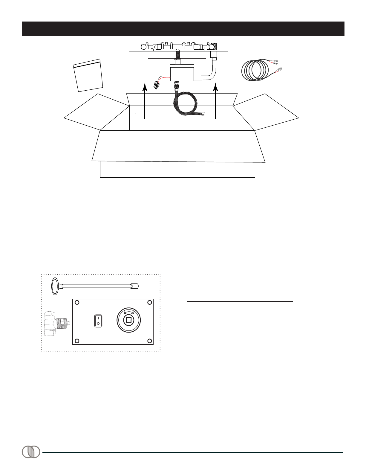
Manual Shut-off/Key Valve - Is there a manual shut-off or
key valve installed within 6-feet of the re feature? Did you
verify proper distance with local and national codes?
Purging a New Gas Line - Has the gas line been purged
of both air and possible debris? Any gas lines buried
underground must be pressure tested up to 60PSI to
ensure no leaks. After inspection is complete, most
plumbers will release pressure in the line at one location by
opening the manual ball/key valve. It is recommended to
release pressure by opening a ball/key valves associated
with all the re features. Example: There are four re
features on a job, open the rst key valve for a few
seconds, then close it. Then move on to the next key valve
and do the same thing until you have purged the debris out
of all four gas lines.
Injectors/Jets - Fire features using a Firegear Pro Series
brass burner incorporates individual injectors/jets on each
burner leg. All injectors are protected by a injector cover
that is provided with each burner. The injector hole size is
measured by using a numbered drill bit. An injector/jet
limits the amount of gas ow to the burner to ensure the
ame is a safe and reasonable height to not pose a risk to
people or property. Note: The Firegear Pro Series brass
burners DO NOT USE a primary, main burner orice like a
standard stainless steel burner. A steel nipple is installed in
place of the burner orice.
ELECTRICAL INFORMATION
Wire Gauge - Is the wire gauge correct? Wiring must be
12AWG or greater (solid or stranded) for all installations.
Note: It is recommended to ll the wire nuts with either
dielectric grease or silicone prior to installing the wire nut.
This will ensure a waterproof connection.
Why GFI circuit? A GFI is a type of circuit breaker which
shuts off electric power when it senses an imbalance
between the outgoing and incoming current. It protects the
house wires and receptacles from overheating and possible
re.
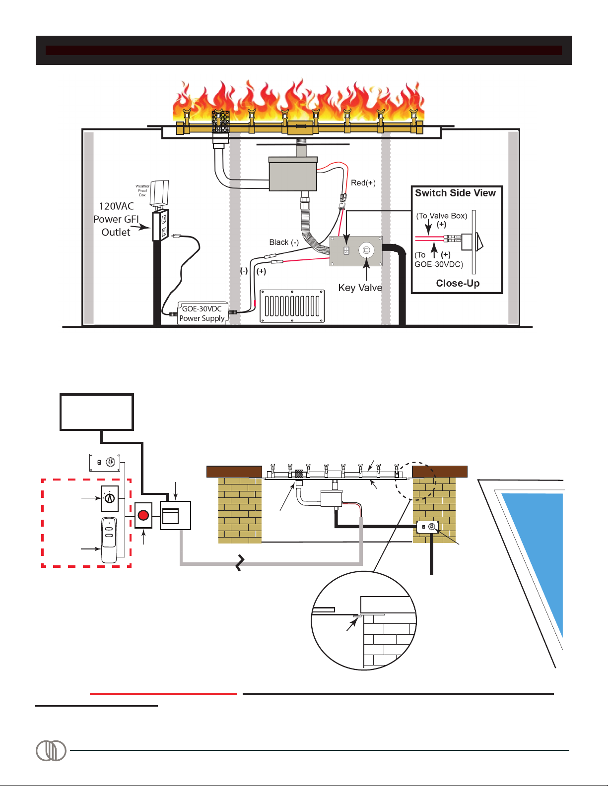
Power Supply - AMD Direct, Inc offers two power
supplies for use with AWS re pits. Each power supply
requires 120VAC power to operate and converts it to
30VDC to operate the gas valve. DO NOT CONNECT
120VAC DIRECTLY TO THE GAS VALVE WIRES -
DAMAGE WILL OCCUR.
The GOE-30VDC (supplied) is used for one re pit only,
installed 10-feet or greater from a pool or spa. This power
supply has a 3-foot power cord to plug into 120VAC
outlet and a 3-foot leads to connect to the gas valve on the
30VDC side.
The FG-PS30V320 (optional) model has an 8-foot power
cord and can be used for one or a maximum of four re
pits. The maximum distance the furthest re pit can be
from the power supply is 500-feet. In addition, the
FG-PS30V320 model enables a re pit to be installed within
5-feet of a pool or spa.
Bonding - Gas lines must be bonded AT EACH re pit.
(Refer to National Electric Code 2017 Section: 680.26(B).
MEDIA INFORMATION
Acceptable media placed over top of the burner:
Lava Rock 1”- 2” size
FG-LAVA-10 (10 LB)
FG-LAVA-40 (40 LB)
GL Glass ½” - ¾” size
Various colors are available
See Product catalog for details
Sold in 10LB jugss or 6 jugs to a case
GRL Reflective Glass ½” - ¾” size
Various colors are available
See Product catalog for details
Sold in 10LB jugs or 6 jugs to a case
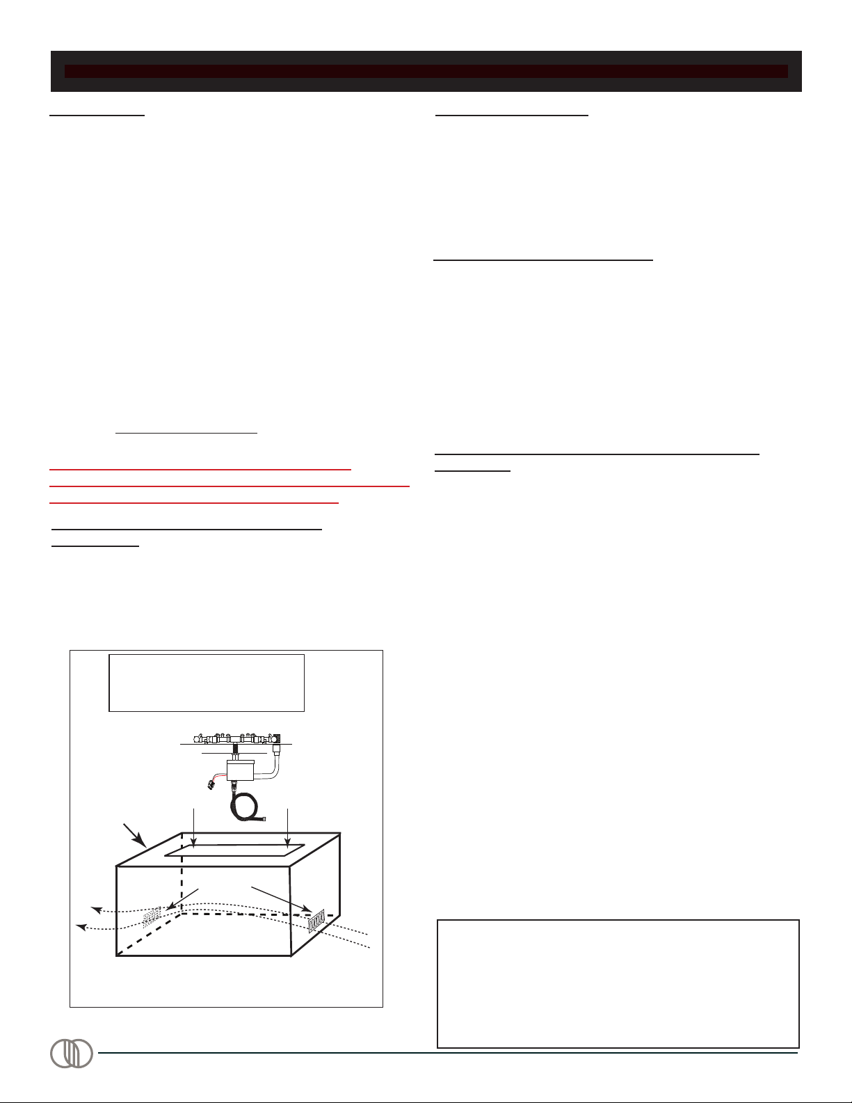
DRAINAGE INFORMATION
For any fire pit ABOVE ground level requires a drain line or
a way for water to exit the fire pit.
Note: The AWS system is not approved to be installed
BELOW ground level.
ALL PANS OR FLAT DISC’S MUST BE REMOVABLE
FOR SERVICE Pans or disc’s CAN NOT be installed in a
manner to prevent them from being removed for service.
Top coping material or top cap of re pit MUST NOT
overlap onto the pan or disc surface. Pan lip or disc edge
must be unobstructed so it can be lifted out of the re pit for
servicing.

REV. A Page 8
Sq. Pan Fire Pits with Brass Snowake Burner and (AWS) Ignition
PREPARING A NON-COMBUSTIBLE STRUCTURE FOR SINGLE INSTALL
POWER SUPPLY LOCATION
The GOE-30VDC power supply is to be installed inside the enclosure due to the wire length limitations. The power cord is
3-feet long the 30VDC leads to the valve are 3-feet long. See Fig. 4.
Fig. 4 Example of a single re feature install with power supply and switch contained within the enclosure, when
applicable.
Note: Must be 10-feet or more from a pool/spa for this installation. See additional illustration on pg. 9, Figs. 5-6.

REV. A Page 9
Sq. Pan Fire Pits with Brass Snowake Burner and (AWS) Ignition
INSTALLING BURNER PAN INTO ENCLOSURE
Fig. 5 Show typical wiring diagram with switch.
Timer
FG-1420-A OD
Remote Emergency
Stop
(Optional)
FG-PS-30V320
Low Voltage
Power Supply
Key Valve
Electrical Line
Gas Line
ON
OFF
or
Main Burner
Flat Pan
Pilot Burner
(Min. 12-gauge Max. 500’)
Flex Frame (shown in detail)
enables the ability to
remove the pan/disc
to service valve system
Flex
Frame
Optional ON/OFF
Controls
Note: Actual power supply must be
10-feet or more from the pool or spa
D
E
T
A
I
L
Pool
Control
Pool Certified Applications
(Fire Feature within 5-feet of pool or spa)
Pool
ON
OFF
ON
OFF
Key Valve
& Switch
Fig. 6 Shows any re feature installed within 5 feet of a pool or spa requires FG-PS-30V320 power supply (purchased
separately). DO NOT USE THE GOE-30VDC. FG-PS-30V320 power supply can be installed up to a maximum of
500-feet away from re pit.

REV. A Page 10
Sq. Pan Fire Pits with Brass Snowake Burner and (AWS) Ignition
Carton Contents
Hardware
Bag
Burner Pan
Valve
Box
REMOVING PARTS FROM CARTON
CONTROL PANEL MOUNTING PLATE
Fig. 4 Removing contents from carton.
The control panel mounting plate is pre-assembled at the
factory with the key valve and ignition switch. On the back
of this manual is a template for use to cut an opening for
the mounting plate. Once you have determined the location
of control panel mounting plate install the gas connections
and Piezo wires as shown in Fig. 4, page 8 and secure all
connections.
CAUTION: Use dielectric grease on all wire nut connec-
tions and ¼” connectors to prevent moisture issues from
the outdoor environment.
The AWS system is polarity sensitive. There is a red
sleeve attached to the positive (+) side of the GOE-30VDC
adapter. The red power wire from valve connects to on
side of the rocker switch. See Fig 5. on page 9.
Carefully install the re pit into the prepared enclosure,
connect the gas line and wire according to the gure
drawings in this manual.
The re pit comes assembled and only minimal wire
connections and gas hook up is required after it is installed
into the enclosure.
Open carton and remove contents. Inspect for any damage
or missing parts. The hardware bag includes the key valve
parts shown below in Fig. 8.
Note: Check for any gas leaks after gas is connected and
turned ON.
Hardware Bag
(included with re pit)
ON
OFF
Fig. 8 Hardware bag contents.

REV. A Page 11
Sq. Pan Fire Pits with Brass Snowake Burner and (AWS) Ignition
INSTALLATION OF MEDIA INTO BURNER PAN
Install lava rock into the burner pan. Ensure the lava rock is
a minimum of 1-inch diameter for proper operation.
Note: Do not pour Lava Rock directly from bag. It should
be placed naturally and NOT packed in tight. Loose tting
is important to ensure robust ames. Placing the lava rock
in the pan by hand, ensures no excessive dust from bag
lays in the bottom of pan and potentially plugs the burner
port holes or the pan weep holes. DO NOT BLOCK
INJECTORS WITH MEDIA.
IF USING AMD DIRECT, INC GL GLASS OR GLR
REFLECTIVE GLASS, ENSURE THE MEDIA DOES NOT
BLOCK THE INJECTOR HOLES.
IMPORTANT: DO NOT PLACE ROCK OVER TOP OR
UNDER THE PILOT SCREEN COVER. The screen must
be free of any debris to ensure proper lighting of burner
and good ame sense (See Fig. 11).
Cover the burner completely with media but do not make
the depth greater than 1-inch over-top of the burner
port holes.
Do NOT cover the top of mesh pilot hood with any rock or
glass. It must be free an any debris to operate properly.
Lava Rock Lava Rock
Lava Rock
Screen Cover
Pilot
Screen
Cover
Fig. 11 Media placement around pilot hood.
Acceptable media to be placed over top of the burner:
Lava Rock Min.1”- 2” size
FG-LAVA-10 (10 LB)
FG-LAVA-40 (1 CUBIC FOOT)
GL Glass Min. ½” - ¾” size
Various colors are available
See Product catalog for details
Sold in 10LB jugs or 6 bags to a case
GRL Reflective Glass
Min. ½” - ¾” size
Various colors are available
See Product catalog for details
Sold in 10LB jugs or 6 bags to a case
FINAL PREPARATION
Injector/Jets
Hoods
Groove around
the injector
Bead around
the hood
HOOD
Install the hood/rain shields over top of each injector of the
pro brass burner by sliding it into position. Use the bead in
the lower section of the hood, and align it with the groove in
the injector, until it snaps into place. See Fig. 9. Rotate the
hood to ensure it is protecting the injector opening from the
elements (i.e. rain, dirt or media). See Fig. 10 for proper
alignment. Note: If there is no detent in the injector, ensure
the hood is ½” from the base of the injector to the bottom
edge of the hood.
INJECTOR HOOD/RAIN SHIELD INSTALLATION
Fig. 9 Installing injector hoods.
Fig. 10 Correct placement of injector hoods.
1/2”
HOOD
INJECTOR
CAUTION: It is imperative the “open side” of all hoods
covering the injectors/jets are installed facing downward.
Because the hoods can be removed or turned, the
orientation is extremely important to protect the injector or
jets from dust, dirt or rain. See detail in Fig. 10.
WARNING: Failure to orient the hoods in the
proper position on the burner tube will void
the manufacturer warranty.

REV. A Page 12
Sq. Pan Fire Pits with Brass Snowake Burner and (AWS) Ignition
CAUTION: Children and adults should be alerted to the hazards on high surface temperatures and should stay away to
avoid burns or clothing ignition. Young children should be carefully supervised when they are in the area of the appliance.
WARNING: Do not use this appliance if any part has been under water. Immediately call a qualied service technician
to inspect the appliance and to replace any part of control system and any gas control, which has been under water.
OPERATION & LIGHTING
SAFETY WARNINGS
1. Never leave the re pit unattended during operation.
2. Clothing or other ammable materials should not be placed on or near the appliance.
3. Any guard or other protective device removed for servicing the appliance must be replaced prior to operating the
appliance.
4. Installation and repair should be done by a qualied service person. The appliance should be inspected before
use and at least annually by a qualied service person. More frequent cleaning may be required as necessary. It
is imperative the control compartment, burners and circulating air passageways of the appliance be kept clean.
5. Inspect the fuel supply connection before each use of the appliance.
6. Temporary storage of this appliance indoors is permissible only if it has been disconnected from its fuel supply
(Natural or LP gas line).
WARNING
1. This appliance is hot when operated and can cause severe burns if contacted.
2. Do not burn any solid fuels in this appliance.
READ ALL LIGHTING INSTRUCTIONS BEFORE ATTEMPTING TO LIGHT FIRE PIT
CAUTION: ENSURE YOU HAVE LEAK TESTED THE FIRE PIT BEFORE OPERATING.
WARNING: Do not stand over re pit during ignition or operation due to high surface temperatures.
LIGHTING INSTRUCTIONS
TURNING ON FIRE PIT/FEATURE
Prior to turning the re pit ON, visually inspect the re pit to ensure debris such as leaves or other combustible materials
have not collected on top of the re pit, which could burn and emit embers once the re pit is turned ON. At the same
time, ensure anyone standing close to the re pit is aware you are turning it ON and steps away, at a safe distance prior to
lighting.
The ignition sequence is as follows:
1. Turn the manual key valve to the ON position.
2. Turn the re pit ON by pressing the ON button of the rocker switch. The hot surface igniter will heat up and begin to
“glow” in approximately 10 seconds.
3. Once the hot surface igniter heats up, the pilot gas valve opens, a “click” is heard, and gas is released to the burner,
lighting the re pit.
The entire ignition sequence ignites within 20 seconds or less. If not, press the OFF button of the switch and wait 5
minutes before trying again.
TURNING OFF FIRE PIT/FEATURE
1. Turn the re feature OFF by pressing the OFF button of the rocker switch or timer if applicable.
2. If you are no longer burning the re pit until another time, we recommend turning the key valve to OFF position.

REV. A Page 13
Sq. Pan Fire Pits with Brass Snowake Burner and (AWS) Ignition
AWS REPLACEMENT PARTS
12
6
5
Drawings not to scale.
4
7
G
A
S
P
R
E
S
S
U
R
E
R
E
G
U
L
A
T
O
R
89
10
12
13
14
17
OUT
3
15
16
11

REV. A Page 14
Sq. Pan Fire Pits with Brass Snowake Burner and (AWS) Ignition
1 11” Pro Brass Snowake Burner - Natural Gas 1 10900
1A 11” Pro Brass Snowake Burner - Propane Gas 1 10901
2 18” Pro Brass Snowake Burner - Natural Gas 1 10902
2A 18” Pro Brass Snowake Burner - Propane Gas 1 10903
3 25” Pro Brass Snowake Burner - Natural Gas 1 10904
3A 25” Pro Brass Snowake Burner - Propane Gas 1 10905
4 32” Pro Brass Snowake Burner - Natural Gas 1 10906
4A 32” Pro Brass Snowake Burner - Propane Gas 1 10907
5 20” Square Stainless Drop In Pan 1 PAN-SS20S
5A 26” Square Stainless Drop In Pan 1 PAN-SS26S
5B 32” Square Stainless Drop In Pan 1 PAN-SS32S
5C 38” Square Stainless Drop In Pan 1 PAN-SS38S
6 ½” Flex Gas Line (46-inch Length) 1 T-200-9898-46
7Brass Burner Support & Hardware Bag 1 10850
8 Ignition Control Box (Valve box only) 1 FG-ICB
9 Pilot Burner Assembly (Complete pilot assembly and wires) 1 FG-PBA
10 AWS Power Wire to Valve 1 10626
11 Heat Shield 1 FG-HEATSHIELD
12 Weatherproof Rocker Switch 1 WP-SWITCH
13 Key Valve Faceplate and Switch 1 78130
14 ½” OD Flare to 3/8” MIP Fitting 1 U1-8C-S
15 ½” NPT Female to ½” Male Flare Fitting 1 U3-8D-S
16 ½” Flare to ½” MIP 90° elbow 1 49-88
17 LP Regulator with 32” Hose - NOT FOR USE WITH NATURAL GAS 1 FG-32LPHRK
Item Description
AWS REPLACEMENT PARTS LIST
Part #
Qty.
OUT
Valve Box Reference
2-pin Igniter Connector
2-pin Thermopile Connector
Flared Pilot Connection
Compression Pilot Connection

REV. A Page 15
Sq. Pan Fire Pits with Brass Snowake Burner and (AWS) Ignition
TROUBLESHOOTING
Sequence of Operation
Fire Feature Turned ON
First Pilot with Hot Surface Igniter
Heats Up and Glows (Approx. 10 seconds)
Secondary Pilot Opens; “Click” is Heard;
Gas is Released to Burner
Fire Feature is Lit Until
Turned OFF
The system is designed to relight itself if blown out. It will
try (3) times to relight before it goes into a “hard” lock out.
Then it must be turned OFF and back ON to reset it .
• No Power - Check for power at the re feature(s). Conrm proper power is being supplied to the system. 30VDC
from power supply to valve and 120VAC where power supply is plugged into.
• Defective Controller - If for some reason someone connected 120VAC power directly to the gas valve, the controller
inside the valve box will be damaged. It this happens, a burned electrical smell might be present.
• Connector Not Plugged In Correctly - Check the 2-Pin connector from pilot to the gas valve, Ensure it is plugged
into place with the locking latch.
• Pins Not Secure - Check the pins inside the 2-pin connector, ensure they are not loose. If loose push them back in
until tight and try system again.
• Possible Defective Igniter - Unplug the igniter and check resistance across the two pins inside the plastic housing
coming from the pilot assembly. Use a multi-meter to check resistance. Resistance should be 2.6 - 3.4 ohms. If no
resistance or resistance greater than 8 ohms indicates a defective igniter.
1. Turned the Fire Feature ON... but nothing happens.
2. Glow Plug does not glow.
START UP ISSUES

REV. A Page 16
Sq. Pan Fire Pits with Brass Snowake Burner and (AWS) Ignition
• Insufcient Power - If the glow plug is not getting enough power, it will not get ignite the gas.
• Thin Wire - The recommended minimum wire gauge is 12AWG . If wire is less than 12-gauge there may not be
enough power to get the igniter hot enough.
• No Gas - Was the gas line purged of air? If gas line was not bled it may take a while before the gas gets to the re
feature.
• Manual Shut Off Valve - Is the manual shut-off or key valve open?
• Debris - Debris can get trapped inside the screen of the gas valve. Excessive amounts of pipe dope or Teon tape
can restrict gas ow.
• Debris in Pilot Burner - New gas lines, until bled, have air and will have some debris. Ensure gas it turned OFF and
electrical is unplugged. Remove the two brass tting from the gas valve, then use “canned air” to blow through the
pilot outlets.
• Wrong Pilot Orice - If the wrong pilot orice is installed into the primary pilot it will not light.
• Oxygen Starvation - To ignite gas we need oxygen, fuel and a heat source. If the pilot assembly is buried underneath
the glass media or lava rock it will not allow the pilot to light.
• Weak Igniter - In some cases, from the manufacturer’s glow plug will have slight difference in assembly which can
cause some igniter’s burn hotter than others. These are tested before they are sent to customers but sometimes a
weak one can get out. If this occurs, the symptom will always be the same - inconsistent or no ignition at all. In this
case, replace the pilot burner.
• Valve Box Installed Backwards - Check the label on the gas valve box and ensure the burner is connected to the
OUTLET side of the gas valve box.
• Thermopile Pins Not Secure - Check the pins in the pilot burner connector, remove it from the gas valve and check
for loose pins. If loose, push inward until tight and try again. If this happens, the glow plug will stay ON for up to 30
seconds before turning OFF. It normally shuts off in about 5 seconds.
• Defective Thermopile - Thermopile’s rarely go bad however if a product is used consistently for extended periods of
time a thermopile can get too hot (like a blow torch) and eventually cause it to swell. Simply loosen the thermopile
from the pilot assembly and slide it out. If it will not slide out because is it too tight, then it will need to be replaced.
• Debris - Debris can get trapped inside the screen of the gas valve. Over time rust and other debris can restrict the
gas ow on the Outlet screen of the valve that can partially or sometimes even stop the ow. Inspect the screen,
remove it and clean it then replace it.
• Defective Controller or Main Gas Valve - If you have inspected the thermopile connections and no debris is on the
controller or gas valve; checked the power, then the gas valve or controller may be defective and will need replaced.
3. Glow Plug Glows, But Does Not Ignite the Gas
4. Pilot Lights, But No Flame to the Main Burner
5. Fire Features Lights... Turns OFF Within A Few Seconds...
and Restarts Again (Keeps repeating this sequence)
• Gas Volume Insufcient - When initially turning ON the re feature pilot is lit and there is enough gas for the pilot to
light, however once main gas valve is turned ON, the ow of gas to pilot drops not providing enough gas to keep the
thermopile hot enough therefore the pilot will drop out and relight. This is usually caused by insufcient Gas Volume
and can be caused by installing gas pipe too small to deliver proper amount of gas or by installing a Manual Gas
Shutoff (Ball valve or Key Valve) with a capacity that is too small to allow enough gas to pass through to the feature.
• Main Burner Orice Not Installed - Ensure the correct orice is being used. If using LP gas it should have vent holes,
Natural gas does not. See Fig. 4, page 8. The orice/air mixer restricts the amount of gas owing to the Main Burner.
This restriction ensures that not ALL the gas will ow to the Main Burner, so there is still enough gas left for Pilot
Burner.
• Oxygen Starvation - to ignite gas we need oxygen, fuel and a heat source. If the pilot assembly is buried underneath
the glass media or lava rock it will not allow the pilot to light.
• Defective Thermopile - See Symptom 4 above for Defective Thermopile.
• Defective Controller – If your plumbing is supplying enough gas, the Main Burner orice is installed, the Pilot Burner
is getting plenty of air and the Thermopile is not defective the only thing left is a Defective Controller inside the valve
box. If you have a Defective Controller the only way to x it is to replace it.
TROUBLESHOOTING

REV. A Page 17
Sq. Pan Fire Pits with Brass Snowake Burner and (AWS) Ignition
6. Fire Feature Cycles (Turns On and Off) Every Few Minutes
• Gas Volume Insufcient – See symptom 5 page 21 for “Gas Volume Insufcient” for detailed explanation.
• Oxygen Starvation (Pilot Burner) – See symptom 5 page 21 for “Oxygen Starvation” for detailed explanation.
• Defective Thermopile – See symptom 4 page 21 for “Defective Thermopile” for detailed explanation
• Defective Controller – See symptom 5 page 21 for “Defective Controller” for detailed explanation
7. Main Burner Flame Lazy/Small or Flame NOT Spread Out Over Entire Burner
• Gas Volume Insufcient – See symptom 5, page 21 for “Gas Volume Insufcient” for detailed explanation
• Debris On Inlet Screen; Valve Box – See symptom 3, symptom 4, page 21 for “Debris on inlet screen for detailed
explanation
• Debris On Outlet Screen; Valve Box – See symptom 4, page 21 for “Debris on Outlet Screen for detailed explanation.
• Obstruction In Plumbing Between Gas Valve Outlet and Main Burner – If your plumbing was sized correctly to deliver
the proper amount of gas and the screens in the valve box are clean, inspect the plumbing between the valve and the
burner for obstructions. Also, inspect inside the burner inlet to ensure no obstructions in there as well.
8. Main Burner Flame “Flares Up” Every Few Minutes
• Fire glass/Media Layer too Thick – Fire glass/media comes in different sizes. Use only ½” - ¾” diameter. If you put
a thick layer of re glass/media on top the burner, over 1” in depth; there is a good chance some of the gas will get
“trapped” within the media while the feature is ON. When this happens, the trapped gas in the re feature ignites and
you see the “Flare Up” effect. Remove some of the re glass/media from the burner to see if this xes the problem.
• Gas Leak – Natural Gas is lighter than air therefore when released into the atmosphere it rises. If you have a Natural
Gas re feature and there is a gas leak the Natural Gas will rise to the top of the feature. Once it encounters the ame
a are up will occur. Propane is heavier than air so if there is a gas leak when using propane the gas will fall into the
bottom of the feature. That is why it is REQUIRED drainage/ventilation be installed at the bottom of the feature when
using Propane. You do NOT want Propane accumulating inside the re feature.
9. Turn the Feature OFF…but a Small Flame Continues to Burn in the Pilot Burner
• Leak in the Pilot Burner Gas Valve – When debris enters the gas valve by way of either the Inlet or outlet there is a
chance some of that debris will enter the Pilot Burner Gas Valve and contaminate the seal inside the valve. If this
occurs, the possibility exists the valve will not seal properly when turned OFF thereby allowing a small amount of gas
to ow even after being turned OFF. Often this will result in a small ame that continues to burn in the Pilot Burner
after the feature has been turned OFF.
• Leak in the Main Burner Gas Valve - when debris enters the gas valve by way of either the Inlet or Outlet there is a
chance some of that debris will enter the Main Burner Gas Valve and contaminate the seal inside the valve. If this
occurs the possibility exists the valve will not seal properly when turned off thereby allowing a small amount of gas
to ow even after turned off. Often this will result in a small ame that continues to burn on the Main Burner after the
feature has been turned OFF.
10. Turn the Feature OFF…but Small Flames Continue to Burn Out the Main Burner
SHUTDOWN ISSUES
TROUBLESHOOTING

REV. A Page 18
Sq. Pan Fire Pits with Brass Snowake Burner and (AWS) Ignition
1. The re pit should be inspected and cleaned before initial use, at least annually, by a qualied eld service person.
2. Any component that is found faulty must be replaced with an approved component.
3. Any tampering or modifying with the re pit is dangerous and voids all warranties.
4. During winter months in cold climates and various seasons of operation the re pit may be affected by weather
conditions. It is recommended to use a ventilated cover over top of your re pit to protect it from humid/rainy weather
conditions when not in use. Heavy rains/downpours could affect the re pit operation if not covered; if this occurs
ensure you allow the re pit time to dry out before attempting to operate. NOTE: If a combustible type cover is used
over the re pit when not in use be sure to remove it before operation to prevent a severe safety hazard.
5. Over time stainless steel parts can discolor when heated, usually a golden or brown hue. This discoloration is normal
and does not affect the performance of the appliance.
Brass Burner Maintenance Information:
• Dust in injector - Use compressed air from aerosol can or compressor.
• Check for bug nests or stubborn debris - replacement where necessary.
Note: Always use safety equipment including but not limited to SAFETY glasses or goggles when using
compressed air and consider a disposable mask for particulate.
FIRE PIT MAINTENANCE

REV. A Page 19
Sq. Pan Fire Pits with Brass Snowake Burner and (AWS) Ignition
OPTIONAL ACCESSORIES
The following accessories are available from your local AMD Direct, Inc dealer/distributor.
Each accessory comes with a separate installation manual. Read each instruction thoroughly before installing.
Paver Control Panels
PAVER-CP-AWS AWS systems
Vent Kits
Provide 18 sq. in of ventilation per side
of enclosure)
Model: VENT-KIT-6X12SS
Model: PAVER-VENT-4-LNTS
Model: PAVER-VENT-6-LNTS
Media
Lava Stones 1” to 2” size (50lbs.)
Models: FG-LS50 (Bag)
Lava Rock 1” to 2” size
Models: FG-LAVA-40 (Bag)
FG-LAVA-10 (Bag)
See catalog for various colors.
Glass Windshields
See catalog for a windshield to t your
application.
FLEXFRAME
Universal brackets to support re pit
when using paver blocks or other non-
combustible enclosures.
Model: FLEXFRAME-SS (2 piece)
Model: FLEXFRAME-SS3 (3 piece)
Pool/Spa (Water Installations)
Model: FG-AWS-PS-30V320
Power supply for one or up to (4) re
features near a pool/spa.
Must order any Firegear Outdoor Match
Throw (AWS) Burning Spur re pit to
use with kit listed above (sold sepa-
rately).
Emergency Stop
(Emergency shut-off valve)
Model: FG-EMER-STOP
(includes J-Box and
weatherproof cover)
LP Conversion Kit
Model: FG-AWS-PBO-P
Contains primary pilot orice
(FG-PBO-LP) to convert Natural gas
pilot to LP gas.
Note: In addition, the main burner
MUST be changed to LP. See parts
section (purchased separately).
MSI (Manual Spark Ignition) kits are not
available for any brass burners.
No LPK conversion kits are available
for brass burners.
Timer
(Mechanical gas timer)
Model: FG-TIMER- 2HR
* Includes weatherproof J-box and cover
NOTE: See the AMD Direct, Inc catalogue for other accessories also available.
Manual changes often occur, ensure to check the AMD Direct, Inc
website for any recent updates and warranty information.
FOR TECHNICAL SERVICE, CALL:
AMD Direct, Inc
17322 Gothard St.
Huntington Beach, CA 92647
Web Site: www.amddirect.com
(800) 966-8126

REV. A Page 20
Sq. Pan Fire Pits with Brass Snowake Burner and (AWS) Ignition
FIREGEAR LIMITED WARRANTY - 2022
Firegear Outdoors hereby warrants to the end user that products will be free from material and workmanship
defects that prevent safe and correct operation of the product. The warranty commences from date of sale to
the end user for the following period:
CONSUMER RESIDENTIAL APPLICATIONS – MANUFACTURED AFTER 12/02/2019
• BURNER SYSTEMS, BURNERS, COMPONENTS AND ACCESSORIES
• LIFETIME WARRANTY ON CONSTRUCTION AND MANUFACTURER DEFECTS
• LIFETIME WARRANTY - STAINLESS STEEL BURNERS AND PANS
• LIFETIME WARRANTY - BRASS BURNERS
• FIVE (5) YEAR WARRANTY - GAS VALVE, SPARK IGNITER, PILOT ASSEMBLIES
• FIVE (5) YEAR WARRANTY - AWS ELECTRONIC IGNITION SYSTEMS (24VAC, 30 VDC)
• FIVE (5) YEAR WARRANTY - TFS/TMSI ELECTRONIC COMPONENTS
• FIVE (5) YEAR WARRANTY – MT COMPONENTS (KEY VALVE)
• FIVE (5) YEAR WARRANTY - REFRACTORY GAS LOG SETS
• FIVE (5) YEAR WARRANTY - READY TO FINISH/ANF FIRE PIT ENCLOSURES
• FIVE (5) YEAR WARRANTY – SKYTECH MANUFACTURED OPTIONAL CONTROLS
OUTDOOR FIREPLACE – KALEA BAY
• LIFETIME WARRANTY - CONSTRUCTION AND MANUFACTURER DEFECTS
• LIFETIME WARRANTY - STAINLESS STEEL COMPONENTS
• FIVE (5) YEAR WARRANTY - GAS VALVE, PILOT ASSEMBLY, POWER SUPPLY, CONTROLS
• FIVE (5) YEAR WARRANTY – SKYTECH MANUFACTURED OPTIONAL CONTROLS
SANCTUARY SERIES – GFRC FIRE FEATURES
• THREE (3) YEAR WARRANTY - GFRC STRUCTURE
• REFER TO THE APPROPRIATE BURNER SYSTEM FOR WARRANT
WARRANTY COVERS MANUFACTURING DEFECTS OR STRUCTURAL FAILURE. SMALL STRESS CRACKS
AND SURFACE CRAZING ARE A NATURAL OCCURRENCE IN GFRC PRODUCTS AND NOT COVERED BY
WARRANTY.
READY TO FINISH/ANF ENCLOSURES
• FRAME – LIFETIME WARRANTY ON CONSTRUCTION AND MANUFACTURER DEFECTS
ACCESSORIES
• LIFETIME WARRANTY - CONSTRUCTION AND MANUFACTURER DEFECTS
• LIFETIME WARRANTY - STAINLESS STEEL COMPONENTS (LIDS, STAINLESS STEEL COVERS)
• ONE (1) YEAR WARRANTY – ESTOP1-OH, ESTOP2-5H WINDSHIELDS, HOSES AND REGULATORS
Other manuals for Pro Series
7
This manual suits for next models
8
Table of contents
Other AMD DIrect Outdoor Fireplace manuals
Popular Outdoor Fireplace manuals by other brands

Gilbert & Bennett
Gilbert & Bennett FBCIWOVEN-BZ user manual

PEAKTOP
PEAKTOP HF36501AA-EU Use and care guide

Landmann
Landmann OC-I-490 Assembly and operating instructions

Jaclyn Smith
Jaclyn Smith FP-K14 owner's manual

Costway
Costway NP11018 Assembly instructions

Coleman
Coleman 5056-707 Assembly and instruction sheet

UKIAH
UKIAH TAILGATER manual

Hanover
Hanover Monaco MON5PCSW4DFP Assembly instructions

Backyard Creations
Backyard Creations ST. CROIX HD WT17YL Safety manual

Lund
Lund 99702 manual

Mayer Barbecue
Mayer Barbecue HEIZA MGK-200 Aassembly Instructions

Planika
Planika Galio Corten Black Automatic Installation and user manual