PARTNER/STEPPER™AUGMENTATIVE COMMUNICATION DEVICES
INSTRUCTION SHEET
Congratulations on your purchase of the STEPPER™ a Multi-Message augmentative communicator. THE STEPPER IS AN ENTRY-
LEVEL AUGMENTATIVE COMMUNICATOR THAT OFFERS HIGH QUALITY,RELIABLE PERFORMANCE AND MANY IMPORTANT FEATURES FOR A
VERY LOW PRICE.THE STEPPER IS MANUFACTURED TO THE HIGHEST COMMERCIAL STANDARDS TO PROVIDE MANY YEARS OF RELIABLE
OPERATION.WE FULLY GUARANTEE THE STEPPER’S OPERATION FOR A FULL YEAR,INCLUDING PARTS AND LABOR.*
DISTINCTIVE FEATURES OF THE STEPPER
60 SECONDS OF RECORDING TIME.
REVERSE SWITCH TO STEP BACKWARDS.
REPEAT SWITCH TO CONTINUALLY REPEAT ANY MESSAGE STORED.
RESET SWITCH TO START FROM THE BEGINNING.
IN ADDITION TO THE BUILT-IN MICROPHONE,SPEAKER AND RECORD SWITCH,1INPUT &1OUTPUT JACK IS PROVIDED FOR EXTERNAL SWITCH HOOK
UPS.
DROP RESISTANT,ABLE TO WITHSTAND ROUGH HANDLING.
WATER RESISTANCE FOR EASY CLEANING.
THE SHATTERPROOF CASE IS MADE OF A HIGH IMPACT PLASTIC.
LIGHT WEIGHT AND PORTABLE (LESS THAN 1LB.)
THE STEPPER GIVES YOU “REAL-VOICE”HIGH QUALITY AUDIO REPRODUCTION.
MESSAGES CAN BE STORED FOR UP TO 100 YEARS WITH NO POWER.
INTERCHANGEABLE OVERLAY,COMPATABLE WITH MAYER JOHNSON BOARDMAKER™ SOFTWARE.
*SEE WARRANTY AGREEMENT FOR DETAILS.
GENERAL OPERATION:
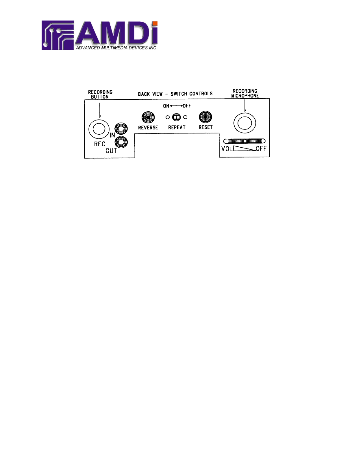
All controls are located on the back of the STEPPER (see diagram –BACK VIEW).
The STEPPER augmentative communicator is a self-contained Multi-Message communication device, which permits the user to record and
playback any number of messages that can be stored in 60 seconds of recording time. A graphic overlay (picture cards) can be easily changed by
simply sliding the overlay between the housing grid and the message square through the slot on the top of the grid. Simple to operate, just turn
the unit on, adjust the volume and push the picture to activate the message or messages.
BATTERY INSTALLATION
1. Make sure that the STEPPER is turned off. Set VOLUME control switch fully to the right, until it clicks off.
2. Turn the STEPPER over and lay the front of the unit on a flat stable surface.
3. To gain access to the battery compartment and expose the batteries, remove the two screws holding down the plastic battery
cover on the bottom of the unit.
4. Remove the old batteries and discard them in accordance with your local recycling laws.
5. Install the new batteries observing the proper polarity and using 4 new AAA batteries.
6. Then replace the battery compartment cover by placing the cover over the access hole and tighten down the two screws. Insure
the battery cover is secure.
RECORD OPERATION:
Note: It is important during any recording operation that the built in microphone located at the back of the STEPPER is clear and open.
1. Turn the STEPPER ON. Turn the VOLUME control switch until it clicks ON.
2. Set the VOLUME control, turning to the left, until it reaches the center of the range.
3. Depress and hold in the built-in record button. The record switch must be engaged for the entire recording process.
4. Press and hold down the message square on the face of the STEPPER and then begin to say your message into the built-in
microphone located at the back of the STEPPER (see diagram –BACK VIEW). For the best results, you should speak directly
into the microphone and be about 6 to 9 inches away from it in a quiet room.
5. To record the next message, DO NOT RELEASE THE RECORDING BUTTON, release the message square.
6. Press and hold down the message square again and begin saying the next message.
7. Continue this process for the remainder of all the messages.
8. Release the recording button after all the messages have been stored. To insure that the messages have been stored properly,
release the message square first and then the recording button last.
INPUT AND OUTPUT JACKS:
The STEPPER comes fully equipped with 2 external control jacks (see diagram –BACK VIEW), 1 - Input and 1 - Output. The two control jacks
on the back of the unit correspond to the message square on the front of the STEPPER.
INPUT JACK:
The first jack labeled IN on the back of the STEPPER is an Input jack (see diagram –BACK VIEW for
jack locations). It is used for activating the message square through an external switch. When the switch
plugged into the Input jack is activated, the messaged programmed into the message square will play.