AMEC AIS SART PLOMO-500 User manual


I
COPYRIGHT
The entire contents of this instruction manual, including any future updates, revisions, and
modifications, shall remain the property of AMEC at all times. Unauthorized copies or
reproduction of this manual, either in part or whole, in any form of print and electronic media, is
prohibited. The contents herein can only be used for the intended purpose of this manual.
DISCLAIMER
AMEC is devoted to publish and maintain this product manual. As we continue to improve our
AIS products to satisfy all customers’ needs, information in this document is subject to change
without notice. AMEC does not make any representations or warranties (implied or otherwise)
regarding the accuracy and completeness of this document and shall in no event be liable for
any loss of profit or any commercial damage, including but not limited to special, incidental,
consequential, or other damage.
Contact us at:
Technical Support:
Sales & Marketing:
ALLTEK MARINE ELECTRONICS CO., LTD
7F, No. 605, Ruei-Guang Rd., Neihu, Taipei, Taiwan 114
TEL: +886 2 2627 1599
FAX: +886 2 2627 1600
www.alltekmarine.com
(Your Local Dealer/Agent Warranty Stamp)
Version 1.24

II
The equipment said in this manual must only be used to which it was designed. Improper
operation or installation may cause damage to the equipment or injury to personnel. AMEC will
not incur any liability of equipment damage or personal injury due to improper use or
installation of the equipment. It is strongly recommended to read this manual and the following
safety instructions before proceeding to installation or operation.
SAFETY INSTRUCTIONS
ELECTRICAL SHOCK HAZARD.
Do not open the case of the
equipment. Only qualified
personnel could work on the interior
of the equipment.
WARNING
TURN OFF THE POWER IMMEDIATELY IF
WATER LEAKS INTO THE EQUIPMENT
OR OBJECT DROPS INTO THE
EQUIPMENT.
Continue operating the equipment could
cause electrical shock or fire. Contact your
nearest distributor for service.
DO NOT DISASSEMBLE OR MODIFY THE
EQUIPMENT.
Improper disassemble or modification could
cause electrical shocks, fire, or personal
injury.
WARNING
DO NOT PLACE ANY LIQUID-FILLED
CONTAINER ON TOP OF THE
EQUIPMENT.
Electrical shocks could be resulted if the
device is contaminated with liquid.
TURN OFF THE POWER
IMMEDIATELY IF THE EQUIPMENT IS
EMMITTING SMOKE OR FIRE.
Continue operating the equipment could
cause electrical shock or fire. Contact
your nearest distributor for service.
EVEN THOUGH THE EQUIPMENT IS
WATERPROOF, PLEASE AVOID
DIRECT CONTACT WITH RAIN OR
SPLASHING WATER.
Electrical shock or fire could be resulted
if water leaks into the equipment.
AVOID OPERATING THE EQUIPMENT
WITH WET HANDS.
Electrical shocks could be resulted if
operating with wet hands.
DO NOT CUT, SHORTEN OR
LENGTHEN THE SUPPLIED CABLES
BY AN APPROPRIATE SUPPLIER.
Improper change of cable length and
connector could cause failure of
transmitting signal.
WARNING!

III
FORWARD
Congratulations on the purchase of PLOMO-500 AIS SART. PLOMO-500 is strictly tested to
meet the rigorous demands of the marine environment. Unless improper use, installation,or
maintenance, the equipment should function properly at its optimum.
The operation instructions contained in this manual is applied only to PLOMO-500. AMEC and
the authorized local agent/dealer will not bear any responsibilities of damages resulted from
improper installation by any unauthorized agent/dealer.
We thank you for choosing our product and we wish you a bon voyage.

1
Table of Contents
I. COPY RIGHT & DISCLAIMER
II. WARNING & SAFETY INSTRUCTION
III. FORWARD
Page
1 AMEC AIS SART PLOMO-500 Introduction.........................................................1
1.1 AIS SART Brief ...............................................................................................................1
1.2 PLOMO-500 Overview...................................................................................................2
2 INSTALLATION............................................................................................................3
2.1 Items in the Package.....................................................................................................3
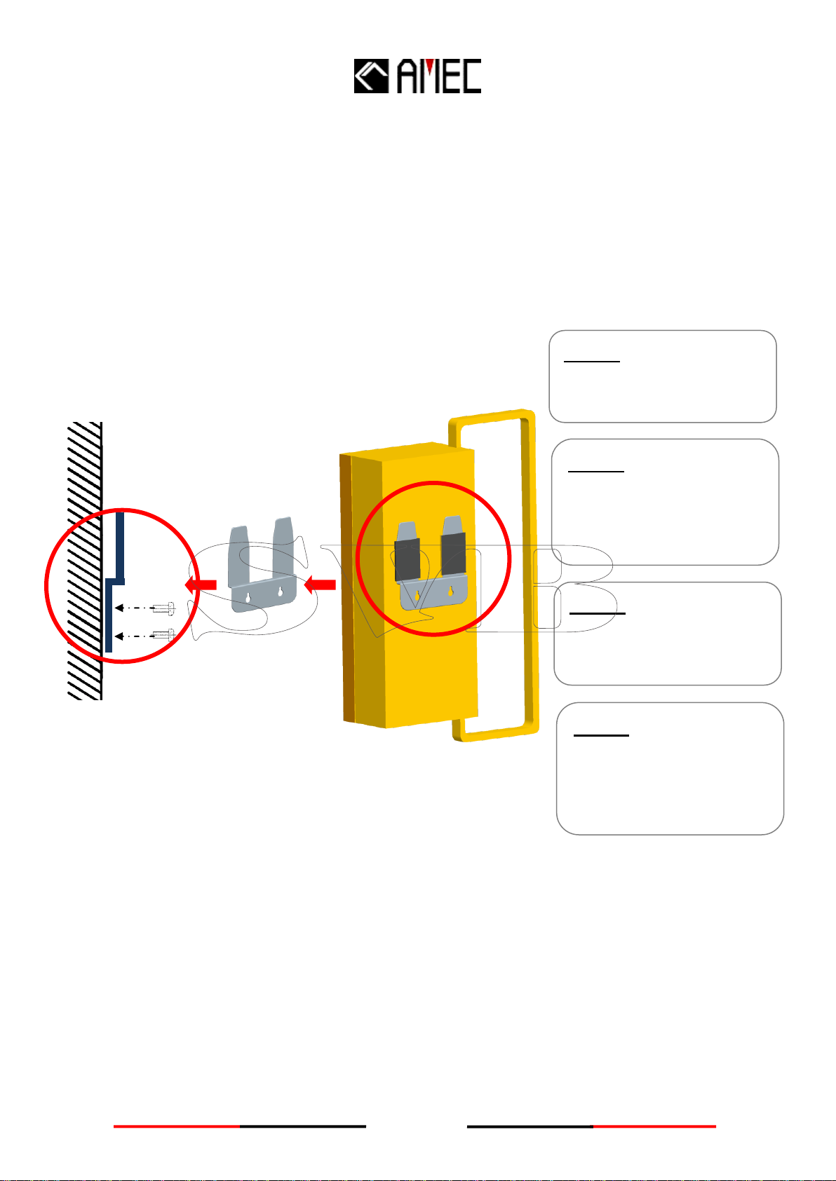
2.2 Mounting..........................................................................................................................4
3 OPERATION .................................................................................................................5
3.1 Emergency.......................................................................................................................5
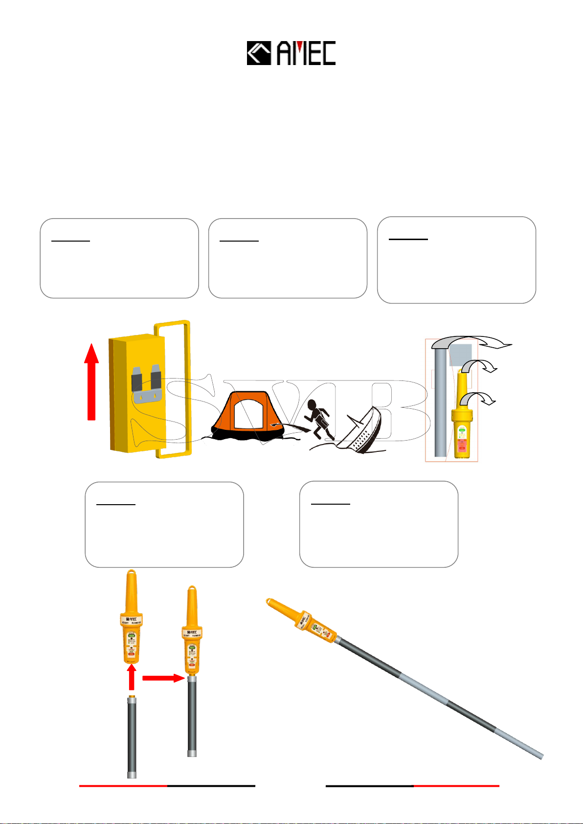
3.1.1 Deployment process......................................................................................................5
3.1.2 Activating process..........................................................................................................6
3.1.3 Mounting process...........................................................................................................7
3.1.4 De-activating Process ...................................................................................................8
3.2 Self-Test............................................................................................................................9
3.2.1 Before Testing:................................................................................................................9
3.2.2 Start Testing .....................................................................................................................9
3.2.3 Description of TEST LED............................................................................................10
4 Importance ................................................................................................................. 11
4.1 GPS Area........................................................................................................................11
4.2 Reception by AIS receiver.........................................................................................11
4.3 Maintenance..................................................................................................................12
4.4 Replacement .................................................................................................................12
4.5 Battery Disposal...........................................................................................................12
5 APPENDIX ..................................................................................................................13
5.1 Product Specifications...............................................................................................13
5.2 Dimensions....................................................................................................................15
6 AMEC WORLDWIDE WARRANTY........................................................................17
7 DECLARATION OF CONFORMITY.......................................................................19

1
1 AMEC AIS SART PLOMO-500 Introduction
1.1 AIS SART Brief
AIS SART is the latest SART (Search And Rescue Transponder/Transmitter), designed for
survivor location during search and rescue operations. From 1st of January 2010, AIS SART has
been adopted into the GMDSS (Global Maritime Distress Safety System, Figure 1.1)
regulations as an alternative to the traditional SART equipment, RADAR SART.
AIS SART provides more identification, such as position rather than RADAR SART during
search and rescue operation period. The transmitting frequency has been set as 161.975MHz &
162.025MHz in marine VHF channel.AIS SART combines two antennas, GPS and VHF, which
allows transmitting its latitude and longitude, message 1 and message 14 to AIS station.
Figure 1.1 SART in Global Maritime Distress Safety System (GMDSS)

2
1.2 PLOMO-500 Overview
AMEC has launched newlyAIS SART, PLOMO-500 which builds in the latest technology of
GPS receiver, sophisticated power-saving circuits design, lighter weight and easier installation
and operation.
Besides, PLOMO-500 provides the most user-friendly interface and allows crews or passengers
to shorten their operation time to transmit their location and SRM (Safety Related Message) to
any other AIS receiver device.
The key features of PLOMO-500 shows as follows:
Handing:
PLOMO-500 is designed for easy operation. It has a carry bag which contains all main body, 1
meter extension pole and 10 meters buoyant lanyard. The carry bag can be mounted and
hanged in the ship by wall-mount bracket. Users can easily understand the instruction printed
on the main body and bag in a very short time.
Figure 1-2 Carry bag of PLOMO-500
Robust & Waterproof Design
PLOMO-500 has been tested for more than 10 meters deep of water resistant and dropped in
the water from 20 meters without damage. Besides, it can be buoyant on the water and resist to
seawater, oil and sunlight.

3
Viewable Panel Design
PLOMO-500 has florescent backlight panel which allows users can read the operation button
and active button in twilight environment. Aside from that, the Flashing of Active mode is coding
in Morse Code “SOS”which is viewable in dark environment as well.
Easy Installation
The additional extension pole can extend length up to 1 meter and user only need to connect
and rotate with PLOMO-500 and extend pole to 1 meter.
2 INSTALLATION
2.1 Items in the Package
The PLOMO-500 is typically delivered with standard package as shown in Table 2-1. It is also
illustrated in Figure 2-1 (except manual).
Table 2-1 Standard equipment list
No.
Description
Qty
1
AMEC PLOMO-500 AIS SART
1
2
Manual
1
3
Installation
Kit
Carry Bag
1
1M Extension Pole
1
10M buoyant lanyard
1
Wall-Mount Bracket
1
Screw M4x20
4
Figure 2-1 Standard package
1. PLOMO-500 x1
2. Carry Bag x1
3. 1M Extension Pole
(with bottom cover)
4. Wall-Mount Bracket
5. 10M buoyant lanyard
6. Screw M4x20 (x4)
1.
3.
2.
5.
4.
6.

4
2.2 Mounting
The PLOMO-500 is recommended to be mounted in a flat wall. The location should be follow
the below instruction.
A. Place the carry bag in visible location.
B. Spare enough space for taking carry bag out.
C. Fix screws on the wall tightly.
Figure 2-2 Wall mounting
Step 1:
Take out Bracket from
Carry Bag.
Step 2:
Place Bracket on the
proper flat & robust wall
surface for installing.
Step 3:
Use the 4 M4×20 screws
to screw wall-mount
bracket into the wall.
Step 4:
Make sure the screws are
fixed on the wall tightly
and place Carry Bag into
Bracket.

5
3 OPERATION
3.1 Emergency
There are three major steps, Deployment, Active and Mounting, which has to be followed
as below in emergency situation.
3.1.1 Deployment Process
Figure 3-1-1 Deployment process
Step 1:
Lift Carry Bag out of
bracket on the wall.
Step 2:
Bring Carry Bag and jump
into a Life Boat.
Step 3:
Open Carry Bag and take
AIS SART, Extension Pole
and buoyant lanyard out
Step 4:
Connect and rotate
extension pole into
PLOMO-500.
Step 5:
Remove the bottom cover
and extend pole up to 1
Meter

6
3.1.2 Activating Process
The PLOMO-500 unit can be activated by following steps:
Figure 3-1-2 Activating process
NOTE1: The GPS receiver in PLOMO-500 will be activated (cold start) while pressing the
ON button.
NOTE2: The LED flashing is compiled by Mores-code “SOS”every 30 seconds.
PLOMO-500 will transmit SRM with the latest GPS fixed position every 1 minute.
The Green or Orange LED of indicator depends on whether GPS position is
fixed.
NOTE3: The protection cover cannot be re-installed once pulled out and broken.
For cover and battery replacement, please refer to Section 4.4 Replacement.
Step 3:
The indicator will flash
●Orange LED first for
GPS searching and then
flash ●Green LED while
GPS position is fixed
Step 2:
Hold “ON”button
for 2 seconds
Step 1:
Please pull and break the red
protection cover in order to reveal
Activation Function Panel.

7
3.1.3 Mounting Process
Figure 3-1-3 Mounting process
NOTE: In both installation methods, the PLOMO-500 unit should be kept at least 1 meter
above sea level. Generally, method 2 is more effective for transmitting AIS
signals.
Step 1:
Release buoyant lanyard
and tight at hook of
PLOMO-500.
Step 2:
Fix and position
PLOMO-500 at the top of
Life Boat.
Step 1:
Connect and rotate
extension pole to
PLOMO-500 and extend
pole up to 1 meter.
Step 2:
Find the doorway
entrance and locate the
pole in vertical position at
Life Boat.
Installation Method 1
Installation Method 2

8
3.1.4 De-activating Process
Figure 3-1-4 De-active process
NOTE: After de-activating, all indicators will be off-lighting status.
If the LED is still flashing, try to press “TEST”button longer than 3 seconds to
de-activate the unit again.
Step 1:
Hold “TEST”button
over 3 seconds to
power-off.
Step 2:
Keep Holding “TEST”
button until the Activating
LED stops flashing.
PLOMO-500 will then
finish deactivation.

9
3.2 Self-Test
3.2.1 Before Testing:
PLOMO-500 must be carried in an open area with a clear view of the sky. For checking the
testing message received byAIS receiver, please refer to Section 4.2.
3.2.2 Start Testing
Figure 3-2-2 Start testing
NOTE 1: Normally the green flashing will happen in 2 mins right after the GPS position is
fixed. If it happens at the 5th minute, the SART message will be transmitted
automatically, and GPS position might not be fixed. Please move PLOMO-500 to
other place which has a clear view of the sky.
NOTE 2: Orange flashing means the PLOMO-500 has been activated or tested over 100
times.
Step 2:
The indicator will flash
Green LED or Orange
LED .
Step 1:
Hold “TEST”button
over 3 seconds.

10
3.2.3 Description of TEST LED
Green color flashes: PLOMO-500 is under testing without over usage warning
Orange color flashes: PLOMO-500 is in under testing with over usage warning
One long Green color flash: PLOMO-500 complete transmission and light-off after long green
color flash automatically.
NOTE 1: “Over usage” is caused by the following three situations: battery is out of
expiry date, unit has been tested over 100 times, and unit has been activated
before.
NOTE 2: If the green or orange color is flashing over 3 minutes, GPS position may not be
fixed. It is highly recommended to move PLOMO-500 to other place which has a
clear view of the sky.

11
4 Importance
4.1 GPS Area
Please do not hold or cover GPS Area while active or test. It will cause the GPS 3D position
fixed fault.
Figure 4-1 GPS Area
4.2 Reception by AIS receiver
Under active or test mode, each PLOMO-500 will transmit message with unique 9 digital ID
number-970XXYYYY, position in latitude and longitude toAIS receiver. TheAIS receiver will
show “SART TEST”under Test Mode or “SART ACTIVE”under Active Mode.
Figure 4-2 Reception by AIS receiver
GPS Area
SART Symbol

12
4.3 Maintenance
It is highly recommended to check PLOMO-500 routinely. Please check physical of
PLOMO-500 whether the battery is out of expiry date, any damage of main body, wall-bracket,
carry bag, extension bar, buoyant lanyard of package. For clean purpose, do not use any
chemical liquid but fresh water to clean and then wipe dry.
As for functionality-test, more frequent self-testing will consume more energy of battery.
Therefore, the proper periodic self-test of PLOMO-500 should follow Chapter 3.2 every 6
months.
4.4 Replacement
Battery
Since the battery of PLOMO-500 is one-time used primary Lithium battery, it is not rechargeable.
The battery unit should be replaced if PLOMO-500 has been activated, or test mode has been
operated for a cumulative period in excess of 10 times. Also, it should be replaced every 5 year
due to the battery life. The battery replacement must be done by local serviceAgent.
Red Protection Cover
The Red Protection Cover will be broken after pull-to-break. The replacement of Red Protection
Cover must be done by local serviceAgent.
4.5 Battery Disposal
The battery must not been incinerate in any time. As for disposal, please check local regulation
first. Generally, end-users should dispose of them through non-profit organization, mandated by
local governments or organized on a voluntary basis by professional. Lithium batteries should
have their terminals insulated prior to disposal.

13
VHF TRANSMITTER
Operating Frequency
Data Rate
Bandwidth
Power Output
AIS Message Type
Modulation
Antenna
Antenna
AIS 1, 161.975MHz
AIS 2, 162.025MHz
9,600bps
25 KHz
1W EIRP
Message 1, Message 14
GMSK
Integrated by PCB
GPS RECEIVER
BATTERY
Type
Operating Life
Storage
Service
Primary Lithium (not rechargeable)
96 hours minimum
5 years
Replaceable *
*Please refer to Section 4.4 Replacement
Receiving Channels
Acquisition Sensitivity
Tracking Sensitivity
Position Accuracy
48 channels
(-)159 dBm
(-)159 dBm
< 2.5 m Autonomous & SBAS
5 APPENDIX
5.1 Product Specifications
IEC 61097-14
IEC 60945
IEC 61108-1
ITU–R M.1371
MSC.246(83)
APPLICABLE STANDARDS

14
ENVIRONMENT
PHYSICAL
Max Diameter (Main Body )
Length (Main Body)
Weight (Main Body)
Length (Pole)
Weight (Pole)
Weight (Storage Package)
70 mm
300 mm
283g (Battery included)
1050mm (Extended)
300g
1.08kg
CARRY & MOUNTING
Carry Bag
Wall Mount
Operating Temperature
Storage Temperature
Waterproof
Buoyancy
Exterior Finish
Compass Safe Distance
-20°C~55°C
-30°C~70°C
Immersion to 10m
Floats
Highly Visible Yellow
Standard Magnetic –0.60m
Steering Magnetic –0.40m

15
5.2 Dimensions
PLOMO-500 Front View
Figure 5-2-1 PLOMO-500 front view
PLOMO-500 Side View
Figure 5-2-2 PLOMO-500 side view
Pole Front View
Figure 5-2-3 PLOMO-500 pole front view
Other manuals for AIS SART PLOMO-500
1
Table of contents
Other AMEC Transmitter manuals
Popular Transmitter manuals by other brands

Ramsey Electronics
Ramsey Electronics AM1 Assembly and instruction manual

Panduit
Panduit Altona Omega AT-OME-SW21-TX-WPC installation guide

Trust
Trust START-LINE ABST-604 user manual

ABB
ABB 266 HART Series Operating instruction

Cypress
Cypress CA-HDMIAT Operation manual

Axxess
Axxess AXSWC-RF installation instructions