AMEC AIS SART PLOMO-500 User manual


3
COPYRIGHT
The entire contents of this instruction manual, including any future updates, revisions, and
modifications, shall remain the property of AMEC at all times. Unauthorized copies or
reproduction of this manual, either in part or whole, in any form of print and electronic media, is
prohibited. The contents herein can only be used for the intended purpose of this manual.
DISCLAIMER
AMEC is devoted to publish and maintain this product manual. As we continue to improve our
AIS products to satisfy all customers’ needs, information in this document is subject to change
without notice. AMEC does not make any representations or warranties (implied or otherwise)
regarding the accuracy and completeness of this document and shall in no event be liable for
any loss of profit or any commercial damage, including but not limited to special, incidental,
consequential, or other damage.
Contact us at:
Technical Support:
Sales & Marketing:
ALLTEK MARINE ELECTRONICS CO., LTD
14F-2, NO. 237, Sec.1, Datong Road, Xizhi District, New Taipei City 22161, Taiwan
TEL: +886 2 8691 8568
FAX: +886 2 8691 9569
www.alltekmarine.com
(Your Local Dealer/Agent Warranty Stamp)
Version 1.30

4
The equipment said in this manual must only be used to which it was designed. Improper
operation or installation may cause damage to the equipment or injury to personnel. AMEC
will not incur any liability of equipment damage or personal injury due to improper use or
installation of the equipment. It is strongly recommended to read this manual and the following
safety instructions before proceeding to installation or operation.
SAFETY INSTRUCTIONS
ELECTRICAL SHOCK HAZARD.
Do not open the case of the
equipment. Only qualified
personnel could work on the interior
of the equipment.
WARNING
TURN OFF THE POWER IMMEDIATELY IF
WATER LEAKS INTO THE EQUIPMENT
OR OBJECT DROPS INTO THE
EQUIPMENT.
Continue operating the equipment could
cause electrical shock or fire. Contact your
nearest distributor for service.
DO NOT DISASSEMBLE OR MODIFY THE
EQUIPMENT.
Improper disassemble or modification could
cause electrical shocks, fire, or personal
injury.
WARNING
DO NOT PLACE ANY LIQUID-FILLED
CONTAINER ON TOP OF THE
EQUIPMENT.
Electrical shocks could be resulted if the
device is contaminated with liquid.
TURN OFF THE POWER
IMMEDIATELY IF THE EQUIPMENT IS
EMMITTING SMOKE OR FIRE.
Continue operating the equipment could
cause electrical shock or fire. Contact
your nearest distributor for service.
EVEN THOUGH THE EQUIPMENT IS
WATERPROOF, PLEASE AVOID
DIRECT CONTACT WITH RAIN OR
SPLASHING WATER.
Electrical shock or fire could be resulted
if water leaks into the equipment.
AVOID OPERATING THE EQUIPMENT
WITH WET HANDS.
Electrical shocks could be resulted if
operating with wet hands.
DO NOT CUT, SHORTEN OR
LENGTHEN THE SUPPLIED CABLES
BY AN APPROPRIATE SUPPLIER.
Improper change of cable length and
connector could cause failure of
transmitting signal.
WARNING!

5
Foreword
Congratulations on the purchase of PLOMO-500 AIS SART. PLOMO-500 is strictly tested to
meet the rigorous demands of the marine environment. Unless improper use, installation,or
maintenance, the equipment will function properly at its optimum.
The operation instructions contained in this manual is applied only to PLOMO-500. AMEC and
the authorized local agent/dealer will not bear any responsibilities of damages resulted from
improper installation by any unauthorized agent/dealer.
We thank you for choosing our product and we wish you a bon voyage.

6
Table of Contents
I. COPY RIGHT & DISCLAIMER
II. WARNING & SAFETY INSTRUCTION
III. FORWARD
Page
1AMEC AIS SART PLOMO-500 Introduction....................................................... 7
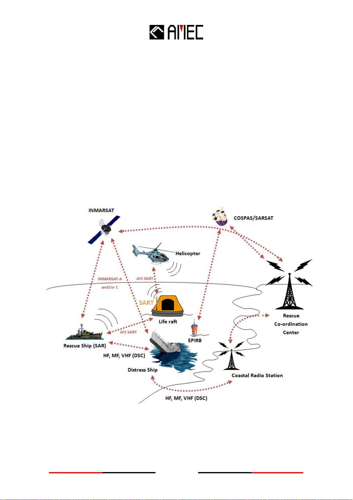
1.1 AIS SART Brief.........................................................................................................................7
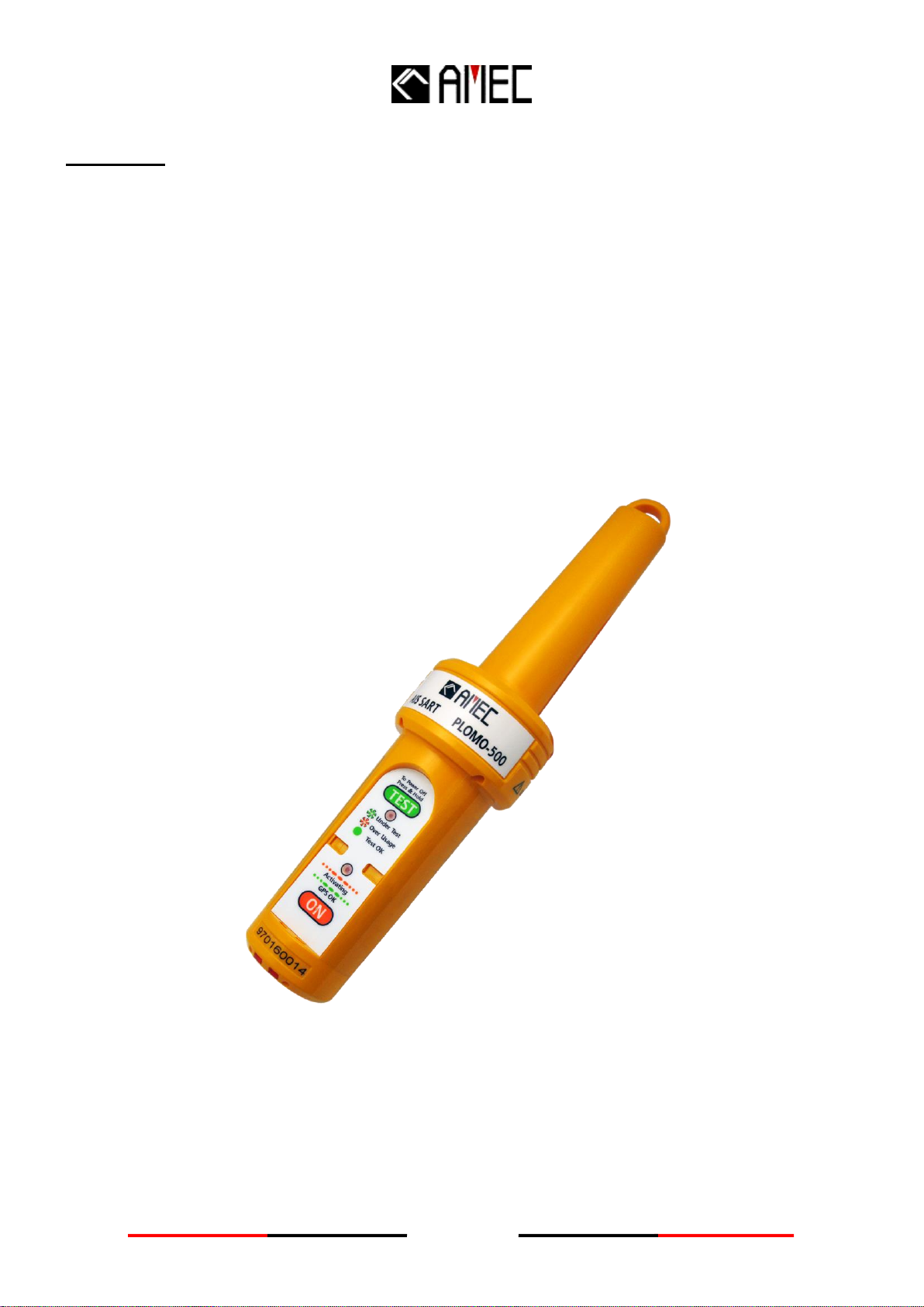
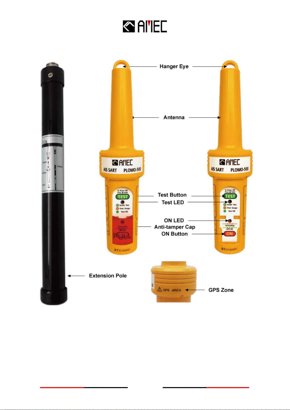
1.2 PLOMO-500 Overview.............................................................................................................8
2 INSTALLATION................................................................................................... 10
2.1 Items in the Package.............................................................................................................10
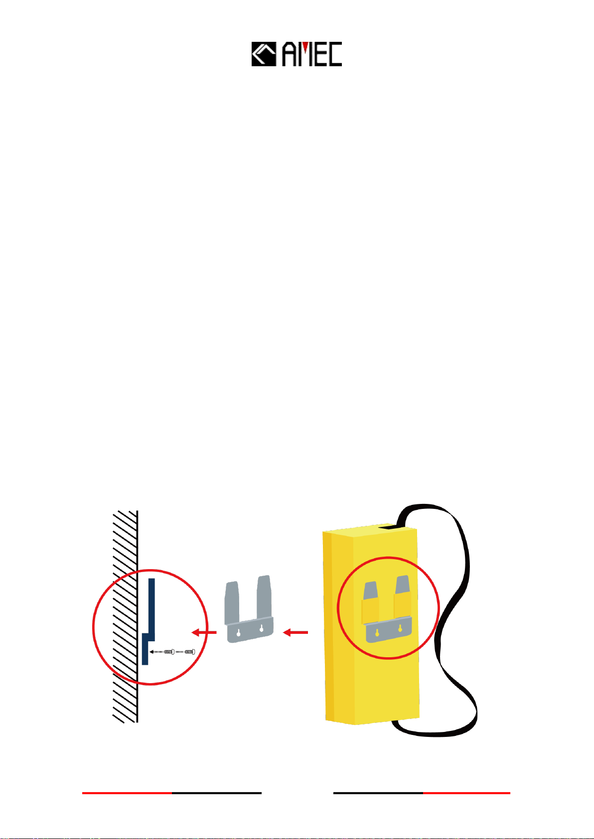
2.2 Wall bracket installation.......................................................................................................11
3 EMERGENCY PROCEDURE............................................................................. 12
3.1 Abandon ship!........................................................................................................................12
3.2 Activation Process ...............................................................................................................13
3.3 Deployment guidelines........................................................................................................14
3.4 Mounting outside a canopy life raft .................................................................................15
3.5 Mounting inside a canopy life raft.....................................................................................15
3.6 Deactivation Process............................................................................................................16
4 AIS SART TARGET VISUALIZATION............................................................. 17
5.1 Servicing schedule................................................................................................................18
5.2 Self-test & inspection ............................................................................................................18
5.3 Self-test procedure.................................................................................................................18
5.4 Mechanical inspection .........................................................................................................20
5.5 Anti-tamper Cap replacement ............................................................................................20
5.6 Battery replacement..............................................................................................................20
5.7 Transportation........................................................................................................................21
5.8 GMDSS inspections..............................................................................................................21
6 APPENDIX........................................................................................................... 22
6.1 Product Specifications............................................................................................................22
6.2 Dimensions ................................................................................................................................24
7 AMEC WORLDWIDE WARRANTY ................................................................... 26
8 DECLARATION OF CONFORMITY .................................................................. 28

7
1 AMEC AIS SART PLOMO-500 Introduction
1.1 AIS SART Brief
AMEC’s PLOMO-500 AIS SART is a self-contained radio transmitter used to locate a survival
craft or distressed vessel by sending updated position reports using Automatic Identification
System (AIS) class-A position report. Primary intended for use in a life raft or survival craft, an
AIS SART can be deployed on board or in the water. GMDSS vessels from 300 to 500 GRT are
required to carry one SART, and vessels over 500 GRT are required to carry two and since
2010.
AIS-SARTs have been a permissible alternative to radar SARTs under SOLAS regulations,
however technically more superior over radar SART thanks to its accurate GPS positioning. The
radar SART would appear only as a series of RADAR returns on the ships radar display leading
to the SARTs location.
Figure 1 SART in Global Maritime Distress Safety System (GMDSS)

8
1.2 PLOMO-500 Overview
Only remove the RED anti-tamper Cap if you intend to operate the AIS SART in a real
emergency. An AIS SART is a single use device, once activated and before returning it to
storage a maintenance service battery replacement will be required.
The AIS SART is packed inside a buoyant carry bag with carry strap. The carry bag contains the
AIS SART main unit, a 1-meter telescopic extension pole and 10 meters buoyant lanyard. The
carry bag may be wall mounted using the wall-mount bracket provided.
The carry bag offers additional protection to the AIS SART both for storage and when carrying
on to a survival craft. Once assembled and ready for deployment the main unit remains buoyant,
waterproof and is tested to survive a 20m drop in to water without damage.
Figure 2 Carry bag of PLOMO-500
The control panel has florescent backlighting that increases its visibility in reduced lighting
conditions. The ON button is protected from accidental activation under a single use
anti-tamper cap. Once activated a dual color Red/Orange LED indicator provides real-time
status induction and will flash the Morse Code “SOS” sequence.

9
Figure 3 AIS SART key features description

10
2 INSTALLATION
2.1 Items in the Package
The PLOMO-500 is typically delivered with standard package as shown in Table 2-1. It is also
illustrated in Figure 2-1 (except manual).
Table 2-1 Standard equipment list
No.
Description
Qty
1
AMEC PLOMO-500 AIS SART
1
2
Manual
1
3
Installation
Kit
Carry Bag
1
1M Extension Pole
1
Wall-Mount Bracket
1
10M buoyant lanyard
1
Screw M4x20
4
Figure 4 Standard package
1. PLOMO-500 x1
2. Carry Bag x1
3. 1M Extension Pole
(with bottom cover)
4. Wall-Mount Bracket
5. 10M buoyant lanyard
6. Screw M4x20 (x4)

11
2.2 Wall bracket installation
When selecting a suitable mounting position consider the following points:
1. Ease of access in an emergency, adjacent to the ship’s bridge wing exits ready for easy
access is recommended.
2. Position at least 1m from compass equipment.
3. Environmental protection, chose a protected location away from the extreme effects of the
weather and protected from powerful vessel wash down hoses.
4. Allow clearance above so that theAIS SART can be easily removed from the bulkhead
bracket.
Mounting procedure
Fix the mounting bracket to the ships wall using marine grade stainless steel screws or bolts;
length is dependent upon application. Bolts should be secured with either stainless steel locking
nuts or stainless-steel nuts with stainless steel shake proof washers.
The wall bracket is designed to mount on a flat surface using two fixing points. Two stainless
steel screws 20mm in length are included. Check that the rear side of the mounting surface is
clear and that the fixing screws will not penetrate something they should not. Offer the bracket
into the chosen position and mark through the mounting slots using the bracket as a template.
Drop the AIS SART carry bag rear pockets over the bracket hook section and push the bag
firmly into place.
Figure 5 Wall mounting

12
3 EMERGENCY PROCEDURE
An AIS SART is a piece of life saving equipment. Its sole purpose is to help survivor location during SAR operations.
It must only be used in situations of imminent danger.
3.1 Abandon ship!
Figure 6 Deployment process
Step 1:
Lift Carry Bag out of
bracket on the wall.
Step 2:
Bring Carry Bag and jump
into a Life Boat.
Step 3:
Open Carry Bag and take
AIS SART, Extension
Pole and buoyant lanyard
out
Step 4:
Connect and rotate
extension pole into
PLOMO-500.
Step 5:
Remove the bottom cover
and extend pole up to 1
Meter

13
3.2 Activation Process
1. Pull and break the red Anti-tamper Cap to reveal the
activation panel.
2. Hold the ON Button for 2 seconds:
- The ON LED flashes Orange during GNSS acquisition
- The ON LED flashes Green once the GNSS fix is acquired.
WARNING: DO NOT COVER GNSS AREA WHILE ACTIVE (see Figure 7)
Figure 7 GPS/GNSS AREA Location
NOTE 1: The GNSS receiver is activated (cold start) when ON is depressed and the Orange LED indicator will initially
flash changing to a Green LED indication when a position fix has been resolved.
NOTE 2: The ON LED flashing sequence is the SOS Morse code flashed every 30 seconds.
NOTE 3: The red Anti-tamper Cap breaks once pulled out and cannot be re-installed by the user.

14
3.3 Deployment guidelines
The AIS SART will work best when the top section has an unobstructed view of the sky.
If it is not possible to pick a location with a totally unobstructed view of the sky, do your
best to maximize the sky view. The antenna datum marked on the pole section should
be positioned more than one meter above sea level when the AIS SART is deployed.
Tie the securing lanyard to the survival craft to avoid loss of the AIS SART, activate and
deploy the AIS SART.
Figure 8 deployment
Step 1:
Release buoyant lanyard
secured to top of the AIS
SART
Step 2:
Hang the AIS SART
inside the life raft at a
height of at least 1 meter
above water level
Step 1:
Extend the pole up to 1
meter.
Step 2:
Pass the pole through the
life raft canopy port hole
and securer the pole in
vertical position.
Method 1
Method 2
Tip.
Tie the lanyard cord between the AIS
SART and the survival craft to
prevent its loss.

15
3.4 Mounting outside a canopy life raft
1. Fully extend the telescopic mounting pole:
Remove the rubber cover from the bottom of the mounting pole; allow the pole
sections to drop. Lock each section together by twisting each section.
2. Release the lanyard spool and tether the free end of the lanyard to a securer fixing
point within the survival craft.
3. Insert the AIS SART through the SART deployment port in the survival craft canopy.
Position the bottom of the support pole within the locating pocket. Secure the pole to
the canopy support.
Depending on the type of survival craft, the mounting pole can also be located on the
outboard side of the survival craft at the doorway entrance on the boarding ramp side.
The AIS SART is mounted in the same way except the pole is secured to the buoyancy
support.
3.5 Mounting inside a canopy life raft
The SART should be switched ON and suspended at highest point of the survival craft; by its
top loop using the lanyard provided.
Note: Operating the AIS SART inside a closed Survival Craft or under a canopy may reduce its
performance.
Figure 9 deployment options

16
3.6 Deactivation Process
1. Hold the TEST button for over 3 seconds to initiate power off.
2. Keep holding TEST until the ON LED stops flashing:
The AIS SART is then deactivated.
Figure 10 Deactivation
NOTE: After de-activating, all LEDs shall be off. If any LED is still flashing, press the
TEST button again for more than 3 seconds to de-activate the unit.

17
4 AIS SART TARGET VISUALIZATION
Under active or test mode, the AIS SART will transmit a message with a 9 digit TX ID
number (MMSI) identity in the following format; 97016YYYY
The AIS SARTs GNSS derived position in latitude and longitude and the TX ID will be
display on the vessels navigation display or AIS receiver equipment.
A SELF TEST mode generated message is displayed as “SART TEST”
The live emergency transmission is displayed as “SART ACTIVE”
Figure 11 AIS SART Target Visualization
Some chart plotters may ignore the SART Test message for better integrity of normal AIS
displays. Please check the user manual of your chart plotter / ECDIS to activate the AIS
SART Test mode.

18
5 MAINTENANCE
5.1 Servicing schedule
As an important item of safety equipment, your AIS SART should be checked regularly
according to the following schedule:
Service Interval
1 month
6 months
6 years
Physical check
Physical check and Self-test
Dealer Battery replacement
All servicing should be carried out by an Approved Service Agent. Always call your
nearest Approved Service Agent and talk to their customer service department before
returning equipment. You can find your nearest Approved Service Agent from:
The AMEC Group website: www.alltekmarine.com
Contacting AMEC Group direct
Contacting a distributor of AMEC products
If the AIS SART must be returned, the original packaging should be used if possible.
Check your AIS SART for any damage or wear and tear according to the manufacturer’s
instructions (please refer to www.alltekmarine.com for further details).
5.2 Self-test & inspection
It is recommended to self-test the AIS SART every 6 months; more frequent self-testing can put
unnecessary drain on the battery. When self-testing, a specially coded AIS test transmission is
sent that will be visible to all AIS users in the locality. As a successful self-test result is
dependent on GNSS position acquisition; testing must be carried out in the open and under an
unobstructed sky.
5.3 Self-test procedure
Remove the AIS SART from its carry bag and assemble the top section onto the mounting pole.
It is not necessary to fully extend the mounting pole. Take the AIS SART outside and hold it aloft
under a clear view of the sky; this will then maximize the speed of the GNSS position fix.
1. Hold “TEST”button for over 3 seconds
WARNING:DO NOT COVER GPS AREA WHILE ACTIVE (see Figure 6)

19
2. The indicator will flash Green LED or Orange LED .
NOTE 1 –Normally the green flashing will happen in 2 mins right after the
GPS/GNSS position is fixed. If it happens at the 5th minute, the SART message will
be transmitted automatically, and GPS/GNSS position might not be fixed. Please
move the AIS SART to a new location which has a clear view of the sky.
NOTE 2 –Orange flashing means the AIS SART has been previously activated or
self-tested more than the maximum of 100 times.
Figure 12 Testing of AIS SART
Indicator
Meaning
Green
AIS SART is under testing without over usage warning
Orange
AIS SART is in under testing with over usage warning
1 long Green
AIS SART complete transmission and light-off after long
green color flash automatically. Check your chart
plotter/ECDIS if the SAR messages are received and
whether the messages include valid GPS position.
NOTE 1 –“Over usage” is caused by the following three situations: battery is run
down, unit has been tested over 100 times, unit has been activated before.
When the “Over usage” orange flashing appears, the AIS SART will still complete
the test procedure. However, it’s recommended to have the battery replaced and
the electronic witness reset to ensure that your AIS SART has the battery power
should the beacon requires it.
NOTE 2 –If the green or orange color is flashing over 3 minutes, GPS/GNSS
position may not be acquired. Move the AIS SART to a different location with a
clear view of the sky overhead.

20
5.4 Mechanical inspection
Inspection
It is recommended to physically check AIS SART routinely to verify:
The battery expiry date has not been exceeded.
Evidence of any damage to the main body, Wall mounted bracket, Carry bag, Extension
Pole, Buoyant Lanyard.
Evidence of dirt; to cleanAIS SART only using fresh water then wipe dry.
WARNING –Do not use any chemical liquid on AIS SART or its accessories.
5.5 Anti-tamper Cap replacement
The AIS SART has a Red anti-tamper protection cap that will be broken during activation. An
AIS SART is a single use device, once activated and before returning it to storage a
maintenance service battery replacement will be required.
NOTE –To replace the anti-tamper cap and battery, please contact your local approved
service agent.
5.6 Battery replacement
The battery pack should be replaced every 6 years or when it reaches its expiry date or if the
AIS SART has been activated.
The battery pack expiry date is marked on the AIS SART main body label. The battery expiry
date should be checked regularly.
Lithium batteries have special disposal requirements. Never incinerate a lithium battery. Never
dispose of one at sea. Your approved service agent will be able to deal with battery disposal.
NOTE –It is recommended that battery change should be performed by an authorized
service agent in order that a complete assessment and integrity check can be
performed. To replace a battery pack, please contact your local approved service
agent.

21
5.7 Transportation
This information is given in good faith and is believed to be accurate at the date of preparation.
AMEC makes no warranty, either express or implied, with respect to this information, and
disclaims all liability from reference on it.
Transport Information
Class: Class 9
UN Number: UN3091
UN Description: Lithium Metal Batteries Contained in Equipment
IATA Packing Instruction for Air: 970 Section II
Packing Instruction for Road & Sea:P903 Special Provision 188
For further information, please refer to the Alltek Marine website: www.alltekmarine.com .
5.8 GMDSS inspections
Vessel that are subject to GMDSS regulations can expect regular visits from ship surveyors
enforcing national legislation. They might check the expiry dates and test the AIS SART to
prove that it is operational.
Leisure vessels are not subject to these inspections. However, in some countries, passenger
and fishing vessels are also subject to inspection.
Other manuals for AIS SART PLOMO-500
1
Table of contents
Other AMEC Transmitter manuals