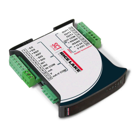
Rice Lake SCT-3300 User manual
Other Rice Lake Transmitter manuals

Rice Lake
Rice Lake 30 Series Administrator Guide
Rice Lake
Rice Lake SCT-1100 User manual
Rice Lake
Rice Lake SCT-1SX-PROFINET User manual
Rice Lake
Rice Lake SCT-1000ETHERNET User manual
Rice Lake
Rice Lake SCT-1SX-MODBUS TCP/IP User manual
Rice Lake
Rice Lake 20 series User manual
Rice Lake
Rice Lake SCT-1SX Series User manual

Rice Lake
Rice Lake SCT-2200 User manual
Rice Lake
Rice Lake Advanced Series User manual

Rice Lake
Rice Lake SCT-1SX Series User manual

Rice Lake
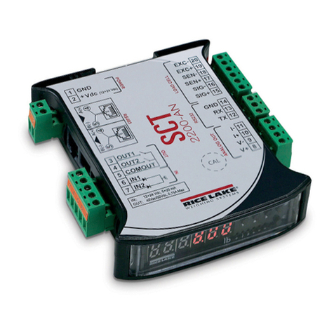
Rice Lake SCT-1SX Series User manual
Rice Lake
Rice Lake SCT-2200 User manual

Rice Lake
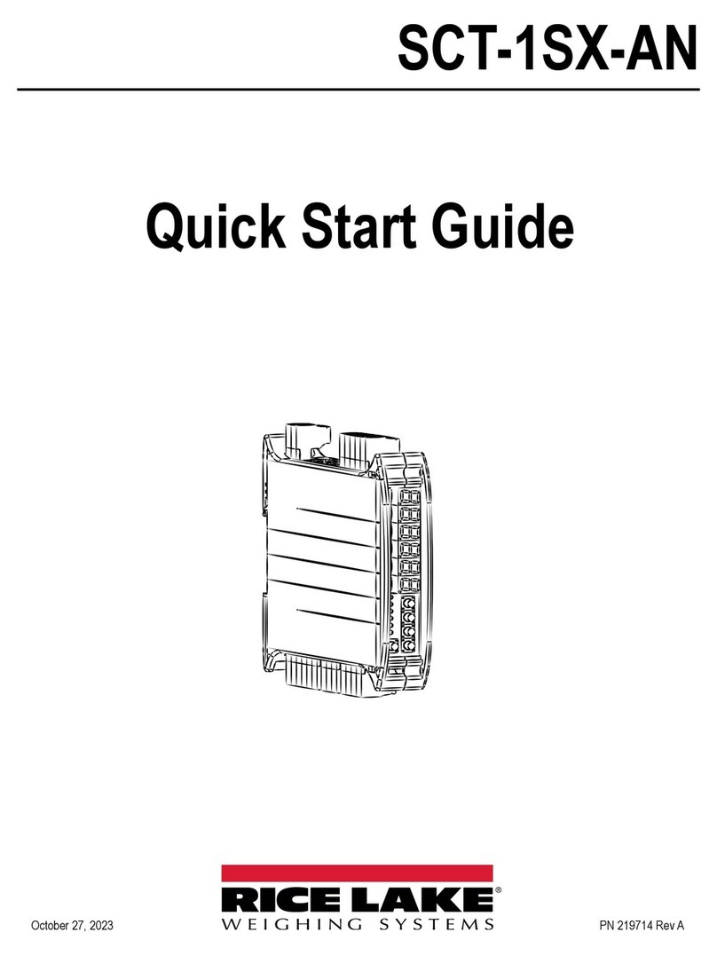
Rice Lake MSI TranSend Series User manual
Rice Lake
Rice Lake SCT-1SX-AN User manual
Rice Lake
Rice Lake SCT20-DN User manual
Rice Lake
Rice Lake SCT-1SX-Ethernet/IP User manual
Rice Lake
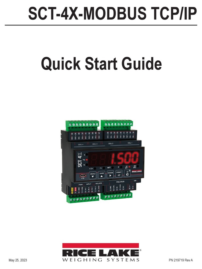
Rice Lake SCT-4X-MODBUS TCP/IP User manual
Rice Lake
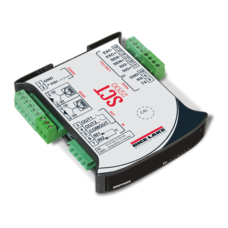
Rice Lake SCT-2200 User manual

Rice Lake
Rice Lake SCT-4X Series User manual

Rice Lake
Rice Lake SCT-4X-AN User manual
Popular Transmitter manuals by other brands

Dejero
Dejero EnGo 3x manual

Rosemount
Rosemount 4600 Reference manual

Speaka Professional
Speaka Professional 2342740 operating instructions

trubomat
trubomat GAB 1000 instruction manual

Teledyne Analytical Instruments
Teledyne Analytical Instruments LXT-380 instructions

Rondish
Rondish UT-11 quick start guide
