Amerec A220FP User manual


The Model A220FP Fragrance Injector Pump is to be used with the AK and 3K steamers when the K200i Freedom
Controlisnotinstalled.Thepumpshouldbemountedinaneasilyaccessiblearea,notmorethan4'abovetheessence
containerandnotmorethan4'belowthesaddlevalve. Theon/offswitchlocatedonthesideofthefragranceinjector
pump must be turned on and remain in the on position.
4211-189 08-09-11
DIAGRAM 1
WARNINGS
The use of fragrance oils may introduce excessive concentration of oil into the steam room, resulting in a health
hazard.
Leavetheroomimmediatelyifyouhaveanyadverseorallergicreactions,includingdifficultybreathingoreye,nasal,
throat or skin irritation, and seek immediate medical attention.
Vapors may cause drowsiness and dizziness. Keep out of the reach of children. In case of contact with eyes, rinse
immediately with plenty of water and seek medical advice. If swallowed, rinse mouth with water (only if person is
conscious)andseek medical advice immediately.
Essential oils may be highly flammable! Keep away from sources of ignition. No smoking! Keep container tightly closed
andin a well ventilatedplace.
Not for use in acrylic or fiberglass rooms.
The pump has been factory set to deliver a suitable amount of aromatic oil into a typical sized steam room. Use
caution when increasing the speed on the pump as this may introduce excessive concentration of oil into the steam
room,resultingin a health hazard.
A220FP Fragrance Injector Pump
Installation and Operating Instructions
AK Steam
Generator
Fragrance
InjectorPump
Saddle Valve (supplied)
Mount on top of Steam Line
Essence Container
(supplied)
Thermal Switch
(supplied)
Mount on top
of Steam Line
120VAC - 24VAC
Power Adapter
Fragrance
Controlller
Clear
Tubing
(supplied)
On/Off
Switch
3'Min.
Installation Overview

4211-189 08-09-11
A220FP Fragrance Injector Pump
Installation and Operating Instructions page 2
DIAGRAM 3
DIAGRAM 2
PiercingArm
Brass Nut
Brass
Sleeve
Plastic
Compression
Fitting
General Installation
Determinelocations suitableformountingtheFragrance system'scomponents:
•TheOn/Offswitchshouldbemountedwhereitisconvenienttotheuser. Itisusedtostartorstopthefragrancecontroller.
The switch may be mounted inside or outside the steam room. A 25' cable is provided to connect the switch to the
Controller.
•Theessencebottleandpumpshouldbelocatedwheretheyareprotectedfromfreezing,easilyaccessibleforcheckingthe
levelofand refillingtheessentialoil,and wherethebottlewillbe nomorethan4'belowthepumpwiththepumpmounted
onaverticalsurface. Donotinstallnearflammableorcorrosivematerialsorchemicals,inareashavinghighconcentrations
ofchlorineornearopenflames. Thirteenfeetof cleartubingisprovidedtoconnectthepumptotheessencebottleandto
the saddle valve. The pump's 9' power cord will connect to the controller.
•Locatethesaddlevalveandthethermalswitchneareachotheronthetopofthesteamoutletpipe,atleast3'fromthesteam
generator (as close to the steam room as possible for best results) and with the saddle valve no more than 4' above the
pump. Theymustbeinaneasilyaccessibleareaandclearlyvisibletoallowservice,suchasmonitoringforleaksorhose
damage. A25'cableisprovidedtoconnectthethermalswitchtothe controller.Note:If3'min.cannotbe met,pleasecall
the factory for assistance at 800-363-0251
•The120VACto24VACpoweradapter should be mounted to a convenient wall outlet. A 25' cable is provided to connect
the adapter to the controller.
•The controller should be mounted on a wall in an easily accessible location convenient to the other components.
• The system should not be installed in areas accessible to children.
A LOCKED ROOM IS STRONGLY RECOMMENDED (i.e. a utility room).
Install the Saddle Valve (Diagrams 2 and 3)
Thesteamlinemustslopeawayfromthesaddlevalvetowards
the steam room to prevent essence from draining back into
thesteamtank.If allowed to drain backintothesteam tank,
some oils can cause erratic steamer operation and may
damagetheheatingelements.
Thesaddlevalve(supplied)shouldbemountedontopofthe
1/2" copper steamline as far away from the generator as
possible(3'minimum).
•Slidethebrassnutontothepump'scleartransfer-outtubing
followed by the plastic compression fitting.
• Insert the brass sleeve inside the transfer-out hose.
• Tighten the brass nut.
•Tightenthepiercing arm all the way downthroughthe
1/2 inch copper steam line and then all the way back out.
Install the Thermal Switch (Diagram 3)
The thermal switch should be mounted on top of the steam
linenear thesaddlevalve. The thermalswitchensures that
oil is added only while steam is being sent to the room.
•Usethe provided hose clamptosecurethe thermal switch
to the pipe as shown in diagram 3. Tighten the clamp only
enoughtosecuretheswitchtothepipe-donotovertighten!
•Connecttheswitch'swirestotwoofthewiresintheprovided
cable and connect the other end of those wires to the
fragrance controller's terminal block's SWITCH terminals.
Thermal
Switch
Hose
Clamp
ClearTransfer-outTubing

4211-189 08-09-11
page 3
A220FP Fragrance Injector Pump
Installation and Operating Instructions
Install the Pump with the Provided Bracket
Select a location to mount the pump and essence con-
tainer.Thepumpshould bemounted ona verticalsurface
such as a wall, no more than 4' above the essence con-
tainerandnomorethan4'belowthesaddlevalve.
• Mount the plastic bracket with the provided screw
(see Diagram 4)
• In case of tiled or low friction walls, also use the supplied
adhesive tape. Peel off one of the two protective foils
from the tape, stick the tape to the bracket, peel off the
second protective foil and press the bracket in place on
the wall, then proceed to mount the bracket with the
providedscrew
• Slide the grooves on the pump over the bracket.
• Press the top of the pump's On/Off/Mom switch to turn
the pump off.
Install Essence Oil Bottle and Caddy
•Unscrew thebottlecap andremovethe swivel coverto
expose 1/4"“ hole in cap (Diagram 5).
• Insert clear tubing through the hole in the cap.
• Insert the end of the tubing into the metal weight so that it
exits from the flared end of the weight.
• Insert the filter’s barbed fitting into the end of the tubing.
• Tighten the tubing by sliding the weight over the barb until
it is flush with the filter.
• It is strongly recommended to use the suction filter in all
situations. Make sure that it reaches the bottom of the
essence bottle. It should be cleaned periodically to re-
move any product residue. (Diagram 6 shows the suction
filter installation.)
• Drop the tubing, with weight and filter attached, through
the bottle opening and allow the filter body to reach the
bottom of the essence bottle (Diagram 7).
• Screw the cap on the bottle, leaving the cap loose
enough to allow for ventilation.
• Mount the bottle caddy to a vertical surface with two (2)
screwsprovided(Diagram7),belowandpreferrablynear
the pump but not more than 4' below.
• Set bottle in caddy.
Install the Pump Tubing
The pump has two tubing connections at the bottom of the
front side. The left connection is the inlet, where the
essence oil enters from the bottle's suction tube. The right
connection is the outlet, where the transfer tube carries oil
tothesaddle valve. The inletismarked on the clearcover
with a and the outlet is marked with a .
Forproper pump operation, the pump must be no more
than 4' above the bottom of the essence bottle and no
morethan4'belowthesaddlevalve.
DIAGRAM5
DIAGRAM4
DIAGRAM6
Adhesive
Tape
Bracket
Screw
Pump Back
Metallic Filter
Ballast
SuctionTube
Mounting
Direction
Filter Body
IMPORTANT: Leave the cap loose
enough to allow for ventilation.
DIAGRAM7
Caddy
On/Off/Momswitch
Bracket
Mount

4211-189 08-09-11
A220FP Fragrance Injector Pump
Installation and Operating Instructions page 4
DIAGRAM9
Pump Front
Inlet Outlet
PowerCord
TransferOutTube
SuctionTube
Install the Pump Tubing (Diagram 8)
• Route the suction tubing from the essence bottle to the
pump making sure there are no kinks in the tubing and
that the tubing is protected from sharp edges, heat or
other conditions which could damage it. Lightly secure
the tubing in place as needed for protection.
• Unscrew inlet nut from pump.
• Insert open end of suction tube from the bottle through
the hole of the inlet's nut and firmly push the tube end
onto the cone of the pump's inlet fitting.
• Screw the inlet's nut onto the suction fitting.
**(Hand tighten only)**
• Repeat these steps for the outlet's transfer out tube
connection to the saddle valve. Keep the tubing away
from contact with the steam pipe.
Wire the Power Adapter (Diagram 9)
Thepoweradapterconverts120VACfromawalloutletto
the24VACneededforthepumpandcontrolleroperation.
Strip both ends of two wires in the 25' cable provided 1/4" to
3/8" and connect one end to the screw terminals on the
poweradapter.
Prime the Pump
The tubing must be filled with essence oil all the way to the
saddlevalvebeforefragranceisaddedtothesteam. Todo
this quickly,
• Fill the essence bottle with fragrance oil.
• Connect the power cord from the pump to the wires from
the power adapter.
• Plug the adapter into a convenient wall outlet.
• Set the Pump's switch (Diagram 4) to ON and the pump
should start.
• Run the pump until the oil has filled the tube from the
bottle just to the saddle valve. There should be few, if
any, air bubbles. Do not empty the essence bottle!
• Disconnect the power adapter from the pump wires.
Alternatively,aftercompletingtheinstallation,runthe
Fragrance Control until the tubing is filled with oil. This
may take a few cycles. See OPERATING INSTRUCTIONS.
Install the Fragrance Controller (Diagrams 10 & 11)
Thepump'selectricalpowercomesfromthefragrance
controller. Thecontrollershould be mounted on awall
withinreach ofthepump's 9'power cord.
•Remove thecontroller'sfront cover bypullingout slightly
on the sides to unsnap it. Mount the controller to the wall
using two screws through the mounting holes in the
controller's base.
• Run the power adapter's cable to the controller and
through the first hole in the controller's end. Insert the
stripped wire endsinto the terminal block's 24VAC positions
SpeedRegulator
DIAGRAM8
Wires from
PowerAdapter Cableto
On/OffSwitch
PowerCablefromPump CabletoThermalSwitch
Mounting
Screws
DIAGRAM11
DIAGRAM10

4211-189 08-09-11
page 5
A220FP Fragrance Injector Pump
Installation and Operating Instructions
2 GANG ROUGH-IN BOX
DIAGRAM 14
DIAGRAM 13
APPLYSEALANT
(100% SILICONE CAULK)
TILE UP TO
45 mm DIAMETER HOLE
IN FINISHED WALL
(OPTIONAL NUT IF BACK OF
WALLIS ACCESSABLE)
DIAGRAM13
DIAGRAM12
SinglePosition
Rough-inBox
(optional)
ApplySealant
(100%Silicone
Caulk)
Tileup to 1-3/4"
diameterholein
finishedwall
Install the Fragrance Controller (continued)
while pressing the terminal block tabs with a small tip
screw driver. Release the tabs to secure the wires.
•Place a strain relief(provided,notshown) around the
cable Close to the controller's end and squeeze it closed
with pliers while pushing it into the hole to secure the
cable.
• Plug the adapter into a convenient wall outlet.
• Secure the cord to the wall as needed to prevent stress or
other risks of damage.
•Runthepump's power cord to the controller and through
the second hole in the controller's end. Connect the cord
to the terminals block's PUMP positions and install a
strain relief and secure the cord in the same manner used
for the power cable.
•Run the thermal switch's cable to the controller and
through the third hole in the controller's end. Connect the
stripped wires ends to the terminals block's SWITCH
positions, install a strain relief and secure the cable in
the same manner used for the power cable.
Install the On/Off Switch (Diagrams 12 & 13)
Thelowvoltagecontrolcanbemounteddirectlytoa
finished wall either inside or outside the steam room.
• Rough-in the control cable (this cable has an plug on
each end similar to a telephone's).
• Using a 1-3/4" hole saw, drill a hole in the finished wall
where the control is to be mounted.
• Locate the control cable, pull it out through the 1-3/4" hole
and plug the cable into the connector in the back of the
control housing.
• Run a bead of 100% silicone caulk around the perimeter
on the back of the control housing. Insert the control into
the 1-3/4" hole.
• Using the methods previously listed, connect the other
end of the control cable to the Fragrance Controller's
CONTROL jack and secure the cable..
OPERATINGINSTRUCTIONS
Initial Set-Up
• Make sure the essence bottle is filled with fragrance oil. * Note: Never let the essence container or tubing run dry.
An extended lack of oil could cause damage to the tubing or pump.
• Make sure the power adapter is connected to 120VAC then turn the pump on by pressing the pump's On/Off/Mom
switch in to the center ON position. Note: the pump will not run until the Fragrance Controller is turned on by the
On/Off switch and steam is enterring the room.
BasicOperation
To turn on the injector system, simply press the switch on the On/Off switch. Once pressed:
• The switch's LED will light, indicating that the injector system is running.
• The pump will run for a short time every 2 minutes, if the steam is heating the room.
• After about 15 minutes, the system will automatically turn off and the switchs LED will turn off.
Note: Fragrance will not be injected until the room is over 100° F.

4211-189 08-09-11
A220FP Fragrance Injector Pump
Installation and Operating Instructions page 6
BasicOperation(continued)
• Pressing the switch while the injector system is running will turn the system off again.
• The essential oil will only be pumped into the steam outlet while steam is being sent to the room. This helps carry the
essence into the room and reduces the risk of oil building up in the steam line, unused.
• Repeatedly turning the injector system on and off will not affect the amount of essence released to the room.
We recommend starting the Fragrance Injector after starting your steam bath. Start at about 10 minutes after the steamer
is turned on then adjust this period with later baths until you have determined how long gives you the right amount of
essence in your room. Starting the injector too early can cause the room to have too much essence.
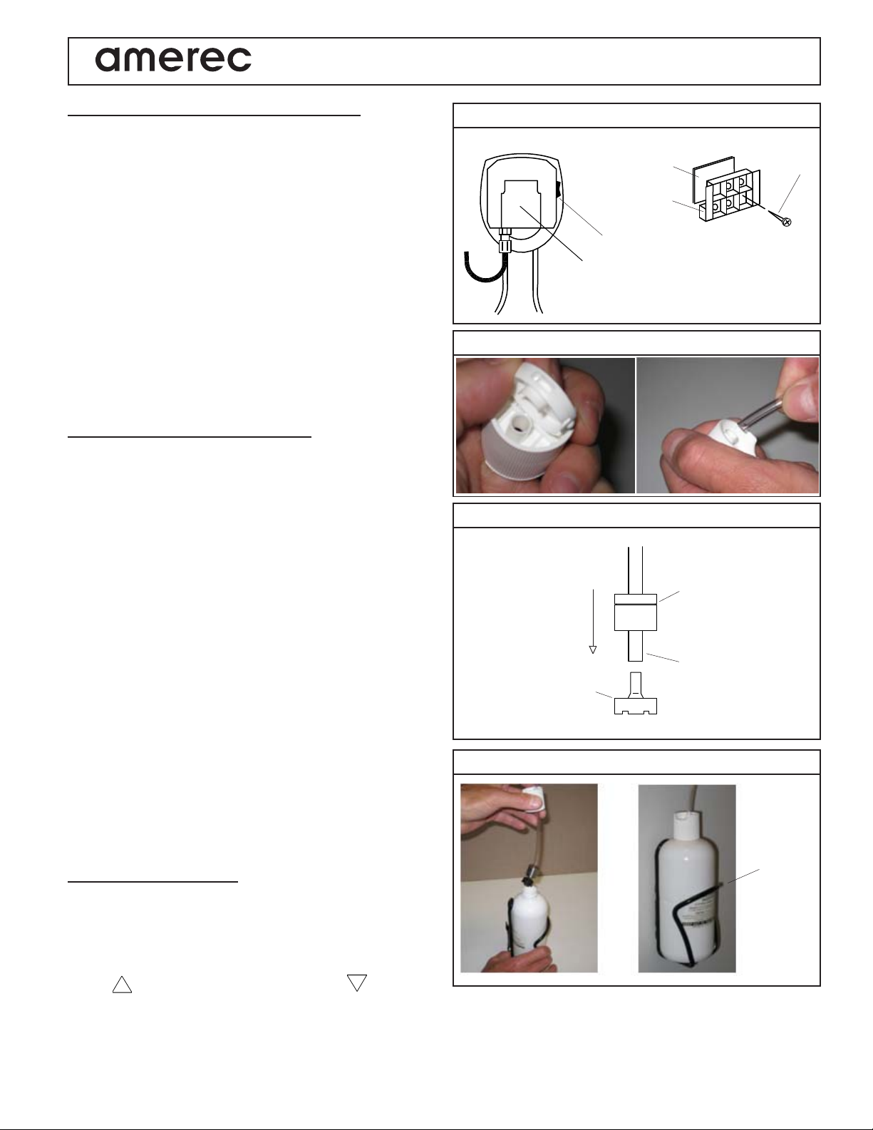
Speed (Flow Rate) Adjustment (Diagram 8)
You can adjust how much essence oil is added to your bath by changing the pump's speed. The speed is set at the
factory at the medium level and the injector should be tested for user preference at this speed first.
Toadjustthespeedremovetheclearcover on the front of the pump. The speed adjustment may be found to the right of
the pump's LED. Make only small adjustments and retest after each adjustment until the preferred speed is determined.
• To reduce speed, use a small screwdriver to turn the speed adjustment screw to the left (counterclockwise).
• To increase speed, use a small screwdriver to turn the speed adjustment screw to the right (clockwise).
Whenfinished,replacetheclear cover. Lightly tighten the cover's mounting screws - Do not over tighten!Thecovermay
be damaged if its screws are tightened too much!
Trouble Shooting
• If there is no essence being supplied,
Make sure the pump is operating correctly.
Make sure the essence bottle is full and the filter is clean and in the essence oil.
Make sure the pump tubing is filled with essence oil.
Check the pump's squeeze tube for damage or leaks.
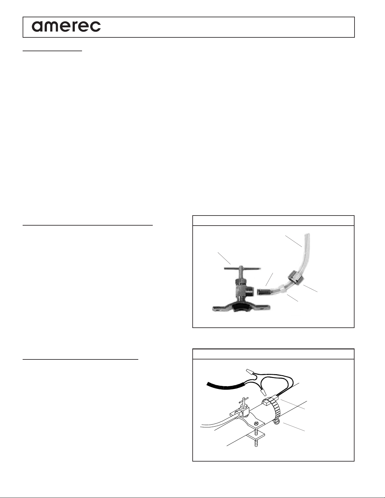
• If the essence supply into the steam line becomes clogged, tighten the piercing arm (see Diagram 2) all the way down
through the 1/2 inch copper steam line and then all the way back out.
• If the essence scent is too strong and the pump is set at it's lowest setting, the essence can be diluted with 100%
safflower oil available at most grocery stores.
• If the On/Off switch's LED does not light, press the pump's switch to its Mom position: the pump should turn and its
LED should light. If the pump is working, there may be a fault with the ON/Off control or its cable. Check its connec-
tions and call Steam Service if the fault is not found.
• If the pump does not turn and the LEDs light, the pump may be faulty; call Steam Service.
• If the pump and LEDs do not work, make sure the wiring connections are correct and that the power adapter is
connected to a working 120VAC outlet. A voltmeter may be used to check the transformer output: it should be 24VAC.
Fortroubleshootingassistance,contactTechnicalSupportat1-800-363-0251
Pump Squeeze Tube Replacement
Toremovethesqueezetube:
•Unplugthepoweradapter.
•Removethetransparentfrontcover.
• Turn the roller assembly so that the rollers are situated vertically, slide the connection on the left toward you pulling the
tube out of its seat and manually rotate the roller assembly clockwise until it is possible to extract the right hand side
connection from its seat.
To install the new tube:
• Turn the roller assembly so that the rollers are lined up horizontally;
• Insert the connection in its seat on the left of the pump with the curved side towards the rear of the pump and
push the tube into its seat while manually rotating the roller housing clockwise until it is possible to
insert the right hand side connection into its seat.
• Remount the front cover. Tighten the cover's screw until snug. Do not over tighten! The cover may be damaged if its
screws are tightened too much!

4211-189 08-09-11
page 7
A220FP Fragrance Injector Pump
Installation and Operating Instructions
17
16
13
12
9
1
1
2
3
4
5
6
7
8
9
10
11
12
13
14
15
16
17
18
19
Provided
1
1
2
1
1
1
1
1
1
*
*
*
*
1
1
1
1
2
1
*
Part #
8855-140
5304-031
5331-12
4211-136
4000-23
4980-03
9140-101
3174-01
5332-04
*
*
5011-05
*
9253-173
8221-03
2064-720
3119-08
2191-05
1301-15
*
Description
FragranceController
Cable,ModularPlugs,8Conductor,25'
Cable,3Conductor,25'
Instructions,RoughIn
RoughInBracket
RoughInInsert
On/OffControl
FragrancePump,WithTubing
PowerAdapter,120VACto24VAC
WallMounting Bracket and Tape
Tubing,12'
SqueezeTube,Replacement
Filter and Weight
Essential Oil, Eucalyptus, 16 oz
BottleCage
SaddleValve
ThermalSwitch
WireNut
HoseClamp, WormDrive,#8, 1/2-1",Stainless
Part of Fragrace Pump kit. Contact Steam
Serviceforadditionalorreplacementparts.
Item
10
8
14
For assistance, contact Technical Support at 1-800-363-0251
P.O. Box 2258, Woodinville, WA 98072
800-363-0251 Fax: 425-951-1130
Table of contents
Other Amerec Plumbing Product manuals
Popular Plumbing Product manuals by other brands

CIFIAL
CIFIAL 3215005 Assembly and instruction manual

KWC
KWC ANIMA ANMX502 Installation and operating instructions

MAINLINE
MAINLINE Elite Treme TR137 installation instructions

Hans Grohe
Hans Grohe Axor Carlton 17133 1 Series Installation/Warranty

Reece
Reece Milli Series quick start guide

Hans Grohe
Hans Grohe Ecostat 1001 SL 13287000 Instructions for use/assembly instructions

Spectrum Brands
Spectrum Brands Pfister Bronson R89-XBS Quick installation guide

Waterstone
Waterstone AG231-1 Installation

Everpure
Everpure Designer Series EV9000-86 Specification sheet

Moen
Moen WS84004 Series installation guide

DAELIM
DAELIM FB6600 Installation and operation manual

Moen
Moen L2351 Series installation instructions