manuals.online logo
Brands
  1. Home
  2. •
  3. Brands
  4. •
  5. American Audio
  6. •
  7. Amplifier
  8. •
  9. American Audio GX-300 User manual

American Audio GX-300 User manual

User Instructions
American Audio®
American Audio®
4295 Charter Street
Los Angeles Ca. 90058
Revised 5/01
GX-300
Professional Power Amplifier
Power
ON
American Audio™
Professional Stereo Amplifier
Power Bridge Stereo Clip Signal Clip Signal
Min Max Min Max
GX-300
Ch A Ch B
CONTENTS
QUICK START....................................................................................................................................................................2
SAFETY PRECAUTION....................................................................................................................................................3
FRONT PANEL............................................................................................................................................................5
REAR PANEL..............................................................................................................................................................6
INPUTS........................................................................................................................................................................7
OUTPUTS....................................................................................................................................................................8
LOW-CUT FILTER......................................................................................................................................................11
RESET BREAKER.........................................................................................................................................................11
STEREO/BRIDGED MONO........................................................................................................................................11
PROTECTION............................................................................................................................................................11
SPECIFICATIONS.......................................................................................................................................................12
Quick Start: The following instructions are provide as a guide for
those user already familiar with the basic operation of amplifiers.
1. Be sure you amplifier and all other audio equipment is power
down before attempting any type of connection. The amplifier
power button is located on the lower left-hand side of the front of
amplifier.
2. Securely mount the amplifier in standard 19" rack, or position it
on a solid surface.
3. Connect the left and right output signal a mixer, preamp, or pro-
cessor to the amplifiers inputs. Use either balanced/unbalanced
1/4" (6.35 mm) phono jacks, 3-pin balanced XLR jacks, or unbal-
anced RCA jacks on the rear of amplifier. At this point chose the run
the amplifier in BRIDGE or STEREO mode. (Stereo is the default
setting, see page 5.)
4. Connect the left and right speakers to the amplifiers output ter-
minals. Use either the 1/4" (6.35 mm) jacks or the 3-way banana
binding post.
WARNING: The red banana output terminals on the rear of the
unit marked with the symbol are dangerous when active. Exter-
nal wiring connected to these terminals requires installation by a
qualified person, or make use of preconstructed speaker cables
available at a local professional sound retailer.
5. Connect the amplifier to a power outlet with a matching power
supply.
6. Turn on all audio components except the amplifier. Be sure both
Channel A and Channel B volume controls are turned all the way
down (full counter-clockwise), and turn on main power.
7. Turn the mixer or other audio components up and adjust the
amplifier levels. The green signal LED's on the face of the unit will
indicate signal is being received.
GX-300™ Power Amplifier Instructions page 2
FOR OPTIMUM PERFORMANCE AND
RELIABILITY DO NOT PRESENT THE
AMPLIFIER WITH A SPEAKER LOAD
OF LESS THAN 2 OHMS. OR ANY
COMBINATION OF SPEAKERS THAT
TOGETHER ARE LESS THAN 2
OHMS!
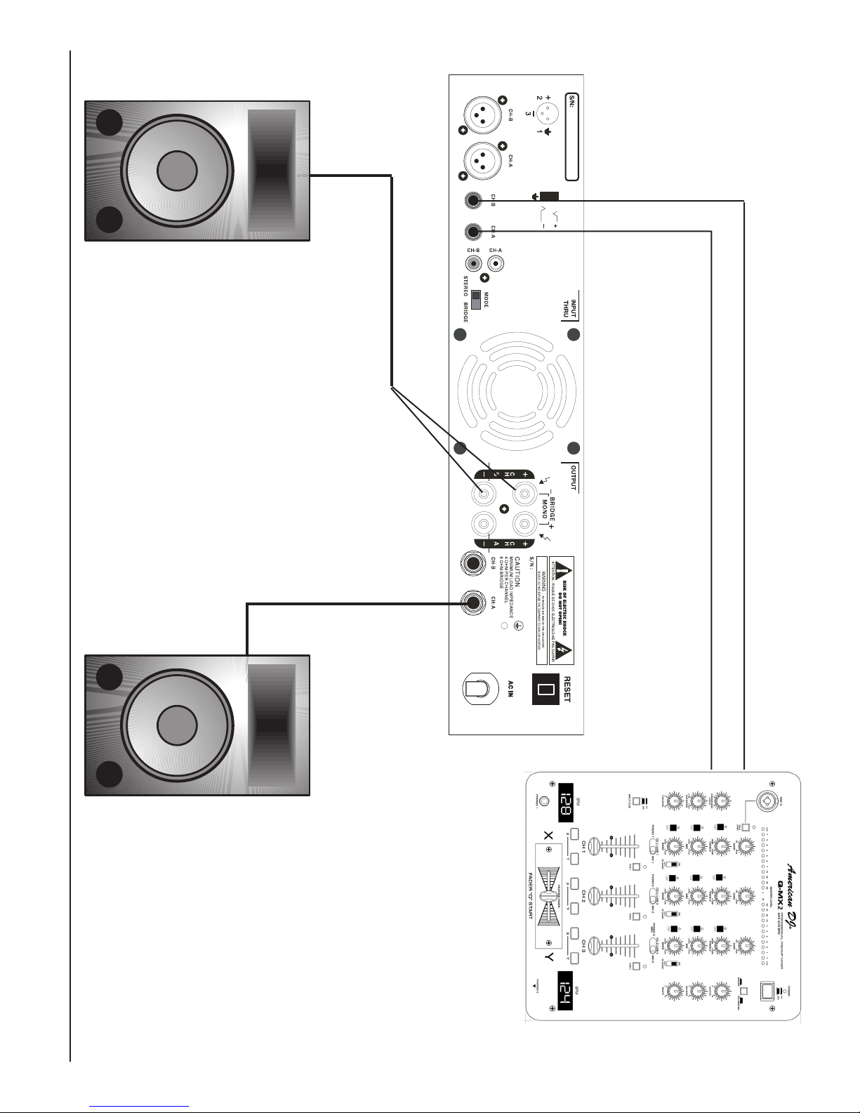
USING ONE SPEAKER, IT MUST BE
RATED AT 4 OR MORE OHMS.
USING TWO SPEAKERS, THEY MUST
RATED EACH AT 4 OR MORE OHMS.
USING THREE SPEAKERS, THEY
MUST BE RATED EACH AT 8 OR
MORE OHMS.
GX-300™ Power Amplifier Instructions page 3
CAUTION: TO REDUCE THE RISK OF ELECTRIC
SHOCK, DO NOT REMOVE THE COVER.
THERE ARE NO USER SERVICEABLE PARTS
INSIDE. REFER ALL SERVICE TO YOUR
AUTHORIZED AMERICAN AUDIO®DEALER.
The lightning flash with an arrow triangular
symbol is intended to alert the user to the
presence of non insulated “dangerous volt-
age” within the products enclosure, and
may be of sufficient magnitude to constitute
a risk of electric shock.
The exclamation point triangular symbol is
intended to alert the user to the presence
of important operating and maintenance
(servicing) instructions in the user manual
accompanying the CD player.
CAUTION
Do not open -
Risk of electric shock POUR ASSURER LA FIABILETE ET
OBTENIT UNE PERFORMANCE OPTIMALE,
NESOUMETTE JAMAIS L’AMPLIFICATEUR
A UNE CHARGE D’IMPEDANCE TOTALE
INFERIEURE A 2 OHMS, NI AVEC UN H.P.
NI EN COMBINAISON DES H.P.
AVEC UN H.P., IL FAUT UNE CHARGE
D’IMPEDANCE MINIMUM DE 2 OHMS.
AVEC DEUX H.P., FAUT POUR CHAOUN
UNE CHARGE D’IMPEDANCE MINIMUM
DE 4 OHMS.
AVEC TROIS H.P., FAU T P O UR CHAOUN
UNE CHURGE D’IMPEDANCE MINIMUM
DE 8 OHMS.
1. Be sure to save the packing carton in the unlikely event this
unit may have to be return the unit for service.
2. Read all documentation before attempting to operate your
new amplifier. Please save all you documentation for future
reference.
3. To reduce the risk of fire or electrical shock, do expose this unit
to rain, moisture, water or other liquids.
4. Be sure that the local power outlet match that or the required
voltage for your amplifier.
5. Do not attempt to operate this unit if the power cord has been
frayed or broken. Please route your power cord out of the way
of foot traffic.
6. Do not attempt to remove or break off the ground prong
from the electrical cord. This prong is used to reduce the
risk of electrical shock and fire in case of an internal short.
7. Always have the front gain controls set to their lowest level
during initial power-up to prevent speaker damage .
8. Disconnect from main power before making any type of
connection.
9. Do not block the units cooling vents or fan intake. If this unit is
being used in an extremely dusty or smoky environment, the
unit should be blown through on a regular basis.
10.Do not remove the top cover under any conditions. There are
no user serviceable parts inside.
11.Do not drive the inputs with a signal level greater than that
required to drive equipment to full output.
12.Do not try to run the input signal of an amplifier by the
output of any other amplifier.
13.Never ground a RED (positive) terminal.
14.Disconnect the unit’s main power when left unused for long
periods of time.
Important Precautions
General Information
Introduction: Congratulations and thank you for purchasing the
American Audio® GX-300™ amplifier. This amplifier is a represen-
tation of American Audio’s continuing commitment to produce the
best and highest quality products at an affordable price. Please
read and understand this manual completely before attempting
to operate your new amplifier. This booklet contains important
information concerning the proper any safe operation of your new
amplifier.
Unpacking: Carefully open and unpack your amplifier. After
unpacking, inspect the amplifier for any type of damage that may
have occurred during shipping or transit. If you notice any type of
damage notify your dealer immediately for instructions.
Installation: This amplifier is designed to mount in a standard
19” rack. The front panel provides four holes used to screw the
unit into a rack.
Cart Installation: Use only with a stable cart or
stand. When a cart is used, use caution when moving
the cart/unit combination to avoid injury from tip-overs.
Customer Support: For assistance beyond that which is cover
in this manual, American Audio®provides a toll free customer
support line, to provide additional set up help and to answer
any question should you encounter problems during your set
up or initial operation. For service related issue please contact
American Audio®Technical Support Team. Service Hours are
Monday through Friday 9:00 a.m. to 5:00 p.m. Pacific Standard
Time.
Voice: (800) 322-6337
Fax: (323) 582-2610
E-mail: [email protected]
You may also visit us on the web at www.americandj.com for any
comments or suggestions.
GX-300™ Power Amplifier Instructions page 4
Features
1. Bridge-Mono/Stereo mode switch. This switch allow the ampli-
fier operating mode to toggle between stereo and bride-mono
mode.
2. Built-in protection circuitry: DC output protection, Overload
protection (clip limiting), and Short circuit protection.
3. Variable speed cooling fan for optimal performance and cool-
ing.
4. 19" (48.3 cm) rackmountable case design.
5. 9" (220 cm) shallow case design, allowing this amp to be
installed in a shallow rack, stacked on top of each other, or
stacked on a cart.
6. Three different input options; 1/4" balanced/unbalanced jacks,
balanced XLR jacks, and Unbalanced RCA jacks.
7. Two different output options (speaker connections); 1/4" jacks
or 3-way banana style binding post.
8. Dedented channel gain controls on the front panel.
9. Rear panel 5 amp reset button (breaker type).
10. Two year limited warranty.
11. Light weight only 16 Lbs (4.1 Kgs)
12. Two rackspace case design.
13. Mode monitor LED's on the front panel detail Bride-Mono or
Stereo Operation.
14. Signal and Clip LED indicators on the front panel detail input
signal integrity.
15. Front panel power switch and power LED indicator.
FRONT PANEL
1. POWER BUTTON -
This is used to activate the amplifier's main power. When main
power is activated it will indicated the Power LED (2).
2. POWER LED -
This green LED will glow when the amplifier is turned on, indicat-
ing main power is traveling through the unit.
3. BRIDGE LED -
This green LED will glow when the amplifier is in Mono-Bridge
mode. For more information on operating in Mono-Bridge mode
see page .
4. STEREO LED -
This green LED will glow when the amplifier is in Stereo mode.
For more information on operating in Stereo mode see page .
5. CHANNEL A CLIP INDICATOR -
This red LED will glow begin to flash at the amplifiers clipping
point, the point when the output signal begins to distort. Under
heavy clipping lower the input gains (Diagram 8) to reduce the risk
of damage to your speakers and amplifier. This LED will also glow
constantly when channel A goes in to protect mode. In protect
GX-300™ Power Amplifier Instructions page 5
mode the output signal to the speakers will terminated.
6. CHANNEL A SIGNAL INDICATOR -
This Green LED will glow when there is an input signal present.
7. CHANNEL A GAIN CONTROL -
This knob adjust the channel one volume output to the speakers
connect to channel one.
8. CHANNEL B CLIP INDICATOR -
This LED comes on at the amplifiers clipping point, the point when
the output signal begins to distort. Under heavy clipping lower the
input gains (Diagram 10) to reduce the risk of damage to your
speakers and amplifier. This LED will also glow constantly when
channel B goes in to protect mode. In protect mode the output
signal to the speakers will terminated.
9. CHANNEL B SIGNAL INDICATOR -
This Green LED will glow when there is an input signal present.
10. CHANNEL B GAIN CONTROL -
This knob adjust the channel one volume output to the speakers
connect to channel one.
Diagram 1
Power
ON
American Audio™
Professional Stereo Amplifier
Power Bridge Stereo Clip Signal Clip Signal
Min Max Min Max
GX-300
Ch A Ch B
16891075432
REAR PANEL
11. Channel B XLR Input -
Connect a mixer's balanced channel "B" or channel two output
signal to this balanced XLR input jack. Pin two is negative, Pin
one is ground, Pin three is ground.
12. Channel A XLR Input -
Connect a mixer's balanced channel "A" or channel one output
signal to this balanced XLR input jack. Pin two is negative, Pin
one is ground, Pin three is ground.
13. Channel B 1/4" Input -
This jack is a balanced or unbalanced 1/4" phono plug input jack.
Connect a mixer's channel "B" or channel two output signal to this
input jack. Tip is positive.
14. Channel A 1/4" Input -
This jack is a balanced or unbalanced 1/4" phono plug input jack.
Connect a mixer's channel "A" or channel one output signal to this
input jack. Tip is positive.
15. Unbalanced RCA Input -
These jacks are standard unbalanced RCA input jacks. The right
channel jack is indicated with red and left is indicated with white.
16. Bridge-Mono/Stereo MODE Switch -
This switch changes the amplifier operating mode from stereo to
bridge-mono. The amplifier's default operating mode is stereo.
17. COOLING FAN -
This is a variable speed cooling fan. Never block the fan in any
way or mount in an enclose rack, doing so may cause the ampli-
fier to overheat and fail.
18. Channel 2 Speaker Output/3 Way Binding Post -
Connect your channel two speakers to channel two output.
19. Channel 1 Speaker Output/3 Way Binding Post -
Connect your channel one speakers to channel one output.
20. Channel 2 1/4" Speaker Output -
Connect your channel two speakers to channel two output.
21. Channel 1 1/4" Speaker Output -
Connect your channel one speakers to channel one output.
22. RESET BREAKER -
This is a 5 amp breaker, that will clip when ever the unit exceeds
the maximum of power drawl.
23. A/C Power Input -
Never plug your amplifier in to a wall outlet that does not match
the required voltage of your amplifier, serious damage may occur
to your unit.
GX-300™ Power Amplifier Instructions page 6
Diagram 2
11 171615141312 232221201918
INPUTS
The GX-300™ allows for three types of input connector per a channel, a XLR jacks for balanced connections and unbalanced 1/4”
and RCA jacks. Use these connection to connect the output signal from a mixer, cross-over or EQ to your GX-300 amplifier. The XLR
connection is recommended for cable runs longer that 20ft. When building your own XLR cables follow the pin configuration describe
below for proper connections. For cable runs shorter than 20Ft. you may choose the 1/4” input option. The 1/4” input option may be
a little more convenient for most user due to the abundant supply of prefabricated cables on the market. You may also use the two
different types of input cables to jump a parallel connection to another amp. For Example: Connect a XLR cable to the input of channel
one. You may now connect a 1/4” cable to the input put jack of channel one and jump that cable to the input of another amp.
GX-300™ Power Amplifier Instructions page 7
XLR Pin Configuration:
US ITT Standard
PIN 1: Ground / Return / 0v
PIN 2: Negative data complement (-, Inverted)
PIN 3: Positive data (+, Inverted)
Diagram 4
1/4" Jack XLR
Jack(6.35 mm)
Tip = +=
Ring = =
Sleeve = = Pin 1
Pin 3
Pin 2
-
+
0
GND
INPUT
BALANCED
+
-
SHIELD
INPUT
UNBALANCED
+
SHIELD
+
0
GND
©American DJ Supply®- www.americandj.com - GX-300™ Power Amplifier Instructions page 8
OUTPUTS:
Connect your speakers to the binding post outputs in the rear of the amp. The speaker wire may be connect by bare wire (directly
connected usually for permanent connections), banana plug, or spade connector. Connections are made to Channel one and Channel
two output for stereo mode or across the red terminals of Channels one and two for Mono Bridge Mode. Important Notice: Although
a speaker will operate with the positive and negative leads plugged into either terminal on the amplifier binding post, be sure to plug
the negative lead into the black terminal and positive lead into the red terminal. Ensuring proper polarity will avoid your speakers being
out of phase, that can cause a loss of bass response.
Bare Wire Connections: (Diagram 5)
When connecting your speakers to the amplifier using bare wire; Unscrew the red and black caps on the binding post, be sure not
to completely remove or unscrew the red and black caps. Strip back the wire insulation 1/2” (13mm). Insert the bare wire into the
hole that was reveled by unscrewing the binding post cap. After inserting the wire into the binding post hole, screw the binding post
cap down on the wire. To reduce the risk of shock or damage to your amplifier, be sure that the wire connected to one binding post
does not come in contact with that of another.
Spade Connector: (Diagram 6)
When connecting your speakers to the amplifier using spade connector; Unscrew
the red and black caps on the binding post, be sure not to completely remove or
unscrew the red and black caps. Insert the spade connector in to the binding post
and tighten the caps down on the spade connector. To reduce the risk of shock or
damage to your amplifier, be sure that the wire connected to one binding post does
not come in contact with that of another.
Banana Plug:
When connecting your speakers to the amplifier using banana jacks; Be sure that
the red and black caps on the binding post are tighten down completely. Insert
the banana jacks into the caps of the binding post, be sure that the banana jack is
inserted securely to avoid the risk of it popping out.
Bridge-Mono Connections:
Mono bridge operation connections will follow the above descriptions however,
when operating in mono bridge operation the speaker connections will run between
the two positive (red) leads. Use channel two positive (red) output terminal for
negative and the channel one positive (red) output terminal for positive connection.
(See page 9 Diagram 8)
Typical Speaker Output Binding Post.
Insert bare wire into the binding post.
Typical Speaker Output Binding Post.
Insert spade connector into the binding
post and tighten.
Diagram 6
Diagram 5
TYPICAL MONO BRIDGE SET-UP
SPEAKERS
8 OHM MINIMUM
Typical Stereo Output Connections
GX-300™ Power Amplifier Instructions page 9
Diagram 8
Diagram 7
SPEAKERS
4 OHM MINIMUM
SPEAKERS
4 OHM MINIMUM
or
Typical Stereo Set-Up
Typical DJ Mixer
GX-300™ (Rear View)
Typical Speaker
Connect to GX-300™ Channel One Output
Typical Speaker
Connect to GX-300™ Channel Two Output
GX-300™ Power Amplifier Instructions page 10
Diagram 9
NORMAL OPERATION:
Page 10/Diagram 9 show you an example of a typical stereo set-up. Connect your inputs into channels one and two of the amplifier.
Connect your speakers to the outputs on the rear of the amplifier. Be sure that your front gain controls are turned down to their lowest
level (full counter-clockwise). Turn your amp on. Turn your input level up. Use your front gain controls to regulate the output volume. Be
sure not to raise the volume to the clip level however, an intermittent clip signal is acceptable.
MONO BRIDGE OPERATION:
Page 9/Diagram 8 give you a description of mono bridge set-up. Be sure you amplifier and all other equipment is shut off. Press the
Stereo/Mono switch to the in position (Page 6/Diagram 2). Connect an input signal to channel one. Connect your speaker across
the red output binding post on the rear of your amplifier (See Page 8 Mono Bridge Set-Up). Turn your equipment on (your amplifier
should be the last piece you turn on). Apply an input signal to your amplifier. Turn channel two gain up. Use the channel one gain
to regulate your amplifier output.
PROTECTION:
LIMITER
During normal operation, the limiter does not affect the audio signal and is, in fact inaudible. It will allow brief clipping of peaks and will
only activate when continuous, hard clipping occurs. The limiter will then reduce the audio signal enough to minimize the amount of
clipping. When the signal amplitude decreases enough that clipping ends, the limiter will deactivate and cease its gain reduction.
SHORT CIRCUIT PROTECTION
The Output Short circuit protects the output devices from short circuits and stressful loads.
THERMAL PROTECTION
A single variable-speed fan provides adequate cooling. But if the heatsink temperature exceeds 90C., the amplifier will mute until
the amplifier cools down.
INPUT/OUTPUT PROTECTION
The input circuits are isolated by 10k resistors. An ultrasonic network uncouples RF from the output and helps keep the amplifier
stable with reactive loads.
RESET BREAKER -
This is a 5 amp breaker, that will clip when ever the unit exceeds the maximum of power drawl. If this breaker clips in to protect mode
continuously, stop using the amplifier immediately and contact customer support, the unit my need to be serviced.
GX-300™ Power Amplifier Instructions page 11
Output Power:
2 ohms, 1 khz 1%THD
4 ohms, 1khz, 1%THD
8 ohms, 1khz 1%THD
(Bridge Mode, mono)
4 ohms, 1khz, 1%THD
8 ohms, 1khz, 1%THD
Dimensions & Weight:
Height
Width
Depth
Weight
Frequency Response:
+/- 1db, 1w RMS. 8 ohms
+/- 0.2 db, @ rated output,
8 ohms
Hum & Noise:
Below rated output,
8 ohms
Cooling System:
SPECIFICATIONS
MODEL NO:
N/A
280W RMS PER CH.
200W RMS PER CH.
N/A
600 WATTS RMS
Less than 0.1%
1.5v rms
1.75”(4.4cm)
19”(48.3cm)
15.25”(40cm)
25 lbs. (10.5kg)
10 Hz - 40 kHz
20 Hz- 20 kHz
100 dB, unweighted
8A @ 120v AC
1 Dual Speed Fan
and Heatsinks
V-1500 V-2000 MKII
540W RMS PER CH.
400W RMS PER CH.
280W RMS PER CH.
1050 WATTS RMS
820 WATTS RMS
Less than 0.1%
1.0v RMS (0 dBv)
3.5”(8.8cm)
19”(48.3cm)
15.9”(40.5cm)
30 lbs. (13.6kg)
10 Hz - 40 kHz
20 Hz - 20 kHz
100 dB, unweighted
7A @ 120vAC
2 Dual Speed Fans
and Heatsinks
V-3000
800W RMS PER CH.
600W RMS PER CH.
360W RMS PER CH.
1500 WATTS RMS
1100 WATTS RMS
Less than 0.1%
1.0v RMS (0 dBv)
3.5”(8.8cm)
19” (48.3cm)
15.9”(40.5cm)
31 lbs. (14 kg.)
10 Hz- 40 kHz
20 Hz- 40 kHz
100 dB, unweighted
10A @ 120vAC
and Heatsinks
V-4000
1400W RMS PER CH.
1010W RMS PER CH.
600W RMS PER CH.
2500 WATTS RMS
1650 WATTS RMS
Less than 0.02%
1.0v RMS (0 dBv)
5.25”(13.3cm)
19” (48.3cm)
15.9”(40.5cm)
61.7 lbs. (28 kg.)
10 Hz- 40 kHz
20 Hz- 40 kHz
100 dB, unweighted
40A @ 120vAC
and Heatsinks
Total Harmonic Distortion:
20Hz-20kHz, @ rated
output power, 8 ohms
Input Sensitivity and
Impedance: @ rated
output power, 8 ohms
Power Consumption: @
rated output power, 8 ohms
2 Dual Speed Fans 2 Dual Speed Fans
GX-300™ Power Amplifier Instructions page 12
GX-300
5A @ 120v AC
3.5” (88cm)
19” (48.3cm)
8.86” (220.cm)
16.3 Lbs. (4.1 kg.)
N/A
150W RMS PER CH.
100W RMS PER CH.
N/A
300 RMS PER CH.
.775v RMS (0 dBv)
©American Audio
Part of the American DJ Group of Companies
American DJ World Headquarters:
4295 Charter Street Los Angeles, CA 90058 USA
Tel: 323-582-2650 / Fax: 323-582-2610
web: www.americandj.com / e-mail: [email protected]

Other American Audio Amplifier manuals

American Audio Model V 5000 User manual

American Audio

American Audio Model V 5000 User manual

American Audio VLP 2500 - REV 9-10 User manual

American Audio

American Audio VLP 2500 - REV 9-10 User manual

American Audio V3001 Plus User manual

American Audio

American Audio V3001 Plus User manual

American Audio V3000/V2000 User manual

American Audio

American Audio V3000/V2000 User manual

American Audio VLP - REV 9-10 User manual

American Audio

American Audio VLP - REV 9-10 User manual

American Audio ELX Series User manual

American Audio

American Audio ELX Series User manual

American Audio XLT Series User manual

American Audio

American Audio XLT Series User manual

American Audio ELX Series User manual

American Audio

American Audio ELX Series User manual

American Audio VLP1500 User manual

American Audio

American Audio VLP1500 User manual

American Audio Power Amplifier V5000plus User manual

American Audio

American Audio Power Amplifier V5000plus User manual

American Audio V4002 User manual

American Audio

American Audio V4002 User manual

American Audio V4000 plus User manual

American Audio

American Audio V4000 plus User manual

American Audio VX User manual

American Audio

American Audio VX User manual

American Audio V1500 User manual

American Audio

American Audio V1500 User manual

American Audio VLP User manual

American Audio

American Audio VLP User manual

American Audio V-01 Plus Series User manual

American Audio

American Audio V-01 Plus Series User manual

American Audio Vplus Series User manual

American Audio

American Audio Vplus Series User manual

American Audio Professional Power Amplifier User manual

American Audio

American Audio Professional Power Amplifier User manual

American Audio VLP 2500 User manual

American Audio

American Audio VLP 2500 User manual

Popular Amplifier manuals by other brands

Rockford Fosgate Power BD1500.1 operating manual

Rockford Fosgate

Rockford Fosgate Power BD1500.1 operating manual

Peavey IPA 150T operating guide

Peavey

Peavey IPA 150T operating guide

Abtus amp-s040/ap1 User's operation guide

Abtus

Abtus amp-s040/ap1 User's operation guide

YUKEN KOGYO AMN-G-10 instruction manual

YUKEN KOGYO

YUKEN KOGYO AMN-G-10 instruction manual

Choice Select CHO4053 instruction manual

Choice Select

Choice Select CHO4053 instruction manual

Technics SEA1010 - STEREO POWER AMPLIFI operating instructions

Technics

Technics SEA1010 - STEREO POWER AMPLIFI operating instructions

Esoteric Grandioso M1x owner's manual

Esoteric

Esoteric Grandioso M1x owner's manual

RAM Trucks 1500 Operation manual

RAM

RAM Trucks 1500 Operation manual

Meridian Meridian 505 user guide

Meridian

Meridian Meridian 505 user guide

Reloop AMPEROR-4000 Operation manual

Reloop

Reloop AMPEROR-4000 Operation manual

Samson QH4 owner's manual

Samson

Samson QH4 owner's manual

Amphony 1550 Frequently asked questions

Amphony

Amphony 1550 Frequently asked questions

Crest Audio CPA1200 Specifications

Crest Audio

Crest Audio CPA1200 Specifications

Mr. Nixie Mini Dual Tube Headphone Amp  Mk III Assembly manual

Mr. Nixie

Mr. Nixie Mini Dual Tube Headphone Amp Mk III Assembly manual

AR 250S1G2z5B Operating and service manual

AR

AR 250S1G2z5B Operating and service manual

FONESTAR AS-170PLUS quick start guide

FONESTAR

FONESTAR AS-170PLUS quick start guide

Channel Vision A0240 instructions

Channel Vision

Channel Vision A0240 instructions

Practical Devices XM3 user manual

Practical Devices

Practical Devices XM3 user manual

manuals.online logo
manuals.online logoBrands
  • About & Mission
  • Contact us
  • Privacy Policy
  • Terms and Conditions

Copyright 2025 Manuals.Online. All Rights Reserved.