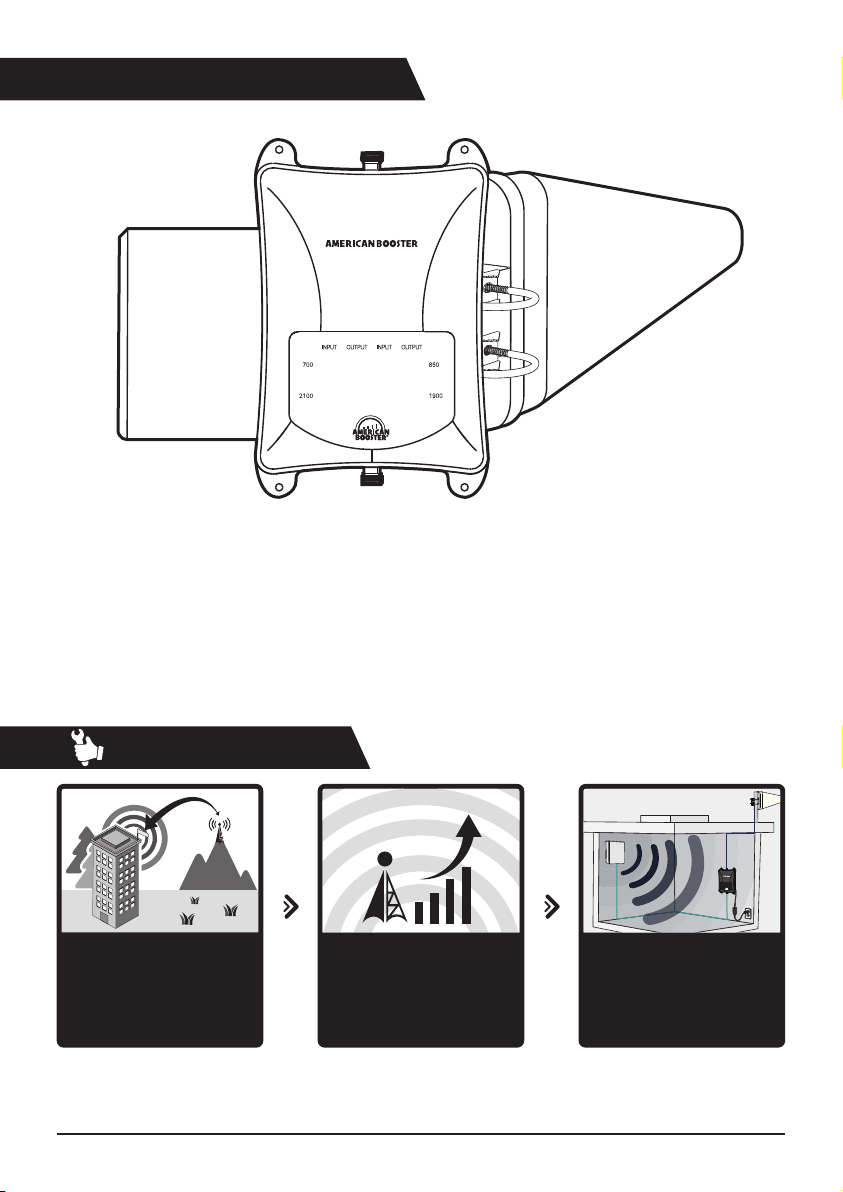
How it works
B-25K
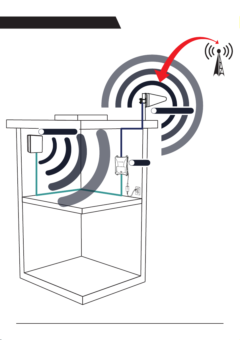
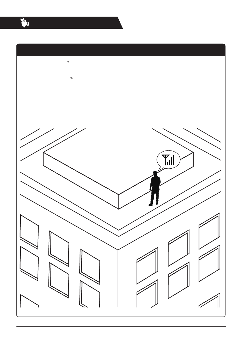
The signal booster’s outside
antenna receives voice and
data signals from a nearby
cell tower.
Receives Signal
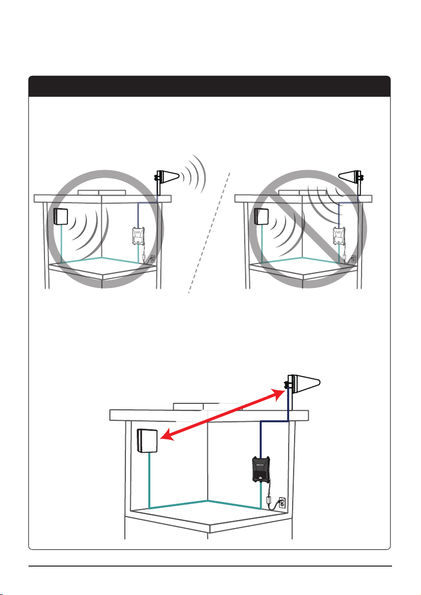
The inside antenna
distributes the boosted
signals inside your building.
Improves Signal
The signal booster receives
the signal from the outside
antenna and amplies the voice
and data signals.
Boosts Signal
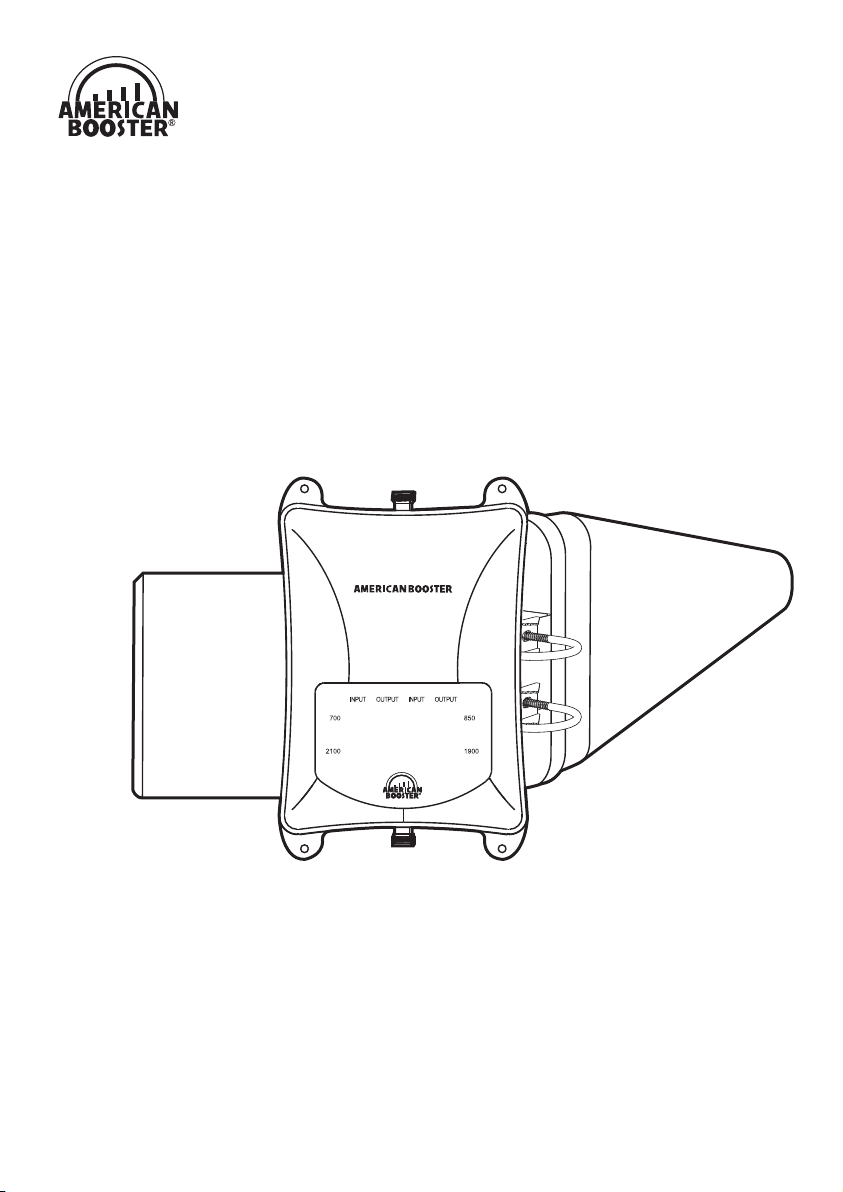
American Booster B-25K has been designed to improve and extend cellular coverage inside
the buildings. B-25K amplies signals from the nearest base station and re-transmits them at higher
power level. B-25K provides service at 700MHz LTE, 850MHz Cellular, 1900MHz PCS and 2100MHz AWS
frequencies without any additional setup or conguration.
B-25K
4
®
B-25K User Guide