HOME5000
700
850
1900
2100
HOME5000
700
850
1900
2100
HOME5000
700
850
1900
2100
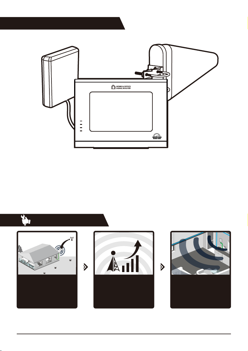
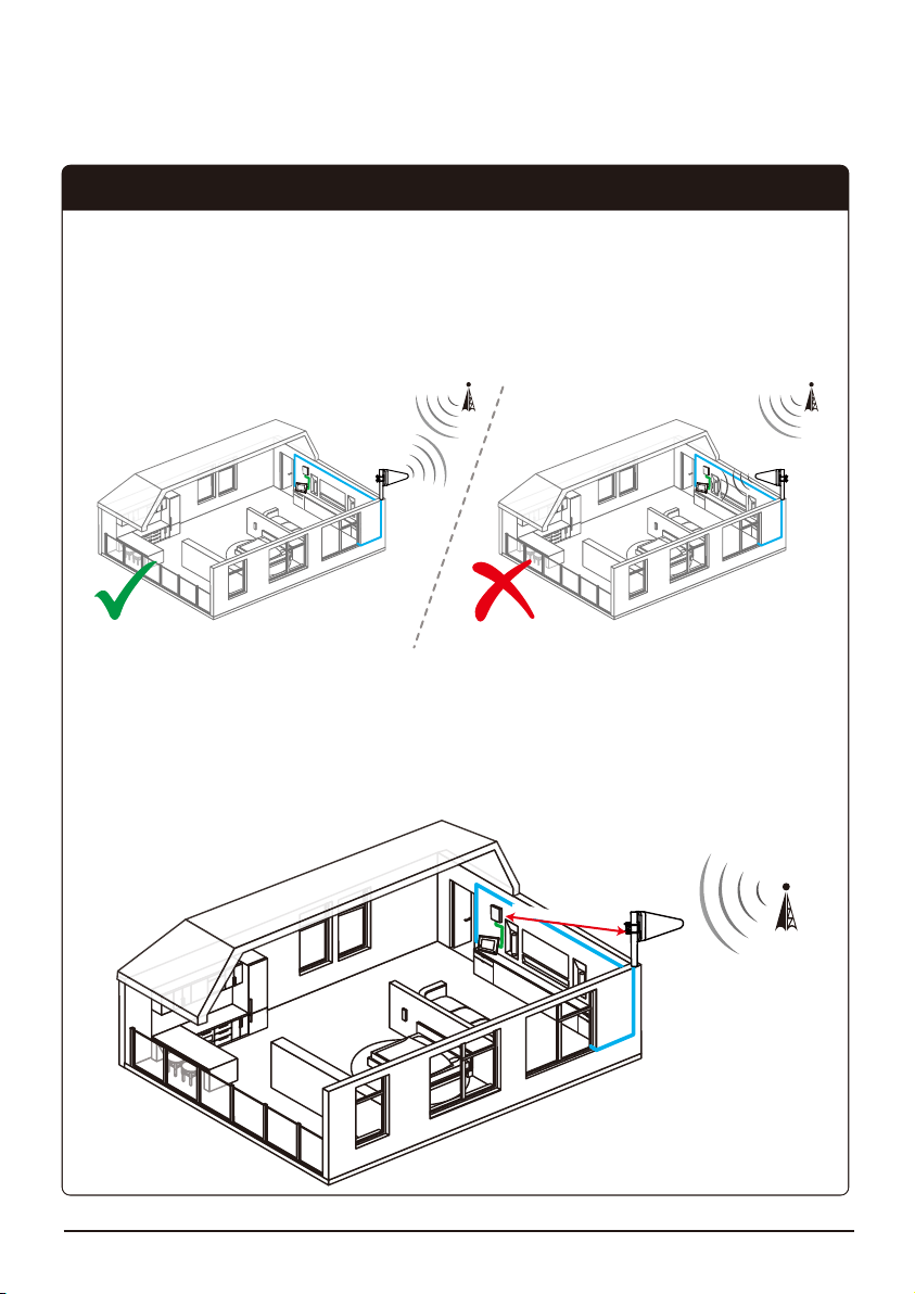
STEP 2. Install the Outside Antenna
The outside antenna is shaped like a triangle. This antenna must be mounted as high as possible
on the exterior of the house or oce, but never higher than 35 ft. above the ground.
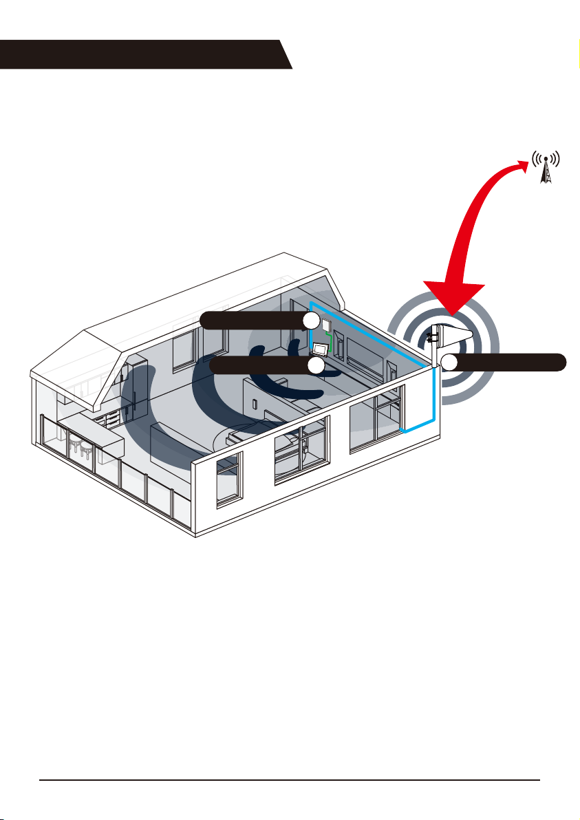
Mount the outside antenna on the side of the house where you detected the strongest cell phone
signal. The point of the antenna triangle should be pointed towards the location of the strongest
cell phone signal (which should also be the direction of the closest cell tower) and away from the
expected placement of the inside antenna.
For the best performance, the outside antenna and the inside antenna should be a minimum
distance of 20 ft. apart from each other. A bigger separation between outside antenna and
inside antenna will provide a stronger signal and better coverage.
Separation Between Outside Antenna and Inside Antenna
Antenna Separation 20 ft.
10 HOME 5000 User Guide