American Dynamics AD1983 User manual

Model
1983
Control
Code
Converter
Installation Instructions
The
1983
Code Converter, for use with American Dynamics switching systems, enables control
of
a Receiver at a
distant camera site via an
RS-232
communication link.
Two
Code Converters are required per
link:
one Code Converter
is
located
at the switching system end
of
the link and operating in a transmit mode. The other Code Converter
is
located
at the distant site and operating
in
a
receive mode.
A
switch
sets
the operating mode. In the transmit
mode,
Control
Code from the Switched Controller is converted to an
RS-232
signal. In the receive mode, the
RS-232
signals are
converted back
to
Control Code
for
Receivers at the distant camera sites.

Informationfurnished by AMERICAN DYNAMICSis believed
to
be accurateand reliable. However,no responsibilityis assumedby
AMERICAN DYNAMICSfor
its
use; norfor any infringements
of
other rightsof third parties which may result from
its
use. No license
is grantedby implicationsor otherwise under any patent or patent rights
of
AMERICAN DYNAMICS.
Copyright
@
1991
by American Dynamics. All rights reserved

--
-I
-I
-=AMERICAN
--
-JDYNAM/CS
I
I-
--
The
installation
of
this
product should
be
made
by
qualified
service personneland
should
conform
to
all
localcodes.
CAUTION
TO
REDUCE
THE
RISK
OF
ELECTRIC
SHOCK,
DO
NOT
REMOVE
COVERS
(OR
BACK)
.
NO
USER-SERVICEABLEPARTS
INSIDE.
REFER
SERVICING
TO
QUALIFIED
SERVICE
PERSONNEL
I
WARNING
To
reduce
the
risk
of
fire
or
shock
hazard, do
I
not expose this product torain
or
moisture.
Warning:
This
product generates, uses, and can
radiate radio frequency energy and if not
installed and used in accordance with the
instructions manual, may cause interference to
radio communications.
It
has been tested and
found to comply with the limits for
a
Class
A
computing device pursuant to Part
15
of
FCC
Rules, which are designed to provide reasonable
protection against such interference when
operated in
a
commercial environment.
Operation
of
this product in
a
residential area
is
likely
to
cause interference in which
case
the
user
at
his own expense will be required to take
whatever measures may be required to correct
the interference.
The lightning flash with arrowhead
symbol, within an equilateral
triangle,
is
intended to alert the
user to the presence of uninsulated
"dangerous voltage
"
with
i
n the
product's enclosure that may be of
sufficient magnitude to constitute
a
risk
of
electric shock
to
persons.
The exclamation point within an
equilateral triangle
is
intended to
alert the user to
the
presence
of
important operating and maintenance
(servicing) instructions in the
literature accompanyingthe product.
UNPACKING AND INSPECTION
Unpack carefully. This is an electronic product and should
be handled as such. Compare the items received with the
packing
list
with your order.
Be
sure tosave:
1.
The shipping cartons and insert pieces. They are the
safest material in which tomake future shipments of
the product.
2.
The IMPORTANTSAFEGUARDS sheet.
3.
These Installation and OperatingInstructions.
MAINTENANCE
User maintenance
of
this unit
is
limited to external cleaning
and inspection. For specific recommendations refer to the
IMPORTANT SAFEGUARDS sheet packagedwith this product.
INSTALLATION AND SERVICE
If you require information during installation of this
product or if service seems necessary, contact the
American Dynamics Repair and Service Department
at
(800)
442-2225.
You
must
obtain
a
Return
Authorization
Number and shipping instructions before returning any
product for service.
Do not attempt toservice this product yourself, Opening or
removing covers may expose you to dangerous voltages or
other hazards. Refer
all
servicingtoqualifiedpersonnel.
QA301
C


INSTALLATION
MOUNTING RS-232
Connector
The Code Converters are supplied as free
desk
mount standing
units. For rack mounting, use AD2117 Series Rack Mount kits.
Mount one of the
two
Code Converters
in
a convenient location
near the Switcher/Controller
or,
if used, a Code Distributor.
Mount the second at the distant site near the Receiver
to
be
controlled
to
minimize Control Code wiring. Avoid heat sources
or
poorly
ventilatedracks.
The %pin modular phone connector, labeled RS-232, is used on
the code converters for the RS-232 link.
This output can be used on a hardwire system up to 1000 ft.
between units. This output can
also
be used with user supplied
telephone modems
so
that a command can be sent over the
telephone lines.
CODE
UO
CONNECTIONS RS-232 CONNECTOR PINOUTS
The 12-pin
CODE
YO
connector on the rear panel
is
used for
connection
of
the required Manchester Code lines. See CODE
VO
PINOUTS
below. A mating plug is supplied. Connections
for Code Converters at the Switcher/Controller (Receive Control
Code/Transmit RS-232) and those at the distant site (Receive
RS-232Rransmit Control Code) differ.
Code Converter
at
SwitcherKontroUerSite:
Connect
a
shielded twisted pair, (Belden 8760 or equivalent)
from the Switcher/Controller to pins 10, 11, and 12
of
the Code
VO
connector.
This
line should
not
exceed a length
of
lo00
ft
(33Gm). See the manual for the individual SwitcherKontroller
in
regard to the control outputconnections.
Code Converterat the Distant Site:
Connect
a
shielded twisted pair, (Belden 8760 or equivalent)
code line from pins 1,2,and 3 of the Code
YO
connector, to the
Receiver
to
be
controlled. This
line
should not exceed a length
of
1000 ft. (330m). See the individual Receiver manual for
connection and Code
YO
Pinouts.
CODE
UO
PINOUTS
PIN FUNCTION PIN FUNCTION
1
XmitWHI Code 7
No
Connection
2 XmitBLKCode
8
No
Connection
3
XmitSHLD 9
No
Connection
4 XmitWHI
10
RecWHICode
5
XmitBLK 11 RecBLKCode
6
XmitSHLD 12 RecSHLD
PIN
1
2
3
4
5
6
7
8
FUNCTION
No
Connection
GND
No
Connection
XMIT
RCD
No
Connection
GND
No
Connection
The
line, phone, and
PSK
connectors are not used on this
unit.
BAUD RATE
The communication speed of the RS-232 is set at
9600
baud
prior to shipping.
To
changethe baud rate:
1. Disconnect the power.
2.
Remove the four screws (two on each side) with a Phillips
head screwdriver.
3.
Remove the top cover and turn the unit
so
that its front
is
facing
you
with the wording orientated in the upright
position.
4.The four possible baud rates (1200, 2400,4800, and
9600)
are
changed
by
moving a plastic jumper used
to
connect
one
of
the
four speed connectors. The four speed connectors are located in
the upper right hand side
of
the unit. The four different baud
rates are printed on the printed circuit
card
next to each possible
connection.
LINE
PHONE
RS232
CODE
PS
K
im
Figure 1
-
1983Code Converter
-
rear panel
1

INSTALLATION
SETUPat SwitcherKontrollerSite
All controls for the Code Converter are located on the unit's front
panel. The front panel controls determine if the unit receives
Control Code and converts it to RS-232 or receives RS-232 and
converts it
to
Control Code.
This switch should
be
set
to
correspond
to
the selectedbaud rate.
At
1200baud
-
4
Receivers may
be
controlled (position
4).
At
2400 baud
-
8 Receiversmay
be
controlled (position8).
At
4800 baud
-
12Receivers may be controlled (position 12).
At
9600 baud
-
16,
20,
or
24
Receivers may be controlled
(positions 16,
20,
24).
Power
The
unit
is
set
to
a
%oo
baud rate when shipped.
The 1983 Code Converter
is
supplied with an
ON/OFF
switch.
The unit is turned ON by pressing the bottom of the switch
labeled
"1";
and turned
OFF
by
pressing
"0".
Power is supplied
via a pendant cord and plug. Verify that the unit is
off
(power
switch set to
"0")
and connect the pendant cord into the required
power
source.
See
Specifications
in
the back
of
this
manual.
DATA
OdOff
Switch
-
Set this switch to
OFF
initially. This places the
Code Converter off line. See the OPERATION section for
further
information.
Xmit/Rec Switch
-
This switch determines the direction
of
the
RS-232
data
flow.
When this switch is placed in the XMIT
position, it will receive Control Code from a Switcher/Controller
and transmit this
data
as
ASCII characters in RS-232 format.
When placed in the REC position, the Code Converter will
receive the ASCII characters via RS-232, and convert the
data
to
Control
Code
for the receivers.
RECEIVERSCONTROLLED
This switch selects the quantity of Receivers to
be
controlled by
the code converter, working in conjunction with the camera
section.
The position
of
the switch indicates the number
of
Receivers controlled and must correspond to the operational
baud
rate
(see
below).
Note: If the setting of the Receiver Controlled switch
is
greater
than the maximum number allowed by the baud rate, then only
the maximum number will be controlled.
For
example,
if
the
setting on the Receiver Controlled switch
is
set to 16, and the
baud rate is
4800,
then
only
12Receivers will
be
controlled.
CAMERA
There are
two
switches associated with the CAMERA section of
the front panel. These two switches are BLOCK and START.
These switches are used
to
decide which block of
64
cameras the
control code will
be
used
for
and the starting camera number
of
the block.
Block
-This is a
10
position rotary switch. Positions one through
eight
are
used
to
select the block
of
cameras the code converter is
to be used for. The remaining two positions
of
the rotary are not
used. The selections areas follows:
POSITION
1
2
3
4
5
6
7
8
CAMERA
BLOCK
1-64
65
-
128
129
-
192
193
-
256
251
-
320
321
-
384
385
-
448
449
-
512
DATA
&-
STATUS
-+
RECEIVERS
r-CAMERASq
Rs292 CODE
ON
XMT
Gala
;&$
;y:,
OFF
REC
7
a
57
CONTROLLED
BLOCK
START
I
Figure
2
-
1983Code Converter
-
front panel
2

OPERATION
Start
-
This is a 10-position
rotary
switch. Positions one through
eight are used to select the starting camera number of the group
of
eight cameras that the code converter is
to
be used for. The
remaining
two
positions of the rotary are
not
used. The setting of
this switch in conjunction with the Receiver Controlled switch
will select the cameras to be controlled.
The starting camera number selections are as follows:
POSITION
1
2
3
4
5
6
7
8
CAMERA
NUMBER
1
9
17
25
33
41
49
57
SETUP At Distant Site (at Receiver)
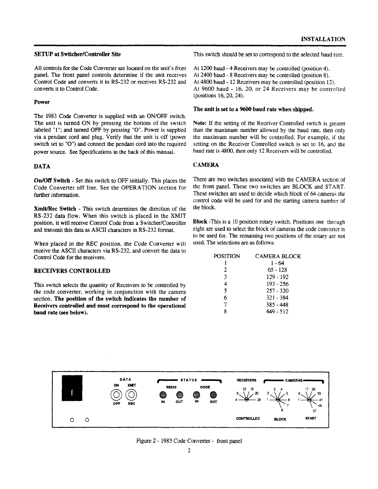
All
controls
for
the Code Converter
are
located on the unit's front
panel. The front panel controls determine if the unit receives
Control Code and converts it to RS-232 or receives RS-232 and
converts it to Control Code.
XMIT/REC
Switch
-
Set this switch to REC. this places the
code converter in the receive mode.
RECEIVERS CONTROLLED
Switch
at the Distant Site
-
The setting of this rotary switch
on
the code converter at the
distant site
is
irrelevant.
CAMERA
Switches at
the
Distant Site
-
The setting of these
two rotary switches
on
the code converter at the distant site is
irrelevant.
OPERATION
Power
Switch
Place the unit into operation by depressing the side of the switch,
marked "1". See the Power section
on
page 1 for further
information.
Front Panel Indicators
Four
indicator
lights on the front panels of each code converter
indicate
status
and
operation. See below.
RS-232 OUT
-
This indicator, when lit, indicates data is
being transmitted to the link by the code converter in the XMIT
mode.
Code In
-
In the XMIT mode this light indicates the
presence of proper Control Code commands from the
Switcher/Controllerinto the code converter.
In
1600,
1650,
and
1700
systems, and from a
1680MG
Generator, the Code In light glows steadily whenever proper
Control Code is present. A flickering light may
be
an indication
that
the
B
and
W
wires of the Control Code line have been
reversed.
In 1995 and 2050 systems, it glows steadily only while proper
Control Code commands are being received from the Switched
Controller.
Code Out
-
In REC mode this light indicates that the proper
Manchester Control Code commands are being sent from the
code converter
to
a Receiver. It lights each time a proper Control
Code command is sent
out.
ControlCode Transmission
When connections and setup are complete and the
communication link has been established between the code
converters,the link is ready to transmit Control Code.
To
transmit ControlCode
perform
the following steps in order:
1.
Turn
on
both converters by depressing the
"1"
side
of
the
power switcheson the left of the front panels.
2.
Move the DATA
ON/OFF
switch to
ON.
It is found
on
the
code converter
at
the Switcher/Conuoller (XMIT mode).
3.
Move the DATA
ON/OFF
Switch
to
ON,
found on the
code
converter at the distant site (REC mode). The RS 232 light will
now flash
on
both code converters when the Control Code
commands for the Receiver at the distant site are sent
from
the
Switcher/Controller.The Code-Out light on the code converter at
the distant site will flicker each time a word is sent to
a
Receiver
at
the site.
RS-232
IN
-
This indicator, when lit, indicates
data
is being
received from the link by the code converter in the
REC
mode.
3

An American Dynamics Product
Designed and built by
Sensormatic CCTV Systems Division
One Blue Hill Plaza
Pearl River, New York, 10965
(914) 624-7600
Technical Support Center: 1-800-442-2225
FAX: 914-624-7685
8000-0897-01 OP0292Z
October 1991 Printed in USA
SPECIFICATIONS
Power Source: AD1983 120V, 50/60 Hz Nominal
AD1983X 230V, 50/60 Hz Nominal
Power: 10 Watts Nominal
Size: 1.88”H X 10.3”D
Weight: 2 lbs, (1.5 Kg) approx.
Temperature: 0 to 49°C (32° to 120°F)
Humidity: 0 to 95% relative
This manual suits for next models
2
Table of contents
Other American Dynamics Media Converter manuals

American Dynamics
American Dynamics VideoEdge User manual

American Dynamics
American Dynamics RCSN422 User manual

American Dynamics
American Dynamics RCSN422 User manual

American Dynamics
American Dynamics VideoEdge User manual

American Dynamics
American Dynamics RCSN422 User manual

American Dynamics
American Dynamics AD2091 User manual

American Dynamics
American Dynamics VideoEdge Quick start guide

American Dynamics
American Dynamics ADEIP8M User manual

American Dynamics
American Dynamics AD2083-02C User manual

American Dynamics
American Dynamics AD RS-422 User manual