BMR SFU-0303 Series User manual
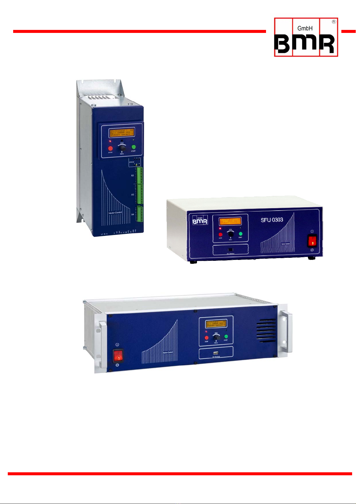
Frequency Converter SFU-0303
SSE
Version
Desktop
Version
19" Version

SFU-0303 M a n u a l
E - 2 -
Content
1 Introduction
2 Description and Features
3 Block Diagram
4 Technical Data
4.1 Version SSE
4.2 Version 19" and Desktop
5 Safety Precautions and Warnings
6 Connections, Interfaces and Pinout
6.1 Version SSE: Digital and Analogue Inputs X2
6.2 Version SSE: Digital und Analogue Outputs X3
6.3 Version SSE: Spindel Interface X4
6.4 Version SSE: Mains Connector, Spindle Connector
6.5 Version 19" and Desktop Version: Digital and Analogue In- and Outputs
6.6 Version 19" and Desktop Version Spindel Interface
6.7 Version 19" Mains Connector, Spindle Connector
6.8 Version Desktop: Mains Connector, Spindle Connector
6.9 Version SSE: RS232, RS485 X1
6.10 USB Connection
7 Functions, Setup, Operation
8.1 Front panel of SSE, Desktop and 19"Version
8.2 Converter Start and Stop
8.3 Status LED Display
8.4 LCD-Operating Panel
8.5 Setup of Rotational Speed
8.6 Safety Functions
8.7 Safe Power Stage Pulse Lock according EN 954-1 K3
8 Profibus
9 Setup with Windows-Software
10 Automatic Spindle Tuning
11 Examples for Connection
11.1 Mains and Spindle Connection
11.2 Logic and Wiring for Safety
12 EMC
13 Troubleshooting
14 General Hints
15 Warranty
16 Accessories
17 Mechanics and Dimension
17.1 SSE Version for cabinet mounting
17.2 19" Version
17.3 Desktop Version

SFU-0303 M a n u a l
E - 3 -
1. Introduction
Due to its construction, the rotational speed of a 3-phase AC motor is directly dependent on the
number of poles and the frequency of the network. In case of a 3PH 50Hz network and a 2-pole
motor, the nominal speed would be 50 rps * 60 = 3000 rpm.
In case of BLDC motors (brushless dc), the speed is directly dependent on the voltage applied.
3-phase AC motors provide numerous benefits in industry, such as brushless operation, freedom
from wear and tear, favourable capacity/weight ratio, high-speed capability, and much more.
These motors can be used many different application areas, such as milling and grinding
spindles, or with drilling machinery, for example.
The advantages of SFU0303 compared to similar converters:
- Safe Power Stage Pulse inhibitor, authorized to current regulations EN 954_1 Categorie 3
- Maximum Power in industrial network up to 5kVA
- High efficiency by symmetrical PWM
- Real time vector control for sensorless operation
- Maximum Torque even at lowest rotational speeds
- High possible acceleration rates for short process times. For example 25.000rpm/sec with a
2,2 KW Motor (with robotic applications)
- Pulse-Amplitude (PAM / =Block-Modus ) Control possible because of regulated intermediate
voltage control (on option)
- Very slow rotational speeds (10rpm) possible for reaching tool changer positions.
- Very low current consumption because of real time power control
- Easy Integration into new and existing PLCs because of flexible I/O configuration
- Various interface options: Profibus, RS485, RS232, USB
- Easy reversing the direction of rotation by Software without loss of power.
- Autotuning function for spindle setup.
- Testrun with graphical documentation of voltages and currents of the spindle
- Up to 16 different spindle characteristics can be stored
- Very user-friendly debugging interface for setup control
- Start/Stop Interface for periodical tests or remote control
- Operating panel is detouchable and can be used as remote control together with an
extension cable
- Designed for roughest use in industrial environment
- The housing of SSE is realized without ventilations slots and an outside mounted heatsink.
preventing by this the intrusion of dirt and chips of tooling.
- Very compact case style makes easy cabinet mounting possible

SFU-0303 M a n u a l
E - 4 -
- Several case options for cabinet mounting (SSE) , 19" rack style and desktop, or special
designs on request
- User friendly Screw-plug connector system for power-, spindle- and I/O connectors.
- Wide range of operating voltage 115V-230V
- Automatic deceleration of the spindle down to standstill in case of mains failiure by "Back
Energy" Function
- Plain text display in amber color
- Very user friendly operation menu.
- USB connection and RS232 with specific adapter cable
- Full functional without operation panel in remote configuration
- Remote control hand-terminal available
- Controlled fan
- Datalogger-Function on option available in combination with PC software SFU-Terminal.
Records of all relevant parameters of the converter in nearly infinite lengths are possible
down onto the PC- hard disc.

SFU-0303 M a n u a l
E - 5 -
2. Description and Features
•Operation of Asynchronous AC und BLDC Motors
•The high frequency converter SFU-0303 makes possible rotational speeds
with 2pole AC-Motors up to 500.000rpm and with BLDC-Motors up to 100.000rpm
•High output power ( 3,6kV @ 230V / 2kVA @ 115V ) in compact style
•The core of SFU-0303 is a Digital Signal Processor (DSP) which produces all output signals and
collects all input signals
•All parameters like current, voltage and frequency are collected in real time and are regulated by
the implemented vector control depending on the load condition.
•High precision sinusoidal output signals with low distortion factor realize very high accuracy in
rotional behaviour.
•Allows highest efficiency of the spindles at low and high frequencies
•High operational safety: All operating conditions like acceleration, operation with nominal
rotational speed, deceleration is monitored and critical conditions are intercepted.
•Integrated braking resistance (brake chopper). Without brake chopper the deceleration times
down to standstill can be longer.
•Transparency: The user is always informed about the current status of the converter and the
spindle on a plain text and detachable operating panel at the front panel.
•Control: If needed, the converter can be controlled and parameterized manually with a pluggable
operating unit.
•Easy reversing the direction of rotation by Software without loss of power.
•Individual adjustment to the current application and the connected spindle. Up to 16 different
characteristics can be stored in the converter
A variety of options for control and communication possibilities: For communication with
peripheral devices, such as PC, PLC or CNC, there are 3 ports available:
•Easy and flexible integration into existing equipments by free configuration of I/Os
Control inputs: 2 Analog, 6 Digital
Control Outputs: 2 Analog, 6 Digital (Relay)
•Galvanic separation of all interfaces from each other and from mains / spindle potential
•Short circuit proof
•Comfortable Configuration und control with the help of a PC-Windows software "SFU-Terminal"
•Cloning-Function with operating panel: Creating of clones of converters by individual read out
of the SFU-parameters into the operation panel and download into another or multiple SFUs.
•Automatic spindle calibration by autotuning function

SFU-0303 M a n u a l
E - 6 -
3. Block diagram
picture1
SFU-0303 M a n u a l
E - 7 -
4. Technical data
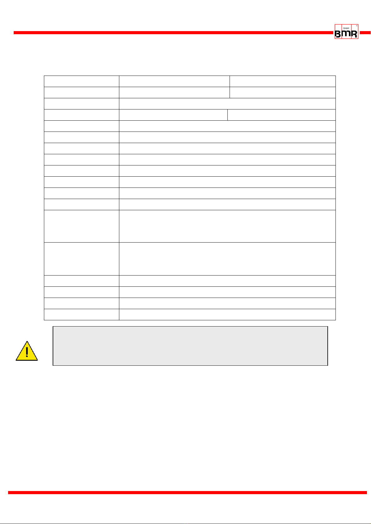
4.1 Version SSE
Mains connection 115V, 60Hz, 1PH 230V, 50Hz, 1PH
Output power Max 2 kVA Max 3,6 kVA
Motor connection 10-polig: PE,U,V,W, PTC, FP, SGND pluggable screw clamps 4mm2
Output voltage 3* 110V 3* 220V
Output current / power limited electronically
Over-current maximal duration adjustable 0…20sec
Output frequency AC: max 8,8kHz / 500.000 rpm DC: max 100.000 rpm
Spindle characteristics max. 16, stored internally
Spindle Sensor inputs PTC, Speed sensor / Hall sensor, Logic: 9 pin pluggable screw clamps X4
Control inputs 2 Analog: 0-10V, separated galvanically: 10 pin pluggable screw clamps X2
Control inputs 6 Digital: 0-24V, separated galvanically: 10 pin pluggable screw clamps X2
Control outputs 2 Analog: 0-10V, separated galvanically 12 pin pluggable screw clamps X3
Control outputs 5 x Digital, free to be setup
1 x Digital reserved for power stage pulse inhibitor
outputs on Relays, 24VDC/1000mA, 125VAC/500mA
12 pin pluggable screw clamps X3
Interface - USB on operating panel USB-Mini
- RS232, RS485 am SFU 9 pin DSub male
- Profibus on option as module, without operating panel
dimensions see chap 17
Weight ca. 4 kg depending on option
Protection IP20
Operating conditions max ambient temperature 40°C, no humidity
ATTENTION
The operation of a spindle with a wrong characteristic may harm the spindle
severely!
Please ensure to have the proper characteristic selected always!
SFU-0303 M a n u a l
E - 8 -
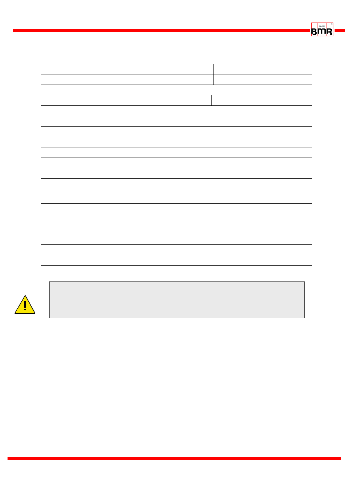
4.2 Version 19" und Desktop
Mains connection 115V, 60Hz, 1PH 230V, 50Hz, 1PH
Output power Max 2 kVA Max 3,6 kVA
Motor connection 9-polig: U,V,W, PTC, FP, SGND 2xPE, screw clamps 4mm2
Output voltage 3* 110V 3* 220V
Output current / power limited electronically
Over-current maximal duration adjustable 0…20sec
Output frequency AC: max 8,8kHz / 500.000 rpm DC: max 100.000 rpm
Spindle characteristics max. 16, stored internally
Spindle Sensor inputs PTC, Speed sensor / Hall sensor, Logic: 15pin D-Sub female
Control inputs 2 Analog: 0-10V, separated galvanically: 25pin D-Sub female
Control inputs 6 Digital: 0-24V, separated galvanically: 25pin D-Sub female
Control outputs 2 Analog: 0-10V, separated galvanically 25pin D-Sub female
Control outputs 6 Digital: outputs on Relays, 24VDC/1000mA, 125VAC/500mA
25pin D-Sub female
Interface - USB on operating panel used at the desktop, only
- RS232, RS485 am SFU 9 pin DSub male
- Profibus on option as module, without operating panel
dimensions see chap 17
Weight ca. 4 kg depending on option
Protection IP20
Operating conditions max ambient temperature 40°C, no humidity
ATTENTION
The operation of a spindle with a wrong characteristic may harm the spindle
severely!
Please ensure to have the proper characteristic selected always!

SFU-0303 M a n u a l
E - 9 -
5. Safety-Precautions and Warnings
•This device produces dangerous electrical voltages and is used for the operation of dangerous
moving mechanical parts. For this reason, only professionally trained and qualified personnel
should be allowed to install and repair this device!
•The operation with disconnected PE connection is not allowed.
•Any maintenance or repair work to the device must only be carried out after the supply voltage
has been disconnected!
•Before the first commissioning can be carried out, it should be established that the motor is
installed correctly and securely, to eliminate the possibility of uncontrolled movement of the
motor.
•Safety regulations that are valid for the country where the device is used, have to be adhered to
where any work is carried out on the device.
•Maintaining EMC (electromagnetic compatibility) limits is the responsibility of the manufacturer of
the machine or device. The inputs and outputs on this device are fitted with filters, to increase the
interference immunity and reduce emitted interference, making it possible to use this device in an
industrial environment.
•The EMC of a machine or device is affected by all connected components (motor spindle, length
and type of cables, wiring, etc). Under certain conditions the use of additional filters can be
necessary to maintain the current laws.
•For the reasons listed above, installation and connection of the device should be carried out by
qualified personnel only.
6. Connections, Interfaces and Pinouts
For embedding into PLC and controls the SFU0303 has several input and outputs.
These are realized as pluggable screw terminals and lead out at front and rear panel (depending
on case option). All contacts are separated galvanically from high voltage carrying circuits.
Operational parameters and outputs:
The SFU-0303 covers all current important operational parameters and operating data.
Up to 6 digital outputs can be used for signalling and up to 2 analogue values can be output to
the analogue outputs (0-10V) .
Remote Control and Outputs:
6 digital inputs (24V) and 2 analogue inputs (0-10V) are available for remote control of the
SFU-0303.
These assignments can be configured freely. By using the optional Windows PC software "SFU-
Terminal" the above mentioned assignments can be achieved easily, providing exceptional
flexibility with each application.
Each operating parameter can be assigned as a signal and each control signal can be allocated
the required I/O pin. In addition, the logic level (high or low active) can be individually defined.
The same assignment is also possible for the analogue measured data and control data at the
analogue I/O pin.
The standard allocations of operational parameters, their outputs, control signals and inputs, are
listed in the following tables.

SFU-0303 M a n u a l
E - 10 -
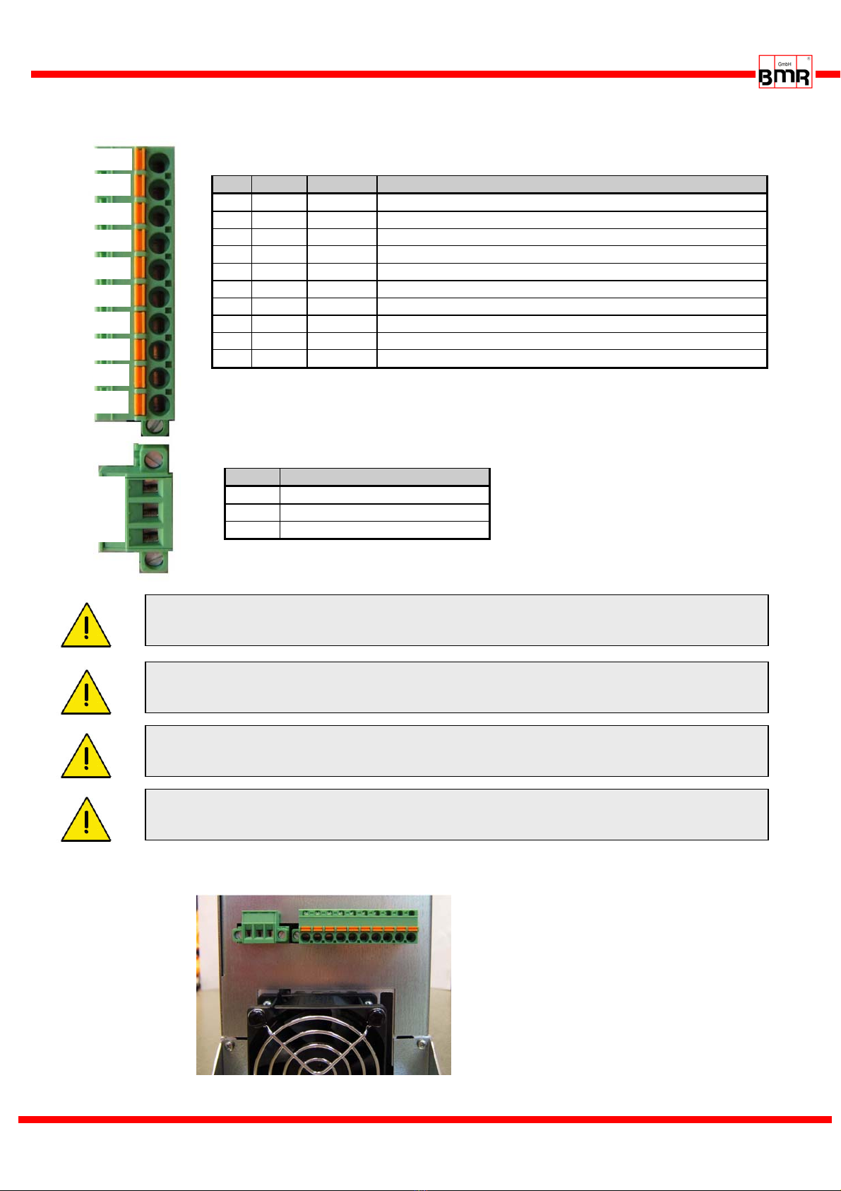
6.1 Version SSE: Digital and Analogue Input X2 (10 pin Pluggable screw terminal)
Picture2
Pin Description Direction Function / default Setting switching state
1 Digital In 1 Input Start - Stop "0" Stop / "1" Start
2 Digital In 2 Input Power Stage Pulse Lock "0" activated / "1" released
3 Digital In 3 Input Power stage Off "0" Aus / "1" On
4 Digital In 4 Input Locked / Emergency Stop "0" released / "1" Emergency Stop
5 Digital In 5 Input Error reset "0" Errors have to be reset, with Hi
level on this Input or with any Start
signal
"1" Errors are reset automatically
6 Digital In 6 Input Direction of rotation "0" unchanged / "1" inverted
7 Analog In 1 Input Set value Rotational speed
Scaling 10V min/max
8 Analog In 2 Input Set value Varioload
9 GND PWR Ground reference for die
Digital und Analog signals
10 +24V/50mA Output Auxiliary voltage supply
The Default-settings of the functions for the outputs can be set up freely with the help of the PC-
Software SFU-Terminal.
•Switching level digital inputs: Log"0" = 0…7V / Log"1" = 18….24V SPS Standard level
•Analogue input range: 0…10V
•The +24V at Pin 10 can be used as auxiliary voltage supply for Start / Stop signal with the help of
a relay or for an electronic spindle interface.
SFU-0303 M a n u a l
E - 11 -
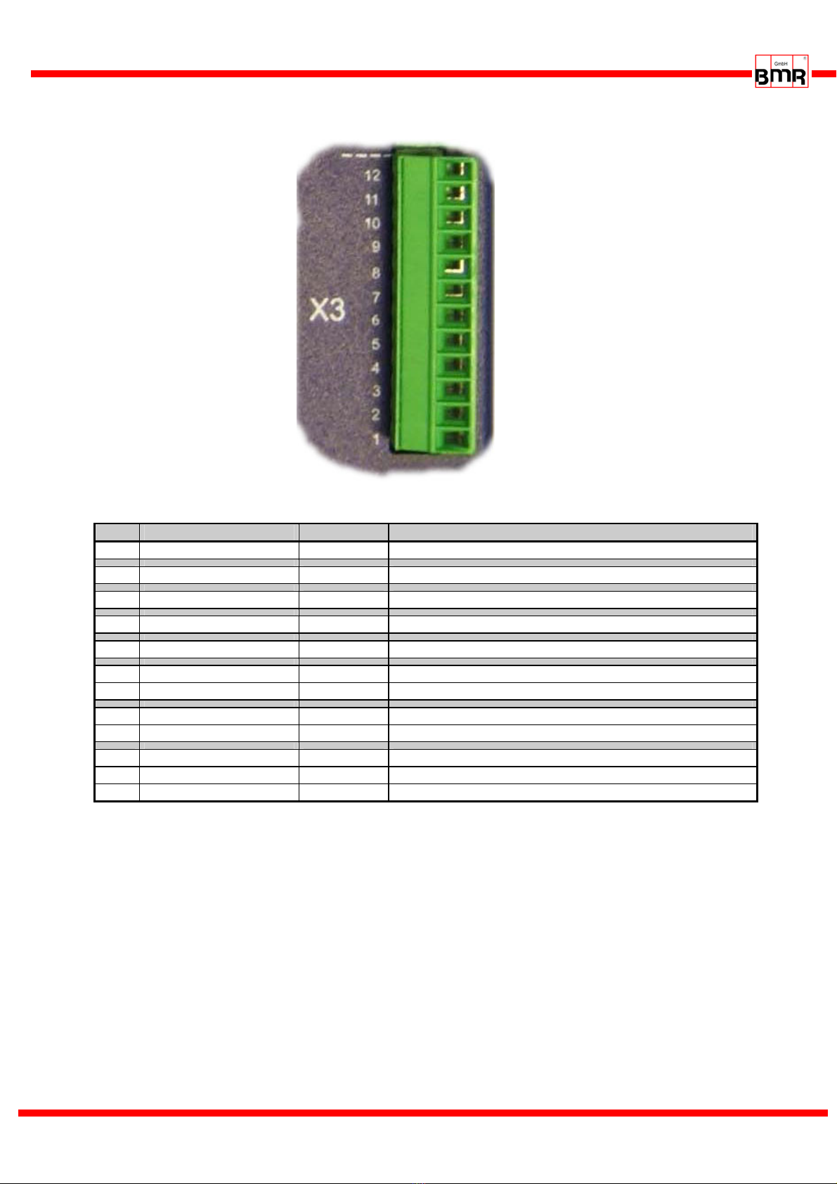
6.2 Version SSE: Digital and Analogue Outputs X3 (12 pin Pluggable screw terminal )
Picture3
Pin Description Direction Function / Message / default Setting
1 RelayCommon Common Rail Relay 1..5
2 Relay6 Normally closed Output Feedback signal for Power Stage Pulse Lock state
3 Relay5 Normally closed Output Excess temperature Converter or Spindle
4 Relay4 Normally closed Output Overload
5 Relay3 Normally closed Output Standstill Converter and Spindle
6 Relay2 Normally closed Output Spindle Ready
7 Relay2 Normally open Output
8 Relay1 Normally closed Output Converter Ready
9 Relay1 Normally open Output
10 Analog Out 1 Output
11 Analog Out 2 Output
12 Hall Sensor-Output Output modified signal square shape signal from encoder
The Default-settings of the functions for the outputs can be set up freely with the help of the PC-
Software SFU-Terminal.
An exception is the signal "Power Stage Pulse Lock", which is linked fix with Relay 6. According to the
switch state it will be output 0V / GND or +24V via 10kΩreferring to GND (X2.9) (-> 8.2 / 8.7)
+24V: Power Stage released 0V: Power Stage locked.
•The digital outputs (Relay1...5) are galvanically separated (500VIsolation).
DC: 24V / 1000mA AC: 125V / 500mA
•Output level Speed / Hall Sensor: 0-24V (24V Level)

SFU-0303 M a n u a l
E - 12 -
6.3 Spindle Interface X4 (9 pin Pluggable screw terminal)
Picture4
Pin Description Direction Function / default Setting
1 +12V/50mA Output Auxiliary voltage supply
2 Spindle GND Ground reference
3 NC Not connected
4 Speed sensor input Input Input for 2/3-wire speed sensors / Hall sensor from spindle
5 PTC Input Temperature signal from Spindle / KTY as Option
6 Bit 4 Input automatic Spindle detection
7 Bit 3 Input automatic Spindle detection
8 Bit 2 Input automatic Spindle detection
9 Bit 1 Input automatic Spindle detection
The Default-settings of the functions for the outputs can be set up freely with the help of the PC-
Software SFU-Terminal. The inputs of the encoder and the PTC are fix wired.
•The spindle interface is separated with optocouplers from all other signals. It can be used for an
automatic spindle detection, if activated. The logic levels are low-active by default: "HI" > PIN
connected with Spindle-GND, "LO" > PIN open. In the menu "Digital Inputs" this can be changed.
•The input "PTC" is provided for detection of excess temperature of the spindle. If the resistance
between PTC and GND is > 600Ω, the error message ‘Excess temperature Spindle’ is set and a
safety shut down is carried out after expiring of the delay time.
•On option a temperature detection for KTY is possible. This requires a HW modification.
•The input 4 for the speed sensor works in the range of +/- 1V with a common mode range of
0..10V.
•The +12V at Pin 1 can be used as auxiliary voltage supply
SFU-0303 M a n u a l
E - 13 -
6.4 Mains and Spindle connection at SSE
Picture 5
View at screw terminals at version SSE
Picture 6
Pin Name Direction Function
1 +VFP Output Auxiliary voltage supply for active speed sensor 12V/50mA
2 SGND Ground reference for signals FP, PTC
3 FP Input Input for 2/3-wire speed sensors / Hall sensor
4 PTC Input PTC Temperature signal from Spindle / on option KTY
5 W Output Spindle Phase W
6 V Output Spindle Phase V
7 U Output Spindle Phase U
8 Rext Output External Brake resistor / Chopper Resistor
9 +ZU Output Intermediate voltage (! Attention, High Tension !)
10 PE Connection for protective earth of the spindle. ! Safety !
Name Function
PE Protective Earth ! Safety !
N Null
L Phase
+VFP
SGN
D
FP
PTC
W
V
U
Rext
+ZU
PE
L
N
PE
Control wires, Mains cables and spindle cables should be installed separately.
For wiring, the use of shielded cables is recommended.
The device has no internal fusing. It has to be fused externally
Please ensure, that PE protective earth is connected at the spindle side as well
as at the mains side.
Please ensure, that PE protective earth is connected at the mains side. The
device must not be operated without properly connected PE!
SFU-0303 M a n u a l
E - 14 -
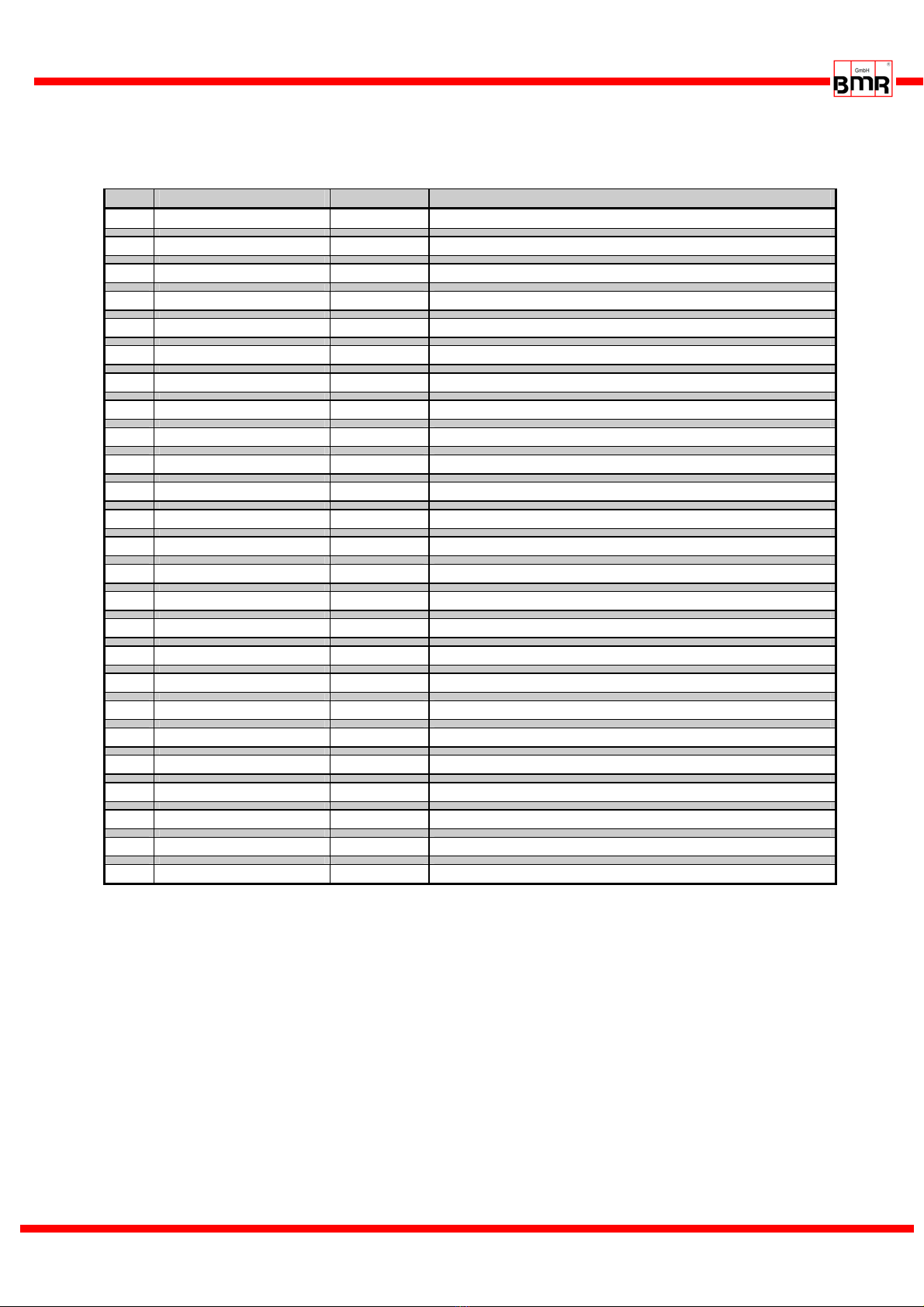
6.5 Version 19" und Desktop:
I/O Interface - Digital and Analogue In- and Outputs (D-Sub 25pin female)
Pin Description Direction Function / Message / default Setting
1 Relay Common Common Rail for Relay contacts
14 Relay Common
2 Relay 1 Normally Closed Output
15 Relay 2 Normally Closed Output
3 Relay 3 Normally Closed Output
16 Relay 4 Normally Closed Output
4 Relay 5 Normally Closed Output
17 Relay 6 Normally Closed Output Feedback signal for Power Stage Pulse Lock state
5 Relay 1 Normally Open Output
18 +24V/50mA
6 +24V/50mA
19 GND
7 GND
20 Relay 2 Normally Open Output
8 Hall Sensor Output Modified signal from speed sensor
21 Digital In 2 Input Output Stage Pulse Blocking
9 Digital In 6 Input
22 Digital In 5 Input
10 Digital In 4 Input
23 Digital In 3 Input
11 Digital In 1 Input
24 Analog In 1 Input
12 Analog In 2 Input
25 Analog Out 1 Output
13 Analog Out 2 Output
The Default-settings of the functions for the outputs can be set up freely with the help of the PC-
Software SFU-Terminal.
An exception is the signal "Power Stage Pulse Lock", which is linked fix with Relay 6. According to the
switch state it will be output 0V / GND or +24V via 10kΩreferring to GND (7, 19) (-> 8.2 / 8.7)
+24V: Power Stage released 0V: Power Stage locked.
•The digital outputs (Relay1...5) are galvanically separated (500VIsolation).
DC: 24V / 1000mA AC: 125V / 500mA
•Analogue input range 0…10V
•Output level Speed / Hall Sensor: 0-24V (24V Level)
•+24V at Pin6, 18 may be used as auxillary power supply for e.g. an electronic spindle interface
SFU-0303 M a n u a l
E - 15 -
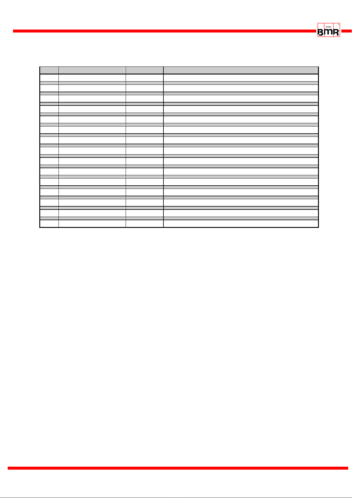
6.6 Version 19" und Desktop: Spindel Interface (D-Sub 25pin female)
Pin Name Direction Function / default Setting
1 NC
9 +12V/50mA Auxiliary voltage supply
2 GND
10 GND
3 Bit 0 Input automatic Spindle detection
11 Bit 0 Input automatic Spindle detection
4 Bit 1 Input automatic Spindle detection
12 Bit 1 Input automatic Spindle detection
5 Bit 2 Input automatic Spindle detection
13 Bit 2 Input automatic Spindle detection
6 Bit 3 Input automatic Spindle detection
14 Bit 3 Input automatic Spindle detection
7 PTC Input Temperature signal from spindle
15 PTC Input Temperature signal from spindle
8 Hall Sensor Input Speed signal from speed sensor from spindle
The Default-settings of the functions for the outputs can be set up freely with the help of the PC-
Software SFU-Terminal. The inputs of the encoder and the PTC are fix wired.
•The spindle interface is separated with optocouplers from all other signals. It can be used for an
automatic spindle detection, if activated. The logic levels are low-active by default: "HI" > PIN
connected with Spindle-GND, "LO" > PIN open. In the menu "Digital Inputs" this can be changed.
•The input "PTC" is provided for detection of excess temperature of the spindle. If the resistance
between PTC and GND is > 600Ω, the error message ‘Excess temperature Spindle’ is set and a
safety shut down is carried out after expiring of the delay time.
•On option a temperature detection for KTY is possible. This requires a HW modification.
•The input 4 for the speed sensor works in the range of +/- 1V with a common mode range of
0..10V.
•The +12V at Pin 1 can be used as auxiliary voltage supply

SFU-0303 M a n u a l
E - 16 -
6.7 19" Version: Mains and Spindle connection
Back side SFU0303-19" with spindle connector clamp terminal Picture 7
Spindle Connector - 9pin clamp terminal
Mains connection - 9pin clamp terminal
Pin Name Direction Function
1 +VFP Output Auxiliary voltage supply for active speed sensors 12V/50mA
2 SGND Ground for signals FP, PTC
3 FP Input Input for two/three wire-speed sensors
4 PTC Input temperature signal of spindle or as option KTY
5 W Output Spindle phase W
6 V Output Spindle phase V
7 U Output Spindle phase U
PE PE
PE PE Connection for protective earth of the spindle. ! Safety !
Name Function
PE protective earth ! Safety !
N Neutral
L Phase
Sicherun
g
sautoma
Spindle connection Mains Connection
A
utomatic Fuses
Spindle Interface I/O Interface
Control wires, Mains cables and spindle cables should be installed separately.
For wiring, the use of shielded cables is recommended.
Please ensure, that PE protective earth is connected at the spindle side as well as at the
mains side.
Please ensure, that PE protective earth is connected at the mains side. The device must
not be operated without properly connected PE!

SFU-0303 M a n u a l
E - 17 -
6.8 Desktop Version: Mains and Spindle connection
The connection with mains network is carried out with an IEC connector
The device is equipped with a Thermo-Automatic Fuse for each prong. They can be reset after tripping
by pressing down the button
The spindle connection is realized on custom order and can be realized accordingly
Backside SFU0303-Desktop equipped with a 7pin circular spindle connection Picture 8
Spindle Connection 7pol. female Binder Series 693 or Amphenol C16-1
6 SGND Signal GND for PTC- and FP-Signal
5WSpindle Phase 3
4 FP for speedsensor of the spindle
7 PE Protective Earth
3VSpindle Phase 2
2 PTC for temperature sensor of the spindle
1USpindle Phase 1
IEC Mains connection
Sicherungsau
A
utomatic Fuse
S
p
indle connection
Control wires, Mains cables and spindle cables should be installed separately.
For wiring, the use of shielded cables is recommended.
I/O Interface S
p
indle Interface
SFU-0303 M a n u a l
E - 18 -
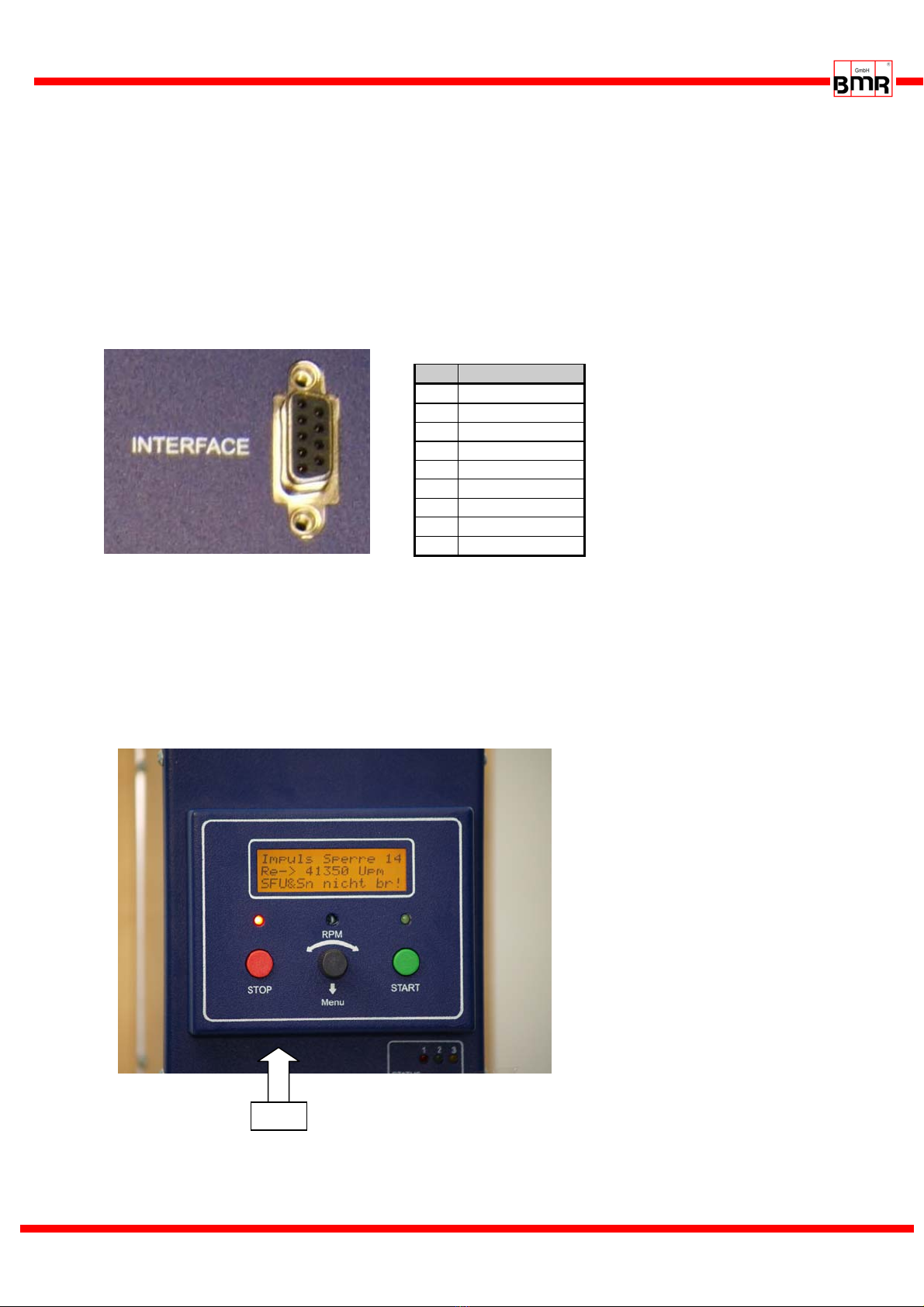
6.9 RS232, RS485 - X1 at Version SSE
At SSE devices the connection X1 INTERFACE is provided for the operating panel. A RS232 and a
RS485 interface is wired to this connector. The 19" and desktop versions have built-in operating
panels which are not detachable.
With disconnected operating panel a connection to a PC or any control can be established with a
specific BMR cable. A standard cable wont work or may harm the device.
The operating panel is fixed with 2,5mm Allen screw to the SFU0303. After unfixing the operating
panel can be removed. Additionally it can be used as a remote control in conjunction with a 1:1 cable.
Picture9
6.10 USB-Connection
For easy connection and communication, the device is equipped with a USB interface. At the version
SSE it is located at the bottom side as USB Mini AB. At the 19" and Desktop devices, it is found at the
front panel directly below the display.
Picture10
Pin Function
1 Release
2 NC
3 A-RS485
4 RxD-RS232
5 GND
6 +5V-RS
7 NC
8 B-RS485
9 TxD-RS232
USB

SFU-0303 M a n u a l
E - 19 -
7. Functions, Commissioning, Operation
7.1 Front panel SSE, Desktop and 19" Version
picture 12 front panel Desktop
picture 11 front panel SSE
picture 13 front panel 19" version

SFU-0303 M a n u a l
E - 20 -
7.2 Starting of the Converter and Power Stage Pulse Lock
Spindle Characteristics
All converters of BMR need an information about the basic data of the spindle, such as maximum
voltage, current, rotational speed, and many more. These are stored in so called "spindle
characteristics". A BMR spindle characteristic has 16 setpoints within the range of the rotational
speed. At every point data of voltage, current, load scaling, acceleration and deceleration ramp and
many more data can be defined and this for idle load as well as for full load. And there are in total 16
places for different characteristics. The spindle characteristics are the key for any spindle and give a
possibility to control the running behavior at every load condition.
In advance of start of a spindle first, it has to be ensured, that the proper characteristic is selected and
activated. This is generally the case if the device is delivered together with a spindle and the required
setup is done. If the converter and spindle are delivered separately, the proper spindle characteristic
has to be loaded into the converter first. This can be achieved with the free setup software SFU-
Terminal, easily.
In case of being unsure, characteristics for most common spindles are available at BMR.
Start and Stop
There are different possibilities for starting and stopping SFU0303, due to many different
requirements, as follows below:
Generally, a STOP can be triggered by the source of START, with the exception of an Emergency
Stop, activated Intermediate voltage lock or any other safety function.
- Start button at operating panel, Rotational speed with encoder potentiometer
- Pure serial control with commands via USB / RS232 / RS485 / Profibus interface
- Digital input in combination with an activated analogue input for control of rotational speed.
In case of not being activated, the rotational speed is setup with encoder poti on operating
panel or via serial commands.
Power Stage Pulse Lock
Precondition for proper starting is a released power stage pulse lock (Bridge X2.2 – X2.10), as well as
a proper characteristic for the connected spindle.
The converter of the 0303 series are equipped with an safety power stage pulse locking circuit which
has to be wired properly for operation. For activating the power stage a voltage with carrying a high
signal should be applied to digital input 2 / PIN2. The voltage can be fed from PIN10. So, easy as
possible simply a bridge between PIN2 and PIN10 will do this. The feedback signal about the status is
displayed on the operating panel, if equipped, on LED6 and on relay output 6 at connector X3.
Attention! Without this connection the converter cannot be started.
The power stage pulse lock is realized according the requirements of EN954-1 Category 3 for safe
stop of drives. (-> Chap 8.7) +24V: Power Stage released 0V: Power Stage locked.
Status
The current status of the converter is displayed on the status LED display and with mounted operating
panel the status is displayed in plaintext on the LCD-display, additionally.
This manual suits for next models
1
Table of contents
Other BMR Media Converter manuals


