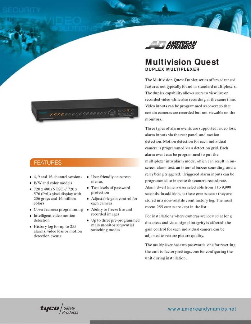
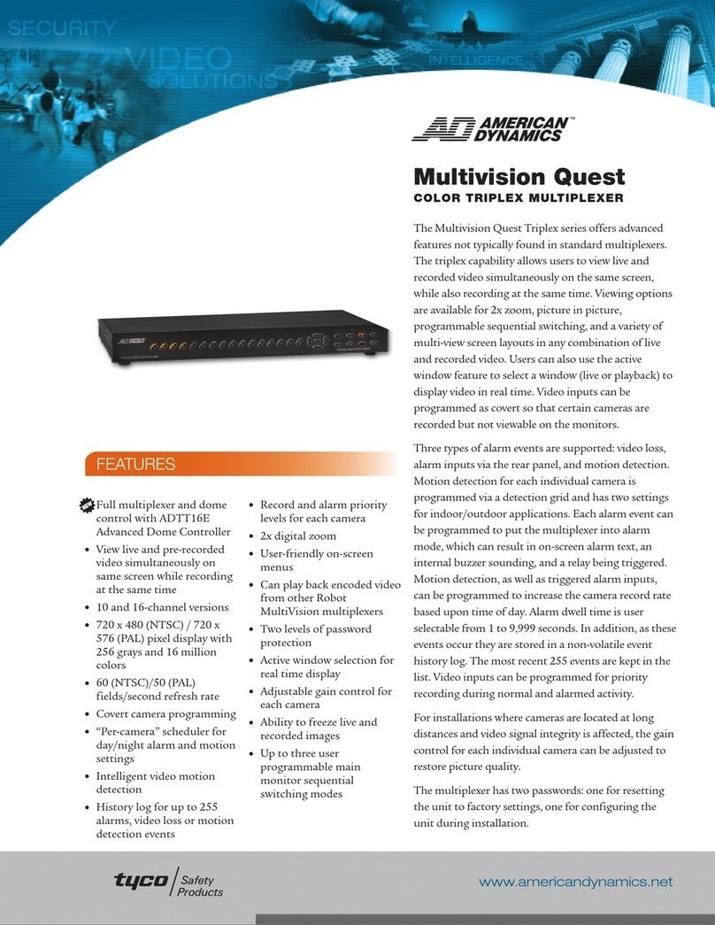
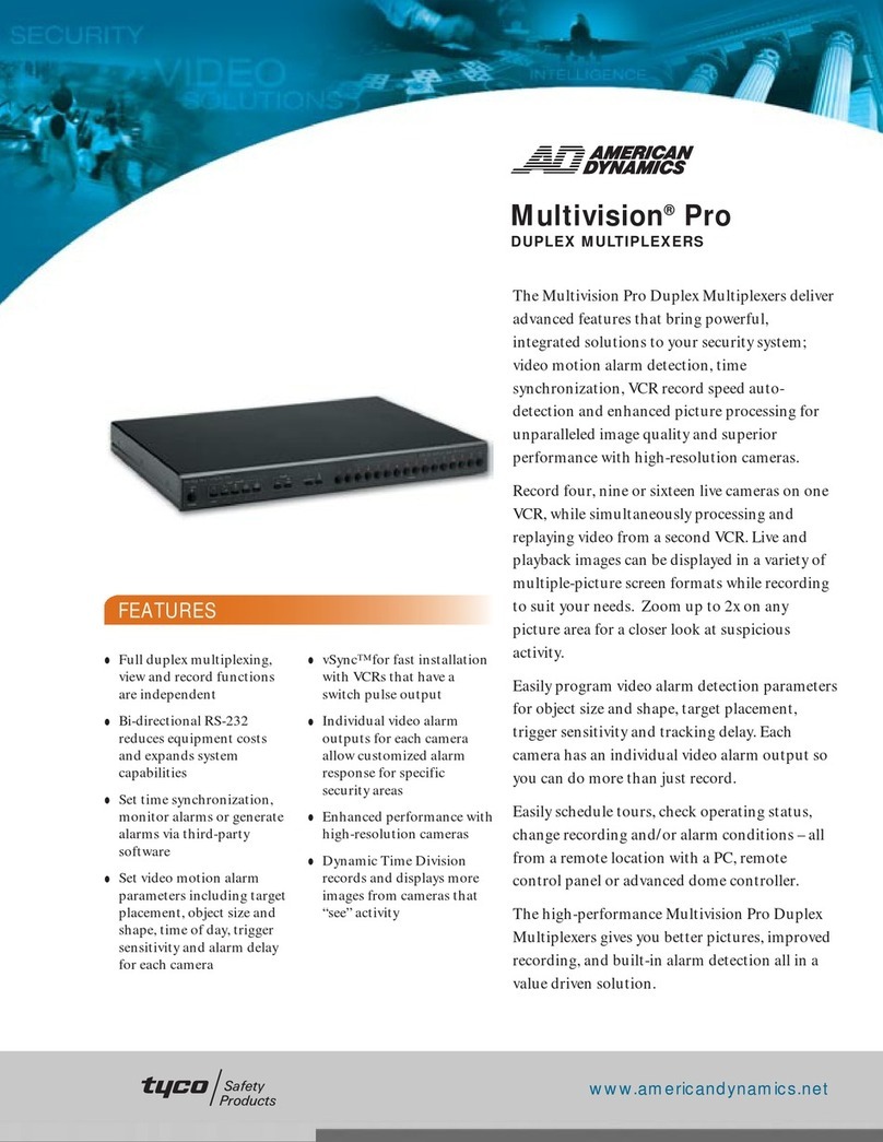
American Dynamics AD1473 User manual

Model
1473
QuadView
I1
Installation and Operating Instructions
This
manual describesthe installation
and
operating procedures forthe
American
Dynamics model
1473
QuadView
11.
The
1473
QuadView
11,
a four quadrant multiplexer, digitally captures the video from four
video
sources, reduces these images to quarter-
screen size, and combines them onto a QUAD output.
A
separate
CALL
output provides full
-
screen viewing of each input
contained
in
the quad presentation.
Alarm
inputs
and
remote controls provide optimum flexibility
in
alarm viewing and
reoordiag.

The
softwate
furnished with this equipment
is
confidentialto is copyrightedby AMERICAN DYNAMICS. It
is
ad
to
be
copied
or
disclosed
in
any manner without
the
express written consent of AMERICAN DYNAMICS. The software is furnished to the
putchaser
under
a license
for
use
on
a
single system.
Information
furnished
by
AMERICAN DYNAMICS
is
believed to
be
accurate and reliable. However, no responsibility is
assumed
by AMERICAN DYNAMICS for
its
use;
nor
for
any
infringements
of
other
rights
of
third parties
which
may
result
from
its
use.
No
license
is
granted
by implications
or
otherwise under any patent orpatent
rights
of AMERICAN DYNAMICS.

-
-
-1
-
I
-=AMERICAN
-
-
-
>DYNAMICS
I
-
-
-
I
The installationof this product should be made by qualified
service personneland should conformto
all
local codes.
CAWm
TO REDUCE
THE
RISK
OF
ELECTWC SHOCK,
W
NOT
REMOVE
COVERS
(OR
BACK)
.
NO
USER-SERVICEABLE
PARTS
INSIM.
REFER
SERVlClNG
TO
QUALIFIED
SERVICE PERSONNEL
WARNING
To
reduce
the
risk
of
fire
or
shock
hazard,
do
not
expose this product
to
rain
or
moisture.
This product generates and uses radio frequency
energy
and
if
not
installed and used properly, that is,
in
strict accordance with the manufacturer's
instructions, may cause interference to radio
and
television reception.
It
has been type tested and found
to comply
with
the limits for a Class
B
computing
device
in
accordancewith the specifications
in
Part 15
of
FCC
Rules, which are designed toprovide reasonable
protection against such interference
in
a
residential
installation. However, there is no guarantee that
interference will not occur
in
a
particular installation.
If
this product does cause interference to radio
or
television reception, which can be determined by
turning
the
product
off and
on,
the user is encouraged
to
try
to
correct the interference by one or more
of
the following measures:
-
Reorienttheproduct.
-
Relocate
theproduct
with
respect tothe receiver.
-
Move
the product away
from
the receiver.
-
Plug
the
product
into a different outlet
so
that the
prdct
and
receiver are
on
different branch circuits.
If
necessary, the user should consult the dealer or an
experienced radio/television technician for additional
suggestions. The user may
find
the following bookket
prepared
by
the Federal Communications Commission
helpful:
"
How to Identify and Resolve Radio-TV
Interference Problems." This booklet is available
from
the
U.S.
Government
Printing
Office, Washington,
DC
20402,
Stock
N
O
.
004-000-00345-4.
The
lightning flash with arrowhead
symbol, within
an
equilateral
triangle, is intended to alert
the
user to the presence of uninsulated
"
d
a
ng
e
rou
s
voltage
"
within
t
he
product's enclosure that may be of
sufficient magnitude to constitute
a
risk
of
electric shock topersons.
The exclamation point within an
equilateral triangle is intended to
alert the user to the presence of
important operating and maintenance
(servicing) instructions in the
literature accompanyingthe product.
UNPACKING AND INSPECTION
Unpack carefully. This is
an
electronic product and should
be handled as such. Compare the items receivedwith the
packing list with your order.
Be
sure tosave:
1. The shippingcartons and insert pieces. They
are
the
safest materialinwhich tomake future shipments of
the product.
2.
The IMPORTANT SAFEGUARDS sheet.
3.
These Installationand Operating Instructions.
MAINTENANCE
User maintenance of this unit is limited to external cleaning
and inspection. For specific recommendations refer to the
IMPORTANT SAFEGUARDS sheet packagedwith this product.
INSTALLATIONAND
SERVICE
If
you require information during installation of this
product or
if
service seems necessary, contact the
American Dynamics Repair and Service Department
at
(800)
442
-
2225.
You
must obtain
a
Return Authorization
Number and shipping instructions before returning any
product for service.
Do not attempt toservice this product yourself. Opening
or
removing covers may expose you to dangerous voltages
or
other hazards. Refer all servicing toqualifiedpersonnel.
QA303C
Table
of
Contents
System Description
................................................
1
Features
..................................................................
1
Installation
..............................................................
1
Connections
............................................................
2
Setup
......................................................................
3
Operation
................................................................
4
Typical SystemConnections
....................
Appendix
Troubleshooting
............................
Inside Back Page
Specifications
..........................................
Back Page

.
.
..
1
2
3
4
DESCRIPTION, FEATURES
and
INSTALLATION
SELECT
-
FUNCTIOW
El
mm
FREEZE
RUN
ALARYS
ElmIElmm
1
2
s
1
QUAD
CQ
Ss,"A,WEW
I1
Figure
1
-
1473
QuadView
11
=STEM
DESCRIPTION
The
1473
QuadViw
11,
a four quadrant multiplexer, digitally
captures
the video
from
four standard video
sources,
reduces
these
images
to quarter-saeen
size,
and combines
them
into a
single video
output
utilizing a Quad display of
all
four videos.
One
1473
output provides the quad
-
type presentation.
A
second output provides full
-
screen viewing
of
each input
contained
in
the
quad
presentation. Alann inputs and outputs
and
remote
control
inputs
provide optimum flexibility
in
alarm
viewing, recording, and control.
FEATURES
*
Both Quad and Call monitor
outputs
(SeeFigure
2)
*
On
-
screen Quad displaysinclude camera number
Built
-
in switcher sequencesfill
-
screen camera displays on
the Call
monitor.
with
or
without the Quad display
*
Manual
or
remote
"
FREEZE
"
instantly immobilizes the
Quad display
forfurther
inspection
*
Manual
or
remote call
-
up
of
each camera
or
the Quad
display
on
the Callmonitor
*
Automatic
call
-
up
of
alarmed cameras to the Call monitor
when
the
corresponding
alarm
input
is
activated: multiple
alarmsare sequenced
on
the Call monitor
*
Threedifferem
Ahnn
Clearance
modes
are available:
1.
Alarm
cleared whenacknowledged
2.
Alarm
automaticallycleared afrer
20
secondsor when
3. Alarm automaticallycleared when alarm input is cleared
alarm input
is
cleared,whichever isthe longer
*
Loss
of
video
at
any input
is
detected and indicated
on
the
Quad
display
by displaying
a
blank screen.
INSTALLATION
This
installation should
be
made
by
qualified service personnel
and should conform to
all
local codes. Safeguards
must
be
taken to avoid unintentional operation by employees
and
maintenance personnel working about the premises, by falling
objects, by customers, by building vibration, and by similar
causes.
Mounting
1473
QuadView
I1
desktop and rack
-
mount models
are
available. Mount
unit
in
a convenient
location
near associated
monitors. Avoid heat sources or poorly ventilated
racks.
Operating
temperatures must
be
held within areasonablerange
to
insure
proper
operation.
IF YOU ENCOUNTER ANY PROBLEMS
OPERATINGTHIS UNIT, OR NEED TECHNICAL
ASSISTANCE, CALL OUR SERVICECENTER AT:
within the United States 1
-
800
-
442
-
2225
outsidethe United States (845) 624
-
7640
Quad
Monitor
Call
Monitor
*
Verticaf
Sync
lock
to
Camera
1
or
to
the
AC
line
Figure
2
-
Four
-
Camera OutputDisplays
*
Looping video inputs
1

~~
-
CONNECTIONS
a3
HI2
I
78 Oha
V'DEo-oUT
MS.
REMOTE CONTROL. RLY
0
'Eli
@,
@
@I
@
1234
+234aFR~
%A
%
0000000000000000
m
m
m
CALL
QUAD
I
HU
I
75
Ohm
Hi2
I
75 Ohm
HI2
I
75 Ohm
Figure
3
-
1473
Rear
Panel
CONNECTIONS
Alardemote
Controls
video
Inputs
Four
pairs
of BNC connectors (1, 2, 3, 4)
are
used
for video
inputs. The camera connected to a BNC automatically is
assigned the corresponding on
-
screen camera number. The
two
-
position slide switch, under each video input pair,
configuresthe input terminationin one of
two
ways:
Right (75
Ohm):
Terminateseach input in
75 ohms.
Left
(HiZ):
Used
forunterminated, looping input.
Set the slide switches to
the
right position
if
the signals
are
terminated at the QuadView
II
or to the left if the signal is
looped to another video device (the looping signal must
eventually
be
terminated).
Conned
up
to
four
video
sou~ces
to
BNC inputs
1,2,3,
and
4
on the rear panel. All video inputs must be 1 Vp
-
p,
2:l
interlaced,
RS
-
170
or
CCIR
standard,
composite video signals.
Use
a
good
grade
of
75
-
ohm
coaxial cable (such as Belden
8241
or
equivalent)
with
BNC connectors.
Vidco Inputs
1
thru
4
are
displayed on the
Quad
monitor
in
a
quad configuration. The displays
are
also shown on
the
Call
monitor, each display
in
a full
-
screenconfiguration.
Video
Outputs
Two VIDEO
OUT
BNCs, CALL and QUAD, are used for
outputs
to
monitors, VCR's, etc. The video output signals
are
1
Vp
-
p,
RS
-
170 or
CCIR
standard, composite
video.
Each
output must
be
terminated
in
75
ohms
at
the
end
of
its
run.
If
one
monitor is
used,
connect it to the Call output.
If
two
monitors
are
used,
connect one to
the
Call output, which can
be
used
as
a sequence monitor, and one to the Quad output,
which alwayspresents the quad
format.
PowerconnectifM
Connect the appended 3
-
wire cord to the required power
source
according to the model. The operating voltage is shown
on
the
rear panel.
1473 12OVAC,50/60Hz
1473X 23OVAC,
50/60
Hz
The 16
-
pin AlarmdRemoteControVRly connector on the rear
panel is for input of alarm signals from user
-
supplied
alarm
devices, for remote control inputs, and for access to relay
contactsactivated by
alarms.
ALARMS
-
Inputs to the
ALARMS
connections
1
thru
4,
from user
-
supplied alarm devices, activate the
alarm
functionsand
call
the corresponding video input. Using the
factory supplied cable, connect
Alarm
Ground Closures to
Alarm
Inputs
1,
2, 3, and
4.
The contact returns should
all
return to the ground
pin
(pin
5)
of
the
alarm
connector.
"
1
"
(pin 1)
"
2
"
(pin
2)
"
3
"
(pin
3)
"
4
(pin
4)
'I+'
(pin
5)
Ground
Alarm
Input
1
Alarm
Input
2
Alarm
Input
3
Alarm
Input
4
REMOTE
CONTROL
-
Full function remote control is
provided via hard
-
wire contact inputs to the REMOTE
CONTROL
connections, 1
thru
A.
Each contact must
be
momentarily closed
to
ground (pin
5)
to activate the remote
function. These remote inputs operate identical to the front
panel functions,
as
described
on page 4, Operation.
"
1
"
(pin
6)
"
3
"
(pin
8)
"
4
(pin
9)
"
Q
"
(pin
10)
"R
(pin
12)
"
A
(pin 13)
"
2
"
(pin
7)
"
F
(pin 11)
Call
Camera
1
Call
Camera
2
Call
Camera 3
Call
Camera
4
Quad
Freeze
RUn
Alarm
(Acknowledgeor Enable)
RLY
(Relay Contact
Outputs)
-
A
Form
-
C relay provides
two outputs,
one
normally open, the other normally closed,
which activate during almsfor control of a VCR
or
other
remote device. Relay contacts are for low
-
voltage control
circuitry only. Contact rating of this relay is: 0.6 Amps,
120VAC or 2.0 Amps, 30 VAC.
pin
14
Normally Open relay
pin
15
Common
pin
16 Normally Closed relay
2

SETUP
SETUP
Alarm
Modes
(Jumpers
J30,
J29, J28,
and
J27)
~~
Each individual camera input
can
be
set to different modes of
alarm
clearance. Set cameras
1,
2,
3,
and
4
to the different
alarm modes by moving jumpers
J30, J29, J28,
and
J27
respectively
to
the
desired positions
(see
Figure
4).
The
three
alarm
mode positions for eachjumper
are:
CAUTION
-
Due
to
the presence of non
-
insulated
compomnts
with
hazardous voltages, the
followinginternal adjustmentsshould
be
perfonnea
by qualifiedservicepersonnel only.
Color
Filters(Jumpers
J38,
J4)
The
1473
QuadView
I1
does not pass color signals on the
QUAD
output
In
order
to
use
signals from color
cameras
as
the input
to
the Quadview
II,
it
may
be
necessary
to
reduce the
color
sub-carrier
interference. Internal filters
are
provided and
may
be
activatedby moving internal
jumpers.
These
filters
do
not affect
color
signals
on
a full
-
screen
CALL
output. The
factory
setting
of
these
jumpers
isfarblack and white cameras.
Jumper
J38
reduces the color sub
-
carrier interference from
video inputs
1
and
3;
J4
reduces the color sub
-
carrier
interfexence
from
video ioputs
2
and
4.
See
jumper locations
in
the
1473
PCB
layout drawing, Figure
4.
Do
not move any
other
jumpers
as
seriousdamage could result.
MODE
1:
Holds the alarm until acknowledged either by
pressing the ALARMS pushbutton
or
by
an
input
of
a
remote
alarm
acknowledge, pin
13.
MODE
2:
Holds the
alarm
for twenty seconds for
an
alarm
input of twenty seconds
and
less. For longer
alarm
inputs,
holds
the
alarm
as
long
as
alarm
input is active.
Alarms
can
be acknowledged at
any
time during the
alarm
either
by
pressing the ALARMS pushbutton
or
by a remote
alarm
acknowledgeinput.
MODE
3:
Holds the
alarm
while the
alarm
input is active.
Alarms
can
be
acknowledged
at
any time
during
the
alarm
either by pressing the
ALARMS
pushbutton
or
by
a
remote
alarm
acknowledge input.
Quad
Sequence
Modes
(Jumpers
J39
and
J3
1)
Vertical
Lock
(Jumper
J33)
The
video
output
of
the Quadview
II
can
be
vertically locked
to
either
video
input
1
or
to
the
AC
line.
As
shipped, it is
locked
to
the
AC
line.
It
can
be
locked to
video
input
1
by
moving the
SYNC
jumper
(J33)
located on the
PCB
(see
figure
4).
To
add the Quad picture to
both
the
RUN
sequence and the
alarm
sequence,move the two
-
positionjumper
J39
to
the
"
IN
"
position (see Figure
4).
When
this
jumper is set to
the
"
OUT
"
position,
both
sequencesare only the full
-
screencamera inputs.
The
RUN
sequence rate, either
two
or
four
seconds,
is selected
by
the twcqositionjumper
J3
1.
0
0
f-
QuadSequenceModeJumpeers
J3s
J31
Alarm
Mode
Jumpers
Color
Cameres2and4
Filter
for
&
J29
J27
cdor
Filter
for
cameras1and3
2
J33
VerblcalkiACorCameral
J9
J10
J37
a8
J38
534
s17
536
J19 s16 J12 J14
~15
J13
I
lll_II
II
in[
II
iqn
I
II
I
Figure
4
-
1473
PCB
Layout

OPERATION
SELECT
7
FUNCTIOk
Fl
FIm
FREEZE
RUN ALARMS
mp!lmElm
1
2
3
1
QUAD
Q
~O"IDYI.tv
I1
Figure
5
-
Front Panel Controls
OPERATION
The
1473
QuadView I1 may be used
with
one
or
two monitors.
If only one monitor is used,
it
should
be
the Call Monitor. The
Call Monitor displayseither:
1.
A sequence of full
-
screen camera pictures,
with
or
without
the
Quad
Display
(see
RUN,
below).
2.
A
selected full
-
screen picture of
any
camera or the Quad
Display
(see
1,2,
3.4,
and QUADbelow).
The
Quad Monitor always showsthe Quad Display.
Front
Panel Operation
A
white
box
is displayed
in
the bottom center of the Quad
display when alarmsare enabled (Figure
5).
2. If
any alarm is active on a camera
input,
the
ALARMS
action is an acknowledge
of
the
alarm
(see
Alarm
Mode
Setup,page
3).
Video
Loss
Detection
Loss
of video to any input is detected by the
1473.
When
a
video loss is detected, the corresponding quadrant displays a
blanked screen on
the
Quad display. The last picture received
before video loss is stored
in
memory. If the FREEZE
pushbutton
is
activatedfollowinga video loss, the frozen Quad
display includes
the
last picture received, shown
in
the
appropriate quadrant
The
front panel controls (seeFigure
5)
operate
as
follows.
Alarm Action
1,
2,3,4:
Each of these pushbuttons
calls
a full
-
screendisplay
of
the correspondingcamera to the Call Monitor.
QUAD
This pushbutton calls a display of four cameras
(in
a
Quad
configuration) to the Call Monitor.
FREEZE:
Alternate
pushbutton
FREEZE
action:
1.
Freezes the current Quad display on both the Call and
Quad
Monitors. The Quad display
also
flashes
the word
"
FROZEN
"
(see Figure
6)
and shows the last picture
received before video loss,
if
video loss had been detected.
2.
Restoresthe real-time Quad display.
RUN:
The
RUN
pushbutton action sequences the four camera
inputs on the Call Monitor. The sequence rate, either two
or
four seconds,
is
selected by the jumper
J3
1.
To
include
the Quad display
in
the sequence, set jumper
539
to the
"
IN
"
position
(see
Quad SequenceSetup, page
3).
Activating the
RUN
pushbutton while a sequence
is
running
has
no effect. Activating any of the
1,
2,
3.4,
or
QUAD
pushbuttons stops the sequence and calls the requested
display
to
the
Call
Monitor.
ALARMS:
The
ALARMS
pushbutton action depends on the
current mode of the
unit:
1.
If
no
alarms
are active, alternate
ALARMS
pushbutton
action
enables
or
disables
alarm
response action
in
the unit.
Alarm
contact closures on
any
of the
Alarm
Input pins activate
the following response actions
if
the unit isenabled for
alarms:
1.
The word
"
ALARM!
"
flashes on the Quad display to
indicate the presence of
an
alarm (Figure
6).
2.
The Call Monitor displays a full
-
screen picture of one, or a
sequence of multiple, alarmed cameras. The Quad display
may be included
in
this sequence by the setting of jumper
J39
(see
Quad Sequence Setup, page
3).
Alarm
sequence
dwell time is
fmed
at
two seconds.
3.
The Form-C
alarm
relay is activated for control of
external
devices.
Each individual camera
can
be
set for one of three different
alarm
clearance modes, selectable by a
three
position jumper
(see
Alarm Modes Setup,page
3).
After the
alarm
is cleared or
acknowledged, the Call Monitor display
returns
to
the camera
it
was lastdisplaying,before the
alarm
occurred.
Blinks when an alarm is received
Blinks when Quad display is frozen
White
box
displayed when
alarms are enabled
Figure
6
-
FrozedAlam Quad Displays
4

Appendix


TYPICALSYSTEM CONNECTIONS
AD1473 QUADVIEW
II
Cameras and
Alarm
Contacts
CALL
Monitor
i0
ol
a4
1473
I
Camera
2
L
Camera
3
QUAD
Monitor
!€MoEcoHTRDL-RLY
I
Camera
4
\
LL
RemoteControlContacts

SPECIFICATIONS
Voltage
Input:
1473:
12OVAC,
50/60
Hz
1473x3 230
VAC,
50/60
Hz
Power:
7
watts
Video
Input/Output:
1473: RS
-
170
Standard,
NTSC
Video,
1
V
pp
1473X:
CCIR
Standard,
PAL
Video,
1
V
p
-
p
Alarm
Relay
Contacts
0.6A
@
120VAC,
2.OA
@
30VDC
Temperature:
-18“C
(0%)
to
54T(13ooF)
Humidity:
0
to
95
%
RH
(non
-
condensing)
Size:
Desktop
-
1.88”
H
x
10.5”
D
x
17”
W
(48
x
268
x
4311t~n)
Rack
Mount
-
1.75”
H
x
10.5”
D
x
19”
W
(45
x
268
x
482mm)
Weight:
8
lbs. (3.6
Kg)
An
AmericanDynamics
Product
Designed and built by
Sensormatic Video Systems Division
One Blue Hill Plaza
Pearl River,
New
York,
10965
Technical Support Center:
800
-
442
-
2225
(845) 624
-
7600
FAX:
(845) 624
-
7685
8000
-
0855
-
01,
Revision
A
April
1993
Printed in USA
This manual suits for next models
1
Other American Dynamics Multiplexer manuals

American Dynamics
American Dynamics Multivision Quest DMV14Q User manual

American Dynamics
American Dynamics Multivision Pro MV16p-30 User manual

American Dynamics
American Dynamics Multivision Quest TMV910Q User manual

American Dynamics
American Dynamics DigiMux DG4004 User manual

American Dynamics
American Dynamics Multivision Pro SMV104p-30 User manual

American Dynamics
American Dynamics DigiMux DG4004 User manual

American Dynamics
American Dynamics AD1475A User manual

American Dynamics
American Dynamics Multivision Quest TMV910Q User manual

American Dynamics
American Dynamics ADV1487-16 User manual