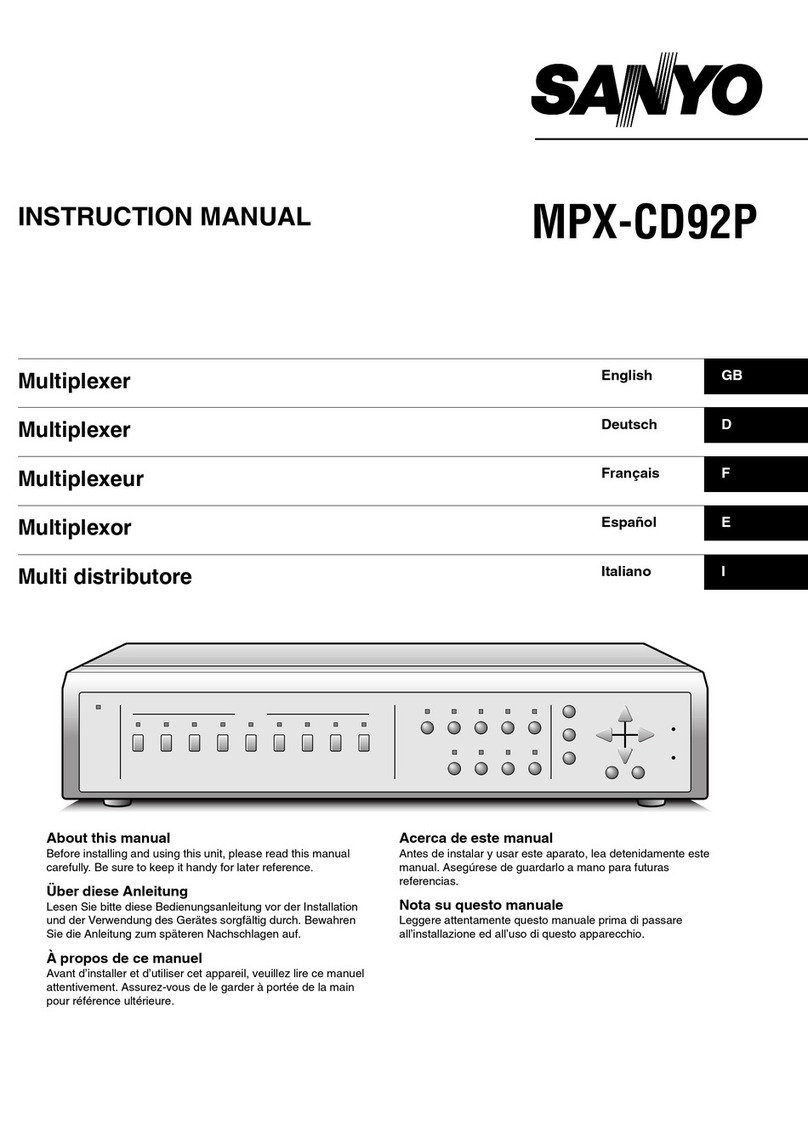
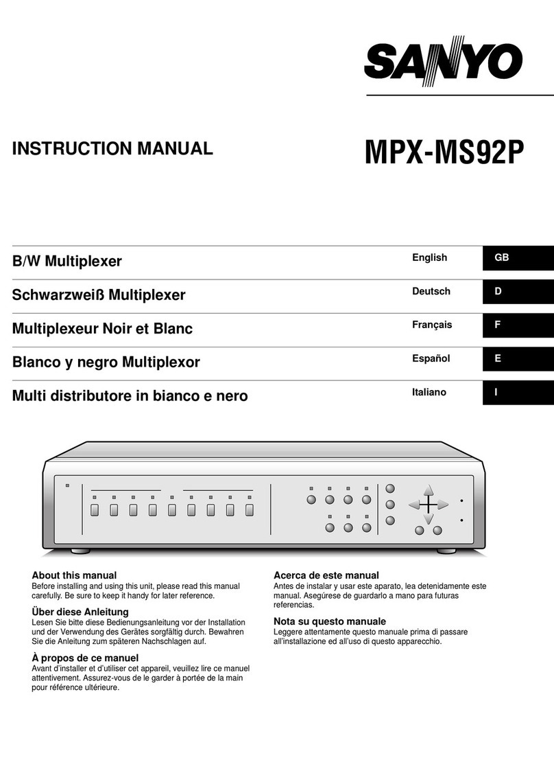
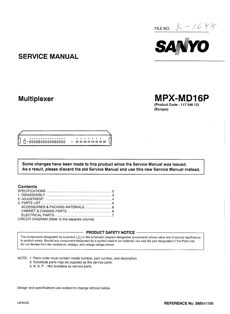
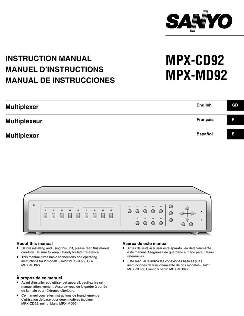
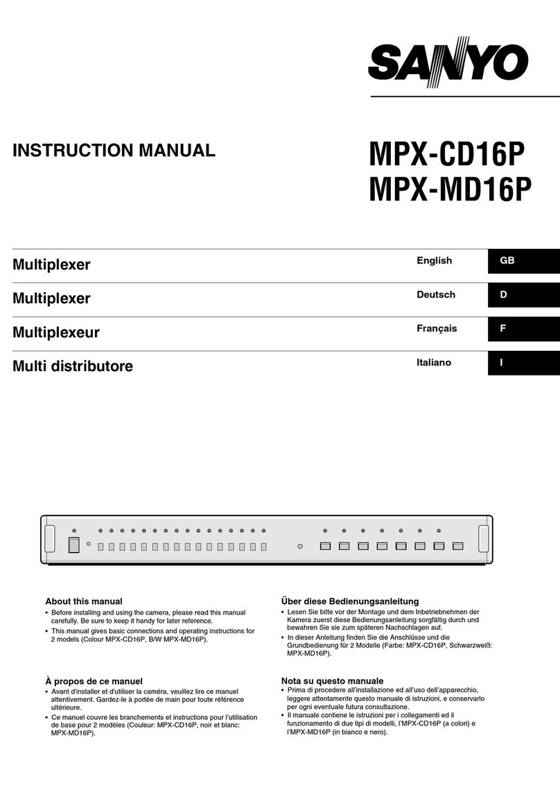
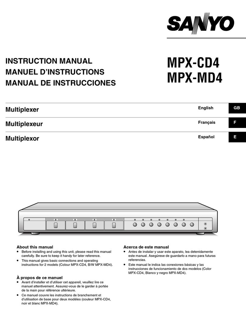
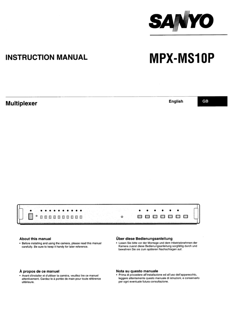
Sanyo MPX-MS10P User manual

INSTRUCTION MANUAL MPX-MS10P
Multiplexer English GB
Multiplexer Deutsch D
Multiplexeur Français F
Multi distributore Italiano I
About this manual
• Before installing and using the camera, please read this manual
carefully. Be sure to keep it handy for later reference.
Über diese Bedienungsanleitung
• Lesen Sie bitte vor der Montage und dem Inbetriebnehmen der
Kamera zuerst diese Bedienungsanleitung sorgfältig durch und
bewahren Sie sie zum späteren Nachschlagen auf.
Àpropos de ce manuel
• Avant d'installer et d'utiliser la caméra, veuillez lire ce manuel
attentivement. Gardez-le à portée de main pour toute référence
ultérieure.
Nota su questo manuale
• Prima di procedere all’installazione ed all’uso dell’apparecchio,
leggere attentamente questo manuale di istruzioni, e conservarlo
per ogni eventuale futura consultazione.
L8FF5/XE (MPX-MS10P GB) 1997. 12. 18

PRECAUTION
WARNING: TO REDUCE THE RISK OF FIRE OR
ELECTRIC SHOCK, DO NOT EXPOSE THIS
APPLIANCE TO RAIN OR OTHER MOISTURE.
To avoid electrical shock, do not open the cabinet.
Refer servicing to qualified personnel only.
If the power supply cord (AC power cord) of this
appliance is damaged, it must be replaced. Return to
a SANYO Authorised Service Centre for replacement
of the cord.
Location
For safe operation and satisfactory performance of your
Multiplexer, keep the following in mind when selecting a
place for its installation:
•Shield it from direct sunlight and keep it away from
sources of intense heat.
•Avoid dusty or humid places.
•Avoid places with insufficient ventilation for proper
heat dissipation. Do not block the ventilation holes at
the top and bottom of the Multiplexer. Do not place
the unit on a carpet because this will block the
ventilation holes.
•Install the Multiplexer in a horizontal position only.
•Avoid locations subject to strong vibrations.
•Avoid moving the Multiplexer between cold and hot
locations.
•Do not place the Multiplexer directly on top of the TV,
as this may cause playback or recording problems.
Avoiding Electrical Shock and Fire
•Do not handle the power cord with wet hands.
•Do not pull on the power cord when disconnecting it
from an AC wall outlet. Grasp it by the plug.
•If any liquid is spilled on the Multiplexer, unplug the
power cord immediately and have the unit inspected
at a factory-authorised service centre.
•Do not place anything directly on top of this
Multiplexer.
SERVICE
This unit is a precision instruments and if treated with
care, will provide years of satisfactory performance.
However, in the event of a problem, the owner is
advised not to attempt to make repairs or open the
cabinet. Servicing should always be referred to your
dealer or Sanyo Authorized Service Centre.
IMPORTANT NOTE (U. K. Only)
The wires in the mains lead are coloured according
to the following code:
Blue: Neutral
Brown: Live
If the colours of the wires in the mains lead of this
apparatus do not correspond with the colour
markings identifying the terminals in your plug,
proceed as follows:
•The wire which is coloured blue must be
connected to the terminal which is marked with
the letter Nor coloured blue or black.
•The wire which is coloured brown must be
connected to the terminal which is marked with
the letter Lor coloured brown or red.
•Do not connect either wire to the Earth terminal.
L8FF5/XE (MPX-MS10P GB) 1997. 12. 18
English 1

CONTENTS
FEATURES ....................................................................2
ACCESSORIES .............................................................2
LOCATION OF CONTROLS AND INDICATORS
Front Panel.................................................................3
Back Panel .................................................................4
CONNECTIONS.............................................................5
Assembling the D-sub 25-pin plug .............................6
BASIC FUNCTIONS ......................................................7
Switching Modes ........................................................7
Displaying and Erasing the Menus, and
Switching Between Split Screen and Full Screen ......7
Resetting the Menus ..................................................8
Resetting Operations..................................................8
Button Lock Function..................................................8
WHEN USING THE UNIT AS FRAME SWITHCER.......9
Camera Live Picture Mode (Full screen)....................9
Alarm Operation.....................................................9
Video Playback Mode...............................................10
Split Screen Viewing............................................11
Full Screen Image Viewing ..................................11
Full Screen Sequential Viewing ...........................11
x2 Zoomed In Image Viewing ..............................12
Freezed Image Viewing .......................................12
4 Divisions Split Screen Sequential Viewing........13
Alarm Operation During VCR Playback...............13
WHEN USING THE UNIT AS A MULTIVIEWER.........14
Camera Live Picture Mode (Split screen).................14
Alarm Display During Camera Live Picture
Viewing ................................................................15
ON-SCREEN MENUS..................................................16
CLOCK SETUP........................................................17
TITLE SETUP ..........................................................18
ALARM SETUP .......................................................19
CLOCK, TITLE DISPLAY........................................20
VCR SETUP.............................................................21
ALARM DATA DISPLAY.........................................23
SPECIFICATIONS .......................................................24
FEATURES
•Up to 10 images multiple field recording
Multiple field recording of the images from up to 10
cameras using only one VCR, allowing for a compact
and cost effective simple system.
•Monitoring during recording of one image or
sequential image display
•Selection of playback viewing, such as multiple
images, sequential image display, etc., or playback of
the image from the desired camera only
Selectable from the 10, 7, 4 split screen display, or
the full screen display
•Time/date and camera title displayed as necessary
Can be turned on/off for recording and/or playback
•Multiviewer function
Not only a multiplexer, the unit can be used as 10
screen splitter (with multi image recording)
ACCESSORIES
Power cord
D-sub 25-pin assembled plug
D-sub 25-pin plug components
Cover nut Locking screw E-rings
Plug plate Shielded cover A Shielded cover B
ENGLISH
L8FF5/XE (MPX-MS10P GB) 1997. 12. 18
2English
LOCATION OF CONTROLS AND
INDICATORS
Front Panel
1 3 4 56789F
G
2
1Power ON switch and indicator
2STAND BY indicator
This indicator will come on when the power cord is
connected in a live power outlet. It will go off when
the unit is turned on.
3Camera SELECT buttons and indicators
4Reset button
When this button is pressed, the unit is turned off
and the date and time are reset.
5STILL image button and indicator
6ZOOM button and indicator
7SEQUENCE select button and indicator
8MULTI (Screen splitting) button and indicator
9LIVE camera signal select button and indicator
FVCR signal select button and indicator
GMENU button
Press this button to display the main menu. Buttons
6, 7, 8, 9and Fare used for menu control (for
more information, please refer to page 16).
L8FF5/XE (MPX-MS10P GB) 1997. 12. 18
English 3

LOCATION OF CONTROLS AND INDICATORS
Back Panel
134
F2982 67
1
5
1Camera IN (Camera input) terminal
2Camera OUT (Camera output) terminal
3VCR IN (Video cassette recorder input) terminal
4VCR OUT (Video cassette recorder output) terminal
5MONITOR OUT (Monitor output) terminal
6AL OUT (Alarm output) terminal
7COM (Common) terminal
8SW IN (Switch input) terminal
9CONTROL terminal
FAC Power input
(Control terminal)
No. Signal No. Signal
1Alarm input 1 14 No operation
2Alarm input 2 15 No operation
3Alarm input 3 16 No operation
4Alarm input 4 17 GND
5Alarm input 5 18 No operation
6Alarm input 6 19 No operation
7Alarm input 7 20 No operation
8Alarm input 8 21 GND
9Alarm input 9 22 No operation
10 Alarm input 10 23 GND
11 No operation 24 Remote control 1
input
12 No operation 25 Remote control 2
input
13 No operation
By connecting the remote control pins (24 and 25) of the
CONTROL terminal to a remote control circuit, remote
controlled operation of this unit is possible. (Refer to
page 5)
L8FF5/XE (MPX-MS10P GB) 1997. 12. 18
4English

CONNECTIONS
Signal flow
: VIDEO IN
: VIDEO OUT
: CAMERA IN
Monitor (sold separately)
Video input
connector
Video cameras (sold separately)
To outlet
Video output terminal
Video input terminal
Timelapse VCR (sold separately)
Switch output terminal
COM terminal
Alarm input terminal
To pin 24 To pin 25
220 Ω
SW 1: Camera 1
220 Ω
SW 2: Camera 2
300 Ω
SW 3: Camera 3
360 Ω
SW 4: Camera 4
470 Ω
SW 5: Camera 5
680 Ω
SW 6: Camera 6
820 Ω
SW 7: Camera 7
1.2 kΩ
SW 8: Camera 8
1.8 kΩ
SW 9: Camera 9
2.2 kΩ
SW10: Camera 10
220 Ω
SW17: MENU
220 Ω
SW18: VCR
300 Ω
SW19: LIVE
360 Ω
SW20: MULTI
680 Ω
SW22:
SEQUENCE
820 Ω
SW23: ZOOM
1.2 kΩ
SW24: STILL
1.8 kΩ
SW25: POWER
To pin 21
Remote controller circuit
To pin 23
To pin 17
Alarm sensor (door bell, interphone, etc.)
To pin 10
To pin 9
To pin 8
To pin 7
To pin 6
To pin 5
To pin 4
To pin 3
To pin 2
To pin 1
470 Ω
SW21: Not used
Before making any connection, make sure the power has been turned off on all the devices.
NOTES:
•For detailed information, please refer to the manuals accompanying the other connected devices.
Make sure all the connections are correct, if not that may cause a fire and/or damages.
•With model MPX-MS10P, use black and white cameras only. If colour cameras are used, that may cause image
beat, etc.
L8FF5/XE (MPX-MS10P GB) 1997. 12. 18
English 5

CONNECTIONS
Assembling the D-sub 25-pin plug
1Preparing the cable
1Insert the cable in the cover nut (A), then
remove the cable sleeve as shown.
2Return the metallic shield mesh on the cable as
shown and cut it.
3For better shielding results, wrap about 20 mm
of copper or aluminium tape.
2Soldering the leads
Remove about 2 mm of sleeve from the end of each
leads. Apply solder on the extremity of the leads,
then solder them to the plug.
(For the pins number and signal, please refer to
page 4.)
3Installing the covers
1Insert plug plate (C) in the cover (B) slot. Check
that the shielding tape is within about 2 –3 mm
from the end of the cover (B). Push in the cover
(B) tabs.
2Align the cover (D) slot with the plug plate (C)
and push down until the clasps (E) interlock.
Tighten securely the cover nut (A) on the covers
threads.
3Insert the locking screws (F) in the holes, then
fix them by inserting the E-ring (G) between the
cover (D) and the plug plate. Bend the holder
(H) 2 or 3 times until it breaks off. Following the
same procedure, install the E-ring on the other
side.
4When the D-sub plug is assembled, connect it to
the CONTROL terminal, then affix it using the
locking screws.
A
30 mm
10 mm
2 mm
2~3 mm
C
B
D
E
C
A
F
F
G
H
D
L8FF5/XE (MPX-MS10P GB) 1997. 12. 18
6English

BASIC FUNCTIONS
Using this unit you can monitor in split screen or full screen mode, according to the received camera input mode, the
image from all the cameras connected.
Also, the image from the cameras can be recorded using a VCR, then played back by switching to VCR playback
mode. The setup of convenient functions such as the date, the time, a user set title indicating the monitoring location
or alarms, the VCR operations, etc. can be easily done using on-screen menus.
Switching Modes
When the unit is first used, it will be in camera image
viewing mode, and the camera image will be displayed
full screen on the monitor. To switch to a different
mode, follow the steps below.
Press the VCR button to select the VCR
playback mode.
If the images from the cameras have been correctly
recorded, playback will start in one of the modes
illustrated below.
Press the LIVE button to select the full
screen camera live picture viewing.
To switch to split screen viewing, please refer to
“Displaying and erasing the menus, and
switching between split screen and full screen”.
(MULTI MODE: ON) (MULTI MODE: OFF)
Press the MENU button to display the main
menu.
For setup using the menus, please refer to
“Displaying and erasing the menus, and
switching between split screen and full screen”.
Displaying and Erasing the Menus,
and Switching Between Split Screen
and Full Screen
1Press the MENU button to display the main menu.
2Press the Obutton to select “4. DISPLAY SET
OTHER”, then press the MENU button.
3Press the Obutton to select “MULTI MODE”, then
press the +(or –) button to select “ON”or “OFF”.
☞ON: For 10 divisions split screen display
To use the unit as a Multiviewer.
For the multiviewer operations, please refer to
page 14.
☞OFF: For full screen display
To use the unit as a frame switcher.
For the frame switcher operations, please refer
to page 9.
4Press the MENU button, then press the Obutton to
select “7. ENTER”and press the MENU button
again.
LIVE
MENU
L8FF5/XE (MPX-MS10P GB) 1997. 12. 18
English 7

BASIC FUNCTIONS
Resetting the Menus
The date, the time, the title indicating the monitoring
location or alarms, etc. are entered using on-screen
menus, and if the unit is moved or the installation setup
changed it is recommended to reset the menus to their
default values, before reentering the new settings.
To reset the menus to their default values, please follow
the steps below.
1Press the power ON switch to turn off the unit.
2Press the MENU button and keep it pressed down,
then press the power ON switch.
The unit will turn on in full screen camera
live viewing mode.
NOTES:
•This operation will not reset the date and time.
•Reset the menus only if it is absolutely necessary.
Resetting the menus will erase the settings previously
entered, and will also affect the internal clock.
Resetting Operations
Reset operation Reset Result
Press the Reset button. •Time, date
•Camera live picture and VCR
playback modes and indicators
selected by front panel buttons
VCR playback, Camera live
picture, Muti mode display,
Camera sequential viewing,
Zoom mode, Freezed image
mode, Camera selection
With the power to the
unit turned off, press
and hold the MENU
button, then press the
power ON switch.
Settings in the following menus
2. TITLE SET
3. ALARM SET
4. DISPLAY SET OTHER
5. VCR SET
6. ALARM DATA
Press the Reset button,
then press and hold
the MENU button, then
press the power ON
switch.
All of the reset results indicated
above. The unit will restart in the
default mode (full screen, camera
1 live viewing mode).
Button Lock Function
This unit is equipped with a function that lets you lock
the buttons to prevent any undesired operation during
camera live mode or VCR playback mode. While the
Button lock function is engaged, a buzzer will sound
when one of the buttons corresponding to each lock
mode is pressed.
☞Button lock for camera mode
Press and hold the LIVE button then press the power
ON switch.
The ON, VCR and MENU buttons will be locked, and a
buzzer will sound if they are pressed.
☞Button lock for VCR playback mode
Press and hold the VCR button then press the power
ON switch.
The ON, LIVE and MENU buttons will be locked, and a
buzzer will sound if they are pressed.
☞To cancel the Button lock function
Press and hold the LIVE or VCR button then press
the power ON switch.
MENU ON
LIVE ON
VCR
ON MENU
VCR ON
LIVE
ON MENU
L8FF5/XE (MPX-MS10P GB) 1997. 12. 18
8English

WHEN USING THE UNIT AS A FRAME
SWITCHER
Camera Live Picture Mode (Full screen surveillance)
To use the unit as a frame switcher, in the “4. DISPLAY SET OTHER”menu set “MULTI MODE”to “OFF”. (For
detailed instructions, please refer to page 7.)
When the unit is first turned on, it will be in camera live viewing mode. The LIVE indicator and the camera
indicator (1) will come on. The image from the camera connected to the camera IN 1 terminal will appear on the
monitor screen. The default setting for “MULTI MODE”is “OFF”.
The unit will memorize any mode selected when it is turned off, and will resume these modes when it is turned on
again. To switch the VCR mode, press the VCR button.
Alarm Operation
•When an input such as a door bell, an interphone, etc. connected to the
CONTROL terminal on the unit rear panel of the unit sends an alarm trigger, the
image from the alarm trigger channel will be displayed full screen and “A”will be
displayed. The camera indicator corresponding to the displayed image will flash.
When the alarm operation is finished, the unit will automatically return to the
mode preceding the alarm trigger.
•If 2 or more alarm triggers are received simultaneously, the monitor will display
sequentially, for about 1 second, all the images from the cameras corresponding
to the alarm triggers. In such a case, you can select to display only the image
from one of the cameras by pressing on the corresponding camera SELECT
button. The camera indicator corresponding to the displayed image will light.
(Only cameras corresponding to alarm triggered channels can be selected.)
Press the same camera SELECT button to return to sequential display mode.
A
A
bFor zoomed in and freezed image viewing
Press the SEQUENCE button. The image will be displayed full screen, sequentially, starting from the image
from camera 1.
The SEQUENCE indicator will light, and the MULTI indicator will go off.
NOTE:
Only the image of the cameras connected to a camera IN terminal will be displayed.
L8FF5/XE (MPX-MS10P GB) 1997. 12. 18
English 9

WHEN USING THE UNIT AS A FRAME SWITCHER
VCR Playback Mode
While viewing live camera pictures, start playback on the VCR, then press the VCR button to view the VCR
playback image on the monitor. If a camera picture is not recorded on the tape, the message “NO VIDEO”will be
displayed. To return to camera live pictures, press the LIVE button.
Also, if playing back a tape not recorded through this unit or if the recording was made
with “MULTI MODE”set to “ON”, the VCR indicator will flash and the message “NO ID”
will be displayed on the monitor screen.
NOTES:
•During playback from a timelapse/real time VCR in 12 or 24H mode the audio may not be in sync with the
viewed image.
•We recommend to use the 8H speed if using a real time VCR. Depending on the real time VCR model, there
may be a slight vertical shaking of the image or the top of the image may be slightly distorted during playback
in 24 or 40H mode.
NO VIDEO NO ID
(x2 zoom) (Freeze frame)
NO VIDEO NO VIDEO
(7 divisions) (Screens 1 to 4) (Screens 5 to 8) (Screens 9 and 10)
(10 divisions)
bFor split screen viewing (See page 11)
bFor full screen image viewing (See page 11)
bFor full screen sequential viewing (See page 11)
bFor x2 zoomed in image viewing (See page 12)
bFor freezed image viewing (See page 13)
ZS
ZS
(Freeze frame)
(x2 zoom)
10
(Freeze frame)
bFor 4 split screen sequential viewing (See page 13)
NO VIDEO NO VIDEO
L8FF5/XE (MPX-MS10P GB) 1997. 12. 18
10 English

WHEN USING THE UNIT AS A FRAME SWITCHER
Split Screen Viewing
Every time the MULTI button is pressed, one of the 5 split screen combinations is
selected. The camera indicators corresponding to the cameras displayed on-screen
will light.
NOTES:
•The unit will remember the last selected screen display combination, and when turned on
again it will select it automatically. However, the camera live picture mode will be selected,
for VCR playback you will need to press the VCR button.
•If a camera picture is not recorded on the tape, the message “NO VIDEO”will be
displayed.
Full Screen Image Viewing
From the split screen display, press a camera SELECT button and the image from
that camera will be displayed full screen.
To return to split screen display, press the MULTI button.
While viewing a full screen display, the following operations are available.
1x2 Zoomed In Image Viewing
Press the ZOOM button. The image will be zoomed in and “Z”will flash instead of the
camera number.
While in zoom mode (“Z”displayed), press the STILL button. You can then view a zoomed in
freezed image, and “ZS”will flash instead of the camera number.
To return to normal full screen mode, press the STILL button, then press the ZOOM button.
•During zoom mode, the ZOOM indicator will flash. While the zoomed in image is freezed,
the ZOOM indicator will light and the STILL indicator will flash.
2Freezed Image Viewing
Press the STILL button. You can view a freezed image and “S”will flash instead of the
camera number. To return to normal full screen mode, press the STILL button again.
•While the image is freezed, the STILL indicator will flash.
Full Screen Sequential Viewing
From the full screen display, press the SEQUENCE button to display the images
full screen, switching sequentially.
The SEQUENCE indicator will light, and the MULTI indicator will go off.
To return to split screen display, press the MULTI button.
Press the SELECT button to switch to full screen display mode.
NOTES:
•In a sequential display mode, switching will start from the screen of the lowest number
camera.
•When playing back using a timelapse VCR, use the standard speed (e.g. 3H). If using a
different playback speed, playback may not be possible.
L8FF5/XE (MPX-MS10P GB) 1997. 12. 18
English 11

WHEN USING THE UNIT AS A FRAME SWITCHER
x2 Zoomed In Image Viewing
☞Example: To watch the image from camera 8 at x2 zoom.
1Press the ZOOM button, then press the camera SELECT (8) button.
The image will be zoomed in (X2), and “Z”will flash instead of the camera number (8).
(The ZOOM indicator and the camera (8) indicator will flash.) To cancel the zoom mode,
press the ZOOM button one more time. The image can also be zoomed in when the screen
is split in 4 or 7 divisions.
2To set the zoomed in image position.
While in zoom mode (“Z”displayed), press the camera SELECT (8) button for about 3
seconds. The zoomed image will be displayed full screen and “SET”will be displayed. Using
the following buttons adjust the zoomed in image position. The zoomed in image position is
memorized by the unit.
•Button O(LIVE): To lower the image.
•Button «(VCR): To move the image towards the right.
NOTE:
About 10 seconds after having set the image position, the display will automatically return to
the original split display mode.
3To freeze a zoomed in image.
While in zoom mode (“Z”displayed), press the STILL button, then press the camera
SELECT (8) button. You can then view a zoomed in freezed image, and “ZS”will flash
instead of the camera number (8).
To return to normal zoomed in mode, press the camera SELECT (8) button again. To return
to normal viewing mode, press the STILL button, then press the ZOOM button.
Freezed Image Viewing
☞Example: To freeze the image from camera 7.
Press the STILL button, then press the camera SELECT (7) button. (The STILL
indicator and the camera (7) indicator will flash.) You can then view a freezed
image, and “S”will flash instead of the camera number (7). To return to normal
viewing mode, press the camera SELECT (7) button, then press the STILL button
again.
STILL 7
SS
L8FF5/XE (MPX-MS10P GB) 1997. 12. 18
12 English

WHEN USING THE UNIT AS A FRAME SWITCHER
4 Divisions Split Screen Sequential Viewing
From the split screen display, press the SEQUENCE button and 4 images at a time
will be displayed in a 4 divisions split screen, switching sequentially.
NO VIDEO NO VIDEO
Alarm Operation During VCR Playback
To play back a camera recording, press the VCR button. Rewind the tape in the
VCR and start playback.
When reaching a recorded alarm signal during playback, “A”will flash on the
monitor screen instead of the camera number.
NOTES:
•When reaching an alarm signal during playback, the display will automatically
switch to 10 divisions split screen display. The corresponding camera indicator
will light.
•During playback, external alarm triggers will not be received.
L8FF5/XE (MPX-MS10P GB) 1997. 12. 18
English 13

WHEN USING THE UNIT AS A MULTIVIEWER
Camera Live Picture Mode (Split screen surveillance)
To use the unit as a multiviewer, in the “4. DISPLAY SET OTHER”menu set “MULTI MODE”to “ON”. (For
detailed instructions, please refer to page 7.)
When the unit is first turned on, it will be in camera live viewing mode. The LIVE indicator, the MULTI indicator
and the camera indicators (1 –10) will come on. The monitor display will switch to 10 divisions split screen
display.
NOTE: The signal output at the MONITOR OUT terminal is also output to the VCR OUT terminal.
(x2 zoom) (Freeze frame)
NO VIDEO NO VIDEO
(7 divisions) (Screens 1 to 4) (Screens 5 to 8) (Screens 9 and 10)
(10 divisions)
bFor split screen viewing (See page 11)
bFor full screen image viewing (See page 11)
bFor full screen sequential viewing (See page 11)
bFor x2 zoomed in image viewing (See page 12)
bFor freezed image viewing (See page 13)
ZS
ZS
(Freeze frame)
(x2 zoom)
10
(Freeze frame)
bFor 4 split screen sequential viewing (See page 13)
NO VIDEO NO VIDEO
L8FF5/XE (MPX-MS10P GB) 1997. 12. 18
14 English

WHEN USING THE UNIT AS A MULTIVIEWER
Alarm Display During Camera Live Picture Viewing
When an input such as a door bell, an interphone, etc. connected to the CONTROL
terminal on the unit rear panel of the unit sends an alarm trigger, the display will
automatically switch to 10 divisions split screen display. “A”will flash on the monitor
instead of the camera number and the corresponding camera indicator will flash. To
monitor the alarm image full screen, press the SELECT button corresponding to the
flashing indicator.
The same will also happen in the following modes:
☞If in sequence display or full screen display, the display mode will automatically
switch to 10 divisions split screen display.
☞Even if the power to this unit is turned off (the unit still plugged in to a live
outlet), if the monitor is turned on, the power to this unit will be turned on
automatically and the display will switch to split screen display. After the set
alarm duration, the unit will be turned off automatically.
However, if the SELECT button is pressed to switch to full screen display, then
the unit will remain on.
NOTE: The alarm operations cannot be cancelled. Please wait until the set alarm duration
is finished.
(Setup Example) The buzzer will ring for about 30 seconds, and the image of the
corresponding camera will be zoomed in and freezed.
The ZOOM indicator, STILL indicator and corresponding camera indicators will flash. After
30 seconds, everything will return to the mode previous to the alarm trigger.
NOTE: When “MONITOR1 ZOOM”and “MONITOR1 STILL”are set to “ON”, the display
mode will not switch to full screen display.
L8FF5/XE (MPX-MS10P GB) 1997. 12. 18
English 15

ON-SCREEN MENUS
To display the main menu, or return to the main menu from a sub-menu, press the MENU button.
To select the different sub-menus, and enter the settings use the m, –, +, O, or «buttons. When a menu is
displayed, the indicators corresponding to the buttons that can be used with that particular menu will light.
Buttons functions Button m: To accept a setting.
Button –: To select in reverse order, numbers, letters, symbols. To switch
selectable settings.
Button + : To select in order, numbers, letters, symbols. To switch selectable
settings.
Button O: To move down.
Button «: To move the right.
Monitor screen
Menu screen
* If a camera is not connected
to a camera input terminal,
the message “NO VIDEO”
will appear.
CLOCK SET menu
TITLE SET menu
ALARM SET menu
DISPLAY SET menu
VCR recording SET menu
ALARM DATA screen
Title input screen
Clock display location
selection screen
NOTES:
• When displaying the menus, start
with camera signals and VCR
playback signals displayed
together in a split screen, full
screen, or sequence display.
• The menus setup screens are
displayed on the monitor
connected to the MONITOR OUT
terminal.
L8FF5/XE (MPX-MS10P GB) 1997. 12. 18
16 English

CLOCK SETUP Menu 1
☞Example: To set the clock to October 15, 1997 at 15:20 PM.
1Press the MENU button, make sure “1. CLOCK
SET”is selected, then press the MENU button
again.
2Press the +(or –) button to set the day (15), then
press the «button.
Following the same procedure, set the month (10),
the year (97), the hours (15) and the minutes (20).
For accurate clock setting, press the –button
together with a time broadcast signal or other
accurate time signal, then press the Obutton. The
seconds will start counting from 00.
3Press the +(or –) button to set the “SUMMER
TIME”to “STANDARD”or “SUMMER”, then press
the Obutton.
4Press the MENU button, then press the Obutton to
select “7. ENTER”and press the MENU button
again.
Concerning the Clock Display
The clock is displayed as indicated below.
For more information on how to display the clock, please refer to “CLOCK, TITLE DISPLAY”on page 20.
Split screen
(10 divisions)
Split screen
(4 divisions)
Full screen
NOTE:
The unit is equipped with a backup battery to maintain the clock settings. When the unit has been connected to a live
power outlet for 30 minutes or more, the battery is recharged and can maintain the clock settings for a period of up to
30 days. If the power is disconnected after having charged the battery for less than 30 minutes, that may cause a
loss of the settings.
L8FF5/XE (MPX-MS10P GB) 1997. 12. 18
English 17

TITLE SETUP Menu 2
☞Example: To set the title “GATE – – 5F”for the camera 5.
1Press the MENU button, then press the Obutton to
select “2. TITLE SET”, then press the MENU button
again.
2Press the MENU button, then press the Obutton to
select “5”and press the mbutton.
3Press the +(or –) button to set the first character
“G”, then press the «button.
Following the same procedure, set the title
“GATE – – 5F”, then press the mbutton.
Character list: A B C D....Y Z
0 1 2 3 4 5 6 7 8 9
– : . / * _
☞To enter a title for other cameras, repeat steps
2and 3.
4Press the MENU button, then press the Obutton to
select “7. ENTER”and press the MENU button
again.
Concerning the Title Display
The title is displayed as indicated below.
For more information on how to display the title, please refer to “CLOCK, TITLE DISPLAY”on page 20.
Split screen
(10 divisions)
Split screen
(4 divisions)
Full screen
NOTE:
Depending on the monitor format, the bottom titles may not appear on the screen.
L8FF5/XE (MPX-MS10P GB) 1997. 12. 18
18 English

ALARM SETUP Menu 3
1Press the MENU button, then press the Obutton to
select “3. ALARM SET”and press the MENU
button again.
2With the “ON”setting selected for “BUZZER”, press
the Obutton.
3Press the +(or –) button to select the desired
setting for “DURATION”, then press the Obutton.
Following the same procedure, select the desired
settings for “RETRIGGER”, “MONITOR1 ZOOM”,
“MONITOR1 STILL”, “VIDEO LOSS”.
(For more information on each setting, please refer
to “Alarm Settings”below.)
4Press the MENU button, then press the Obutton to
select “7. ENTER”and press the MENU button
again.
Alarm Settings
☞BUZZER
ON: The buzzer will sound when there is an alarm trigger.
OFF: The buzzer will not sound.
☞DURATION
The duration of the alarm can be selected by pressing the +
(or –) button.
10SEC, 20SEC, 30SEC, 40SEC, 50SEC, 60SEC, CC
CC: The alarm will go on as long as the alarm signal is
received (minimum 10 seconds).
☞RETRIGGER
ON: If a second alarm trigger is received during the alarm
operations for that same alarm number, it will also be
received.
OFF: During the alarm operations for an alarm number, any
alarm trigger at the same alarm number will be ignored.
The following operations are available when “MULTI
MODE” is set to “ON”
☞MONITOR1 ZOOM
•When an alarm trigger is received, the display on the
monitor will switch to split screen (10 divisions) and the
image of the camera corresponding to the alarm trigger will
be zoomed in.
•If the alarm trigger was recorded on tape, the image will not
be zoomed in.
OFF: The zoom function will not operate.
☞MONITOR1 STILL
•When an alarm trigger is received, the display on the
monitor will switch to split screen (10 divisions) and the
image of the camera corresponding to the alarm trigger will
be freezed.
•If the alarm trigger was recorded on tape, the image will not
be freezed.
OFF: The still function will not operate.
☞VIDEO LOSS
ON: An alarm is generated if there is loss of the video signal.
The display on monitor 1 will automatically switch to 10
divisions split screen, “A”will be displayed for the
camera where the loss of video signal occurred and the
ALARM DURATION will be 30 seconds. This alarm will
not be included in the ALARM DATA display.
OFF: An alarm is not generated if there is loss of the video signal.
L8FF5/XE (MPX-MS10P GB) 1997. 12. 18
English 19
Other manuals for MPX-MS10P
1
Table of contents
Other Sanyo Multiplexer manuals

Sanyo
Sanyo MPX-CD163 User manual

Sanyo
Sanyo MPX-MS10P User manual

Sanyo
Sanyo MPX-CD4P User manual

Sanyo
Sanyo MPX-MD16P User manual

Sanyo
Sanyo MPX-MS92P User manual

Sanyo
Sanyo MPX-CD16P User manual

Sanyo
Sanyo MPX-CD162 User manual

Sanyo
Sanyo MPX-CD92P User manual

Sanyo
Sanyo MPX-CD92 User manual

Sanyo
Sanyo MPX-CD4 User manual
Popular Multiplexer manuals by other brands

Pickering
Pickering 40-670C user manual

CTC Union
CTC Union FRM220-FOM04 user guide

Fujitsu
Fujitsu FLM 150 ADM Maintenance and Trouble Clearing

Broadcast Partners
Broadcast Partners DAB Plus headend aXemble manual

Lucent Technologies
Lucent Technologies Metropolis installation manual

Pickering
Pickering 40-610A user manual