manuals.online logo
Brands
  1. Home
  2. •
  3. Brands
  4. •
  5. American Dynamics
  6. •
  7. Switch
  8. •
  9. American Dynamics RJ860AP Series User manual

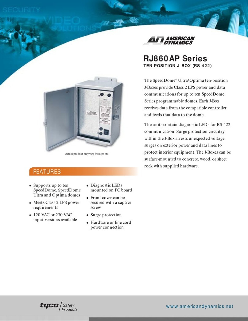
American Dynamics RJ860AP Series User manual

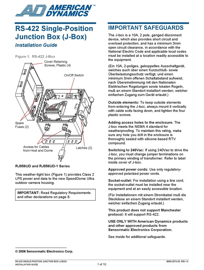
50/60HZ J-BOX 8000-0320-01, REV. E
INSTALLATION GUIDE 1 of 2
50/60Hz J-Box
Installation Guide
RJ860AP / RJ860AP1 / RJ860AP2
WARNING! Install the J-box away from
heat sources such as amplifiers,
radiators, heat registers, and stoves.
WARNING! J-box mounts to a wall only
as recommended by the manufacturer.
Mount indoors only (–10° to 50°C)!
Installation must support 90kg (200 lbs).
WARNING! Connect J-box to
unswitched, 24-hour power only.
A. Mount the J-Box to a Wall
Use mounting method A1 or A2. Use A1 when a
flexible line cord is used to power the J-box, but not
when the J-box is to be mounted in environmental
air space other than ducts and plenums. Use A2
when the J-box power is to be run through conduit,
which can be used anywhere.
A1. Wall mounting if using a line cord
1. Ensuring the 45° angle bracket is level, mount
the bracket to the wall, angle up, using hollow
wall anchors for sheetrock, concrete anchors
for block, or wood screws for plywood.
2. Attach the other 45° bracket, angle down, to the
enclosure back using two 6.4mm (1/4in) hex
head bolts through the top mounting holes of
the enclosure. Secure bolts with washers, lock
washers, and nuts.
3. Attach two rubber bumpers to the enclosure
back using the lower enclosure mounting holes,
and #10 bolts, lock washers, and nuts, which
enter holes from the inside.
4. Attach the enclosure to wall, ensuring dimple on
one bracket seats in the hole of the other.
5. Remove knockouts as needed for cable access.
© 2004 Sensormatic Electronics Corp.
A2. Wall mounting if using conduit
CAUTION: When using conduit, a 10A, 2 pole,
ganged disconnect device, which also provides
short circuit and overload protection, and has a
minimum 3mm open circuit clearance, in
accordance with the National Electric Code and
applicable local codes must be installed at a location
readily accessible to the equipment.
1. Remove four #10 screws that secure the plate
assembly to the enclosure and remove the
plate assembly.
2. Securely mount the enclosure to the wall using
hollow wall anchors for sheetrock, concrete
anchors for block, or wood screws for plywood.
3. Punch out knockouts to provide necessary
access and reinstall the plate in the enclosure
using #10 screws.
B. Connect Composite & Video Cables
1. Route composite cables through the large
knockouts and plug them into the Jones
connector. If not using conduit, line the large
knockout holes with plastic edge guard from the
install kit.
2. Route trunk run video cables into the J-box,
install female BNC connectors, and connect
them to the composite video cables.
3. Remove the video channel cover and install the
connector portion of joined video cables in the
slots (one cable per slot).
4. Replace the video channel cover.
50/60HZ J-BOX 8000-0320-01, REV. E
INSTALLATION GUIDE 2 of 2
C. Connect the 4-Conductor Data Cable
1. Route a 4-conductor cable into the J-box, strip
four wires to expose 1cm (3/8in) of wire, and
cut the drain wire back to the outer sheath.
2. Insert wires in holes in the spring-loaded
terminal block by pushing the orange buttons
beside the holes. Note the function label on the
PC board beside each button.
D. Connect Power to J-Box
CAUTION: The J-Box must connect to a branch
circuit controlled by a disconnect device, such as a
circuit breaker, with at least a 3mm disconnect
separation. Recommended capacity of the
disconnect device branch circuit is 10A, and the
device must be readily accessible. If these
conditions cannot be met, install a disconnect
device (with at least 3mm separation) in series with
the J-Box, and between the branch and the J-Box.
If using conduit
1. Remove the cover over terminal block TB3.
2. Route 50 or 60Hz electrical power into the J-
box through the small knockout and connect it
to TB3 (see table opposite).
Note: Steps 3–5 for RJ860AP1 only. Otherwise,
skip to step 6.
3. An 18cm (7in) ground wire from TB3 is attached
to a grounding post on the enclosure. Remove
the washer and nut from the grounding post
and remove the ground wire terminal.
4. Wrap the branch circuit ground wire completely
around the grounding post and secure using the
washer and nut.
5. Reattach the TB3 ground wire terminal to the
grounding post and secure using the extra
washer and nut supplied.
6. Reattach the cover over TB3.
If using line cord
CAUTION: Use only polarized plug/cord sets; non-
polarized plugs invalidate regulatory approvals!
Cord type:
North America: The cord must be type SJT, with
minimum conductor size of 18AWG and fitted with a
connector rated at 10A, 125V. The cord anchor
accepts cords with a 5–9mm outer diameter.
EU: The cord must be type H05 VV-F or H05 VV
H2-F, with minimum conductor size of .75mm2 and
fitted with a connector rated at 10A. The cord
anchor accepts cords with a 5–9mm outer diameter.
1. Remove the cover over terminal block TB3.
2. Place the anchor for the power cord in the
knockout and pass the power cord through the
anchor.
3. Remove the outer sheath from the power cord
and cut the three wires inside to length with the
ground wire being the longest so it will break
last if the anchor fails.
4. Connect the line and neutral leads to TB3 (see
table below). Tie wrap these leads close to
TB3.
RJ860AP1 only. An 18cm (7in) ground wire
from TB3 is attached to a grounding post on the
enclosure. Remove the washer and nut from
the grounding post and remove the ground wire
from the post.
RJ860AP and RJ860AP2 only. Install a ring
terminal on the power cord’s ground wire. Place
this terminal over the grounding post and
secure using the washer and nut.
RJ860AP1 only. Reattach the TB3 ground wire
terminal to the grounding post and secure using
the extra washer and nut supplied.
5. Tighten the anchor to secure the power cord.
6. Reattach the cover over TB3.
60Hz Line Cord 60Hz Conduit
TB3-1 Hot (Brown) Hot
TB3-2 Neutral (Blue) Neutral
Ground Lug Ground (Green) Ground
50Hz Line Cord 50Hz Conduit
TB3-1 L (Hot) L (Hot)
TB3-2 N (Neutral) N (Neutral)
Ground Lug Ground
(Green/Yellow or
Copper)
Ground
Other manuals for RJ860AP Series

2

This manual suits for next models

2

Other American Dynamics Switch manuals

American Dynamics MegaPower AD1024HS User manual

American Dynamics

American Dynamics MegaPower AD1024HS User manual

American Dynamics RJ1SNUD Series User manual

American Dynamics

American Dynamics RJ1SNUD Series User manual

American Dynamics AD168 User manual

American Dynamics

American Dynamics AD168 User manual

American Dynamics AD1476-C User manual

American Dynamics

American Dynamics AD1476-C User manual

American Dynamics AD1985A User manual

American Dynamics

American Dynamics AD1985A User manual

American Dynamics AD2031 User manual

American Dynamics

American Dynamics AD2031 User manual

American Dynamics SensorNet RJ6SN User manual

American Dynamics

American Dynamics SensorNet RJ6SN User manual

American Dynamics AD2033 User manual

American Dynamics

American Dynamics AD2033 User manual

American Dynamics RJ1SNUD Series User manual

American Dynamics

American Dynamics RJ1SNUD Series User manual

American Dynamics ADQUAD47 User manual

American Dynamics

American Dynamics ADQUAD47 User manual

American Dynamics AD1416 User manual

American Dynamics

American Dynamics AD1416 User manual

American Dynamics AD168 User manual

American Dynamics

American Dynamics AD168 User manual

American Dynamics RJ856UD Series User manual

American Dynamics

American Dynamics RJ856UD Series User manual

American Dynamics RJ860AP Series User manual

American Dynamics

American Dynamics RJ860AP Series User manual

American Dynamics VM2000 User manual

American Dynamics

American Dynamics VM2000 User manual

Popular Switch manuals by other brands

AMT FS-2MIDI user manual

AMT

AMT FS-2MIDI user manual

Sony ESBK-7052 operating instructions

Sony

Sony ESBK-7052 operating instructions

serverLink SL-202-DV Quick installation guide

serverLink

serverLink SL-202-DV Quick installation guide

Steren ALA-003 instruction manual

Steren

Steren ALA-003 instruction manual

ADDER ADDERView CCS-MV4228 user guide

ADDER

ADDER ADDERView CCS-MV4228 user guide

Extron electronics YCS SW2 A user guide

Extron electronics

Extron electronics YCS SW2 A user guide

Siemens SIRIUS 3TY7561-1UA00 operating instructions

Siemens

Siemens SIRIUS 3TY7561-1UA00 operating instructions

D-Link Dis-200G Series Cli reference guide

D-Link

D-Link Dis-200G Series Cli reference guide

Matrix Tippkemper IRS I-OFX Series Original operating manual

Matrix

Matrix Tippkemper IRS I-OFX Series Original operating manual

CTC Union FS-802GS-8PH Quick installation guide

CTC Union

CTC Union FS-802GS-8PH Quick installation guide

HP ProCurve 5300xl Management guide

HP

HP ProCurve 5300xl Management guide

ATEN Slideaway CL1008 user manual

ATEN

ATEN Slideaway CL1008 user manual

Kramer VS-1211 user manual

Kramer

Kramer VS-1211 user manual

IBM TotalStorage 3534-F08 installation guide

IBM

IBM TotalStorage 3534-F08 installation guide

Linkskey Prima LKV-9304 Quick installation guide

Linkskey

Linkskey Prima LKV-9304 Quick installation guide

Sonoff DIY MINI user manual

Sonoff

Sonoff DIY MINI user manual

Citel TVA-A Integration guide

Citel

Citel TVA-A Integration guide

H3C S12500-X Configuration guide

H3C

H3C S12500-X Configuration guide

manuals.online logo
manuals.online logoBrands
  • About & Mission
  • Contact us
  • Privacy Policy
  • Terms and Conditions

Copyright 2025 Manuals.Online. All Rights Reserved.