American Eagle SHD 30 User manual

American Eagle, Inc.
740 N. State Street
PO Box 169
Garner, IA 50438
800-392-3015
Fax: 641-923-9099
www.americaneagleacc.com
odel 200 Compressor
odel SUH 30 Compressor
odel SHD 30 Compressor
anual Part No. 40982
Last Revision: 07/08/13
Subject to Change without Notification.
© 2013 American Eagle
Safety, Installation, aintenance, and Operation
OWNER’SANUAL

Class 2 Compressor anual Revisions
Date of Revision Description of RevisionSection Revised

i
Table of Contents
Int oduction . . . . . . . . . . . . . . . . . . . . . . . . . . . . . . . . . . . . . . .ii
Safety . . . . . . . . . . . . . . . . . . . . . . . . . . . . . . . . . . . . . . . . . . . .1
Specifications . . . . . . . . . . . . . . . . . . . . . . . . . . . . . . . . . . . . .2
General Specifications . . . . . . . . . . . . . . . . . . . . . . . . . . . . . .2
Compressor System Description . . . . . . . . . . . . . . . . . . . . . .2
SHD-30 Drive System Description . . . . . . . . . . . . . . . . . . . . . .2
Operation . . . . . . . . . . . . . . . . . . . . . . . . . . . . . . . . . . . . . . . .3
General Operation Notes . . . . . . . . . . . . . . . . . . . . . . . . . . .3
SHD-30 Operation Notes . . . . . . . . . . . . . . . . . . . . . . . . . . . . .3
aintenance . . . . . . . . . . . . . . . . . . . . . . . . . . . . . . . . . . . . . .4
Installation . . . . . . . . . . . . . . . . . . . . . . . . . . . . . . . . . . . . . . . .5
Compressor Installation . . . . . . . . . . . . . . . . . . . . . . . . . . . . . .5
SHD-30 Installation . . . . . . . . . . . . . . . . . . . . . . . . . . . . . . . . . .6
Pressure Setting Instructions . . . . . . . . . . . . . . . . . . . . . . . . . .7
Assembly Drawings . . . . . . . . . . . . . . . . . . . . . . . . . . . . . . . .8
Crankcase Group (Tapered Shaft) . . . . . . . . . . . . . . . . . . . .8
Crankcase Group (Straight Shaft) . . . . . . . . . . . . . . . . . . . . .9
Cylinder Group . . . . . . . . . . . . . . . . . . . . . . . . . . . . . . . . . . .10
Head Group . . . . . . . . . . . . . . . . . . . . . . . . . . . . . . . . . . . . . .11
Head Options . . . . . . . . . . . . . . . . . . . . . . . . . . . . . . . . . . . . .12
Optional Head Unloader . . . . . . . . . . . . . . . . . . . . . . . . . . .13
Flywheel Options . . . . . . . . . . . . . . . . . . . . . . . . . . . . . . . . . .14
Clutch Options . . . . . . . . . . . . . . . . . . . . . . . . . . . . . . . . . . . .15
SUH-30 Compressor Assembly . . . . . . . . . . . . . . . . . . . . . . .16
SHD-30 Compressor Assembly . . . . . . . . . . . . . . . . . . . . . . .17
Hydraulics/Electrical . . . . . . . . . . . . . . . . . . . . . . . . . . . . . .18
SHD-30 Control Kit . . . . . . . . . . . . . . . . . . . . . . . . . . . . . . . . .18
Typical Hydraulic Circuit for Tandum (Two Part) Pump
with ultiple Components . . . . . . . . . . . . . . . . . . . . . . . . . .19
Typical Hydraulic Circuit for Single Stage Pump
with ultiple Components . . . . . . . . . . . . . . . . . . . . . . . . . .19
Typical Hydraulic Circuit for Compressor
with Auxiliary Cooler . . . . . . . . . . . . . . . . . . . . . . . . . . . . . . .20
Replacement Parts . . . . . . . . . . . . . . . . . . . . . . . . . . . . . . . .21
Troubleshooting . . . . . . . . . . . . . . . . . . . . . . . . . . . . . . . . . .22
General Troubleshooting . . . . . . . . . . . . . . . . . . . . . . . . . . .22
SHD-30 Troubleshooting . . . . . . . . . . . . . . . . . . . . . . . . . . . .23
Wa anty Info mation . . . . . . . . . . . . . . . . . . . . . . . . . . . . . .26

ii Class 2 Comp esso Owne ’s Manual
American Eagle Compressors are designed
to provide safe and dependable service for
a variety of operations. With proper use and
maintenance, American Eagle Compressors
will operate at peak performance for many
years.
This manual contains information vital to the
safe use and efficient operation of this unit.
Following the information provided within this
manual can ensure the longevity of the
compressor. Carefully read and study the
operator’s manual before using the unit.
Failure to adhere to the instructions could
result in property damage or even serious
bodily injury to the operator or others close
to the compressor.
A copy of this manual is provided with every
compressor and shall remain with the
compressor at all times. Information
contained within this manual does not cover
all maintenance, operating, or repair
instructions pertinent to all possible situations.
This manual is not binding.
American Eagle reserves the right to
change, at any time, any or all of the items,
Introduction
components, and parts deemed necessary
for product improvement or
commercial/production purposes. This right
is kept with no requirement or obligation for
immediate mandatory updating of this
manual.
This product manual is not intended as a
training manual for beginners or unskilled
operators. This manual offers guidelines for
correct and safe usage of the compressor,
maintenance, and troubleshooting. If more
information is required or technical
assistance is needed, please contact AE
Technical Support.
Some sections of this manual contain
information pertaining to all American Eagle
manufactured compressors and may or may
not apply to your specific model.
If this manual becomes damaged,
misplaced, or unreadable at any point, or if
you feel that any part of this manual is
unclear or incorrect, please contact AE
Technical Support at 800-321-3741 or email
Technical Questions, and Information [email protected]
Order Parts [email protected]
Warranty Information [email protected]
For Technical Questions, Information, Parts, or Warranty, Call Toll-Free at
800-321-3741
Hours: onday - Friday, 8:00 a.m. - 5:00 p.m. CST
Or email at the following addresses:

Safety 1
Safety
This manual contains vital information for the safe use and efficient
operation of this unit. Carefully read the operators manual before starting
the unit. Failure to adhere to the instructions could result in serious bodily
injury or property damage.
Every American Eagle Compressor will
provide safe and dependable service if
operated according to instructions. Read
and understand the safety precautions
given in this manual and on the decals
attached to the shields. Failure to do so can
result in personal injury or equipment
damage.
Operators and maintenance personnel must
always comply with the safety precautions.
These precautions are given here for your
safety. Review them carefully before
operating the compressor and before
performing maintenance or repairs.
Supervising personnel should develop
additional precautions relating to the
specific work area and local safety
regulations.
Precautions
Always wear safety equipment such as
goggles, ear plugs and head protection at
all times when operating the compressor.
Do not inspect or clean the compressor
while the hydraulic power source is
connected. Accidental engagement of the
tool can cause serious injury.
Before performing any maintenance on the
compressor, place a warning tag on the
hydraulic power source or disconnect the
hoses from the compressor motor to prevent
accidental startup of the compressor.
Always connect hoses to the compressor
before energizing the hydraulic power
source. Be sure all hose connections are
tight, both air and hydraulic.
Establish a training program for all operators
to ensure safe operation.
Do not operate the compressor unless
thoroughly trained or under the supervision
of an instructor.
Do not operate the compressor if it is
damaged, improperly adjusted or not
completely or properly assembled.
Never operate the compressor with any of
the guards removed.
Do not attempt to adjust or disable the
compressors air pressure relief valve. This
valve limits the air pressure to 150 PSI.
The surface of the air compressor and the
plumbing between the compressor and the
cooler may reach temperatures above 150
degrees. Touching these surfaces during
operation can cause burns.
The air taken in by the air compressor must
be free of flammable fumes and vapors.
Compressor speed should not exceed 1300
RP .
Use and operate this air compressor only in
full compliance with all pertinent O.S.H.A.
requirements and all Federal, State and
Local codes or requirements.

2Class 2 Comp esso Owne ’s Manual
Specifications
• odel: 200
• Weight: 60 lbs (SHD-30: 165 lbs)
• Delivery: 13 CF @ 100 PSI
• aximum Working Pressure: 150 PSI
• Dimensions: (SHD-30) 26”L x 14.5”W x 17”H
• Electrical: 12 VDC
• Oil Capacity: 24 Ounces
• Cylinders: Two Cylinder(Single Stage)
• aximum Compressor Speed: 1300 RP
• 7 GP Hydraulic System • 1800 PSI System Pressure
• 2500 PSI Pressure Relief Setting • 12 VDC Solenoid Control Valve
• All Steel Plumbing W/ JIC Fittings • Oil Cooler
• 12 Volt Cooler Fan • 6061 Aluminum anifold
• Direct Drive Coupling • Air Pressure Control Valve
SHD-30 Drive System Description
• Cast Iron Crankcase Casting • Heavy Duty Journal Bushings
• Cast Iron Cylinder Head • Heavy Ductile Iron Crankshaft
• High Temperature Precision Pistons • icro-honed Connecting Rods
• Stainless Steel Reed Valves • Pressure Lubricated System
Compressor System Description
General Specifications

Ope ation 3
Operation
General Operation Notes
Before Start-Up
Check the oil level in the compressor with the dipstick on the unit. If oil is needed, use
American Eagle synthetic compressor oil (P/N C0087) or an equivalent 10W20 synthetic oil.
Note: There may be oil left in the crankcase from the factory bench test. Overfilling may
cause the compressor to back blow oil. Always check the oil level and fill to the
designated marking on the dipstick before putting the unit into service.
Check the air intake filters on each head to make certain that they are clean and
unobstructed. Dirty air filters are a possible cause of reduced air output.
Each compressor is bench tested under load at the factory to ensure proper break-in and
operation. While it is not necessary to follow any break-in procedure, the following checks
should be made before putting the unit into service and periodically during use.
If adjustment is necessary for cable operated speed controls, loosen the jam nut on the
cable end, make the adjustment and retighten the jam nut.
For electronic operated speed controls, adjust speed adjustment screw as needed to set
RP .
For setting engine RP through the chassis EC , contact local chassis dealer.
When the air pressure falls below 120 PSI, the 12 volt electric solenoid opens allowing
hydraulic oil to flow to the hydraulic drive motor then back to the manifold and through
the oil cooler assembly. Once the air pressure reaches 150 PSI the solenoid closes
shutting off the oil flow to the motor and diverts the oil to the oil cooler.
With the compressor engaged, the main cooling system, which consists of an oil cooler,
electric fan motor and fan continually runs drawing ambient air through the cooler fins
and across the fan assembly discharging heated air past the compressor and out the
cover assembly.
SHD-30 Operation Notes
To use the compressor, start the engine and engage the hydraulic system with the
compressor toggle switch. Through the hydraulic valve manifold, the system will now
function automatically. Once engaged, adjust the engine speed control to ensure that the
compressor speed does not exceed 1300 RP under load.

4Class 2 Comp esso Owne ’s Manual
aintenance
The following table is a list of routine maintenance items, including service intervals. Service
intervals are listed as hours, days, or weeks, whichever occurs first. American Eagle
recommends that these service intervals be followed.
Under normal operating conditions, oil changes are required every 3 months. When operating in a
dirty environment, change the oil more frequently as your particular operating condition dictates.
General preventative maintenance includes maintaining proper fluid level in both systems and the
general cleanliness of the equipment. Proper fluids according to the specifications are required.
USE AE SYNTHETIC CO PRESSOR OIL (OR 10W20 EQUIVALENT) P/N C0087.
CO PRESSOR CRANKCASE CAPACITY IS 24 OUNCES.
Service Intervals
aintenance operation Daily Weekly onthly Hourly
Drain air tanks
Check crankcase oil level
Check fittings and airlines
Check hydraulic fluid level
Inspect and clean air intake filters
Clean and operate safety valves
Clean cooling fins on radiator
Inspect check valve
Inspect and clean compressor valves 6
Replace hydraulic filter 6
Replace air filters 3
Tighten all fittings and fasteners 3
Check all electrical connections 3
Check compressor reed valves 250
Inspect and clean air check valve 250
CHANGE CRANKCASE OIL (see footnote below)

Installation 5
Installation
Compressor Installation
Component Installation
This section pertains to the installation of the air compressor, PTO, pump and
other related items. The instructions are intended as a guide to assist you with
particular installation. These instructions will provide only general information.
Torque and Procedure Chart
Head Assembly
Torque Value: 34 FT. LBS.
Procedure: Assemble head on the cylinder with head bolts
started only, not tight. Working in the pattern shown, torque
three times, increasing the torque each time as follows:
First Torque: 10 FT. LBS.
Second Torque: 20 FT. LBS.
Third Torque: 34 FT. LBS.
After five hours of use re-torque bolts to 34 ft-lbs.
Cylinder Assembly
Torque Value: 20 FT. LBS.
Procedure: After assembling cylinder over pistons and setting into place, tighten (6) cap
screws finger tight. In a criss-cross pattern, tighten bolts evenly so all bolts are hand snug.
Again in a criss-cross pattern torque each bolt to 20 ft-lbs., checking each bolt twice.
After five hours of use, re-torque bolts to 20 ft-lbs.
Connecting Rod Assembly
Torque Value: 18 FT. LBS.
Procedure: Assemble rod onto the crankshaft taking care to align the machined
surfaces together and tighten cap screws finger tight. Tighten bolts until hand tight and
torque to 18 ft-lbs. Check twice the torque reading before final assembly of the
cylinders.
12
34
56

6Class 2 Comp esso Owne ’s Manual
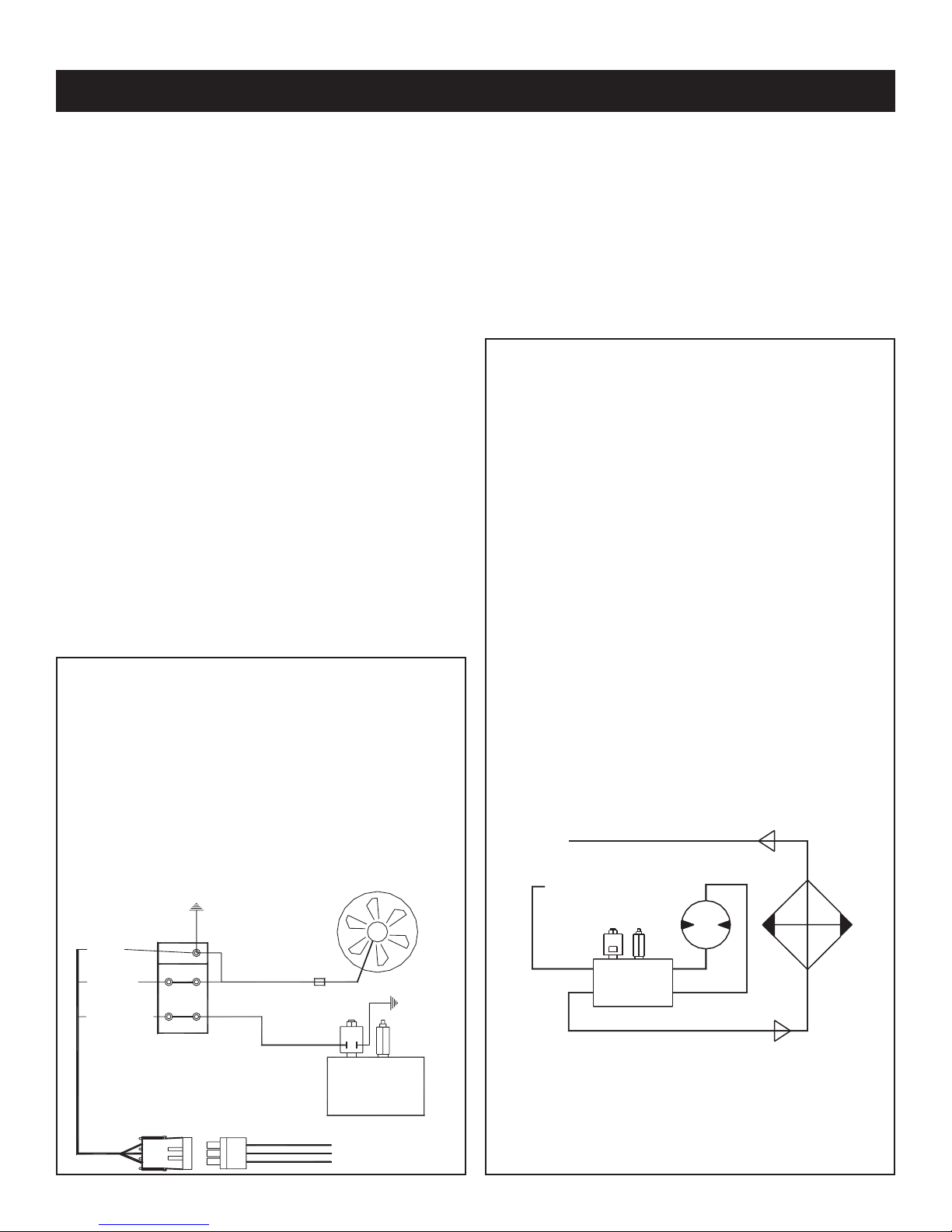
Return Line
Pressure
Line
FAN
GND
CPRSR
SPD CTRL
PRESSURE
SWITCH
LINE
MOTOR
HYDRAULIC
MANIFOLD
COMPRESSOR (12V INPUT)
GROUND
SPEED CONTROL
C
B
A
C
B
A
SHD-30 Installation
Pump Assembly:
The pump assembly may either be installed directly
on the PTO or as an optional method, may be
driven by a driveline from the PTO. Pump
manufacturers provide specific installation
information for their products and should be
consulted if questions arise.
PTO Assembly:
Check with the PTO manufactures representative
for specific instructions regarding your particular
make, model, and year of vehicle. As some trucks
may require modification of the transmission cross
member and the exhaust system, the
manufacturer’s instructions should be followed to
insure proper installation of the PTO.
Compressor Assembly:
Prepare the mounting location of the compressor
by locating and drilling four (4) holes, 7/16”
diameter as per the mounting pattern of the air
compressor base. Using four (4) 3/8” x 1.25 GR-5
cap screws, 3/8” flat washdrs, and 3/8” nyloc nuts,
secure the compressor in place. The compressor is
air cooled, and must have a clean supply of
cooling air to the fan with minimum restrictions.
Adequate space must be provided for proper
circulation of air.
Electrical Connections:
From the air pressure switch there are two (2) wires,
red and black, running to the outside of the
compressor housing. Connect the black wire to the
vehicle frame or other suitable ground. ount a
single throw toggle switch in a convenient location
and connect the red wire from the compressor to
this switch. Connect the other switch terminal to a
fuse holder and then to a 12-volt power supply. A
third wire is required from the air compressor switch
when connecting the speed control into the
system.
Electric speed control:
An optional electric or electronic speed control
must be used to maintain proper operating speed
of the air compressor. The engine speed control will
automatically increase from idle to preset speed
when engaged and decrease when disengaged.
The electric cable pull speed control (American
Eagle P/N 25740) is used on most gasoline engines.
The electronic speed controls are used only on Ford
7.3 and 6.0L diesel engines. Proper installation
instructions are provided with each system.
Hydraulic System:
The hydraulic system consists of the pump, oil
reservoir, filters and hoses. Installed on the
compressor is a valve block assembly that controls
the flow to the hydraulic motor. To this block, a 1/2”
high-pressure hose must be attached. This hose
comes from the hydraulic pumps pressure side. A
3/4” minimum low-pressure return line is connected
to the oil cooler outlet and is routed to the oil
reservoir. American Eagle recommends a sufficient
sized reservoir be provided which includes the
proper suction and return filters. The cooler on the
compressor is designed and sized to cool the air
compressor efficiently. An auxiliary oil cooler is
required when additional hydraulically operated
equipment are added to the hydraulic system.
Pressure on the return line exceeding 200 PSI can
and will cause damage to the filter, cooler, and
components of the compressor hydraulic system.

Installation 7
Pressure Setting Instructions
Pressure Setting Instructions:
1. Always set the kick out pressure setting first. 145 psi minimum/150 psi maximum.
2. After kick out pressure is set, adjust the kick on screw setting at 115 psi minimum/120
psi maximum.
3. Cycle compressor to verify correct settings.
4. For questions about this procedure, please contact Stellar Customer Service.
Kick On (Step 2)
Pressure Setting
Adjustment
Screw
(115-120 psi)
Kick Out (Step 1)
Pressure Setting
Adjustment
Screw
(145-150 psi)
Note: Turning adjustment screws clockwise
increases psi settings. Turning adjustment screws
counterclockwise decreased psi settings.
+
+
-
-

8Class 2 Comp esso Owne ’s Manual
Crankcase Group (Tapered Shaft)
Assembly Drawings
17
16
14
15
13
11
12
32
29
31
30
10
9
8
1
5
6
33
4
3
2
25
24
20
22
23
21
26
27
28
18
19
7
34
35
ITEM
PART
DESCRIPTION
QTY.
ITEM
PART
DESCRIPTION
QTY.
1 5791
CRANKCASE 200 O/S
1
2 5788
PLUG OIL INTAKE FILTER-200
1
3 5787
O'RING OIL INTAKE FILTER-200
1
4 5785
TUBE OIL INTAKE .25ODX3.00
1
5 5784
SCREEN OIL INTAKE FILTER-200
1
6 5790
PLUG 0.25 NPT SQ HD
1
7 5811
GASKET BEARING CARRIER-200 (.015)
5
8
C1163
BEARING CUP (LM67010)
1
9
C6268
BEARING SEAL V480
1
10 20683
BREATHER CPRSR .38NPT B38 200
1
11 5782
CRANKSHAFT 200 TAPER O/S
1
12
C0856
BEARING CONE LM67048
1
13
C0855
BEARING CONE
1
14 5820
OIL PUMP DRIVE SLEEVE V480/V360/200
1
15 5817
ROLL PIN 0.19X.50
1
16
C0060
SPRING OIL PUMP
1
17
C0059
OIL PUMP TRANSFER BUSHING
1
18 6835
BEARING CARRIER 200
1
19
C1164
BEARING CUP (L44610)
1
20
C0054
PORT PLATE COVER GASKET (SMALL)
1
21
C6275
PORT PLATE GASKET
1
22
C0052
PORT PLATE MACHINED
1
23 22209
ROLL PIN 0.19X.63
1
24 22626
PORT PLATE COVER
1
25 0485
CAP SCR 0.31-18X1.25 HHGR5
4
26
C0050
OIL PUMP
1
27 6034
SCREW 0.31-18X1.00 SHC
4
28 5819
GAUGE OIL PSI 1.5
1
29 23050
DIPSTICK BODY (200)
1
30 23049
DIPSTICK ROD (200)
1
31
C0041
O'RING-112
1
32 22686
HANDLE DIPSTICK OIL CHECK V480
1
33
C6273
SNAP RING PISTON PIN N5000-62
1
34
C4703
KEY WOODRUFF 5/32 X 3/4 #8
1
35 50389
WASHER 0.885X1.115X0.064 COPPER
1

Assembly D awings 9
Crankcase Group (Straight Shaft)
17
15
14
16
11
8
12
2
5
4
6
33
27
24
23
22
20
21
19
18
25
32
10
13
3
26
9
1
7
28
30
29
31
34
35
ITEM
PART
DESCRIPTION
QTY.
ITEM
PART
DESCRIPTION
QTY.
1 5791
CRANKCASE 200 O/S
1
2 5788
PLUG OIL INTAKE FILTER-200
1
3 5811
GASKET BEARING CARRIER-200 (.015)
5
45785
TUBE OIL INTAKE .25ODX3.00
1
55787
O'RING OIL INTAKE FILTER-200
1
6 5784
SCREEN OIL INTAKE FILTER-200
1
7
C6268
BEARING SEAL V480
1
8 22836
CRANKSHAFT 200 S O/S
1
9
C1163
BEARING CUP (LM67010)
1
10
C1164
BEARING CUP (L44610)
1
11
C0855
BEARING CONE
1
12
C0856
BEARING CONE LM67048
1
13 6835
BEARING CARRIER 200
1
14 5820
OIL PUMP DRIVE SLEEVE V480/V360/200
1
15
C0060
SPRING OIL PUMP
1
16 5817
ROLL PIN 0.19X.50
1
17
C0059
OIL PUMP TRANSFER BUSHING
1
18
C0050
OIL PUMP
1
19
C6275
PORT PLATE GASKET
1
20
C0052
PORT PLATE MACHINED
1
21 22209
ROLL PIN 0.19X.63
1
22
C0054
PORT PLATE COVER GASKET (SMALL)
1
23 22626 1
24 0485
CAP SCR 0.31-18X1.25 HHGR5
4
25 6034
SCREW 0.31-18X1.00 SHC
4
26 20683
BREATHER CPRSR .38NPT B38 200
1
27 5790
PLUG 0.25 NPT SQ HD
1
28 23049
DIPSTICK ROD (200)
1
29 23050
DIPSTICK BODY (200)
1
30
C0041
O'RING-112
1
31 22686
HANDLE DIPSTICK OIL CHECK V480
1
32 5819
GAUGE OIL PSI 1.5
1
33
C6273
SNAP RING PISTON PIN N5000-62
1
34 23047 1
35 50389
WASHER 0.885X1.115X0.064 COPPER
1

10 Class 2 Comp esso Owne ’s Manual
Cylinder Group
6
5
4
2
3
5
12
9
8
7
10
11
1
12
.YTQNOITPIRCSEDTRAPMETI
2TEKSAGREDNILYC7400C1
2C6364 CONNECTING ROD 200/V480 O/S 2
2084V/002NOTSIP76753
2084V/002NIPNOTSIP7636C4
5C6273 SNAP RING PISTON PIN N5000-62 4
6C6360 CYLINDER V480 FINISHED O/S 1
6KCOL13.0REHSAW22507
8C0922 CAP SCR 0.31-18X1.00 HHGR5 6
95827 RING OIL V480/200 FLEX DIVIDER 2
10 32931 RING SCRAPER V480/200 H#48638 2
11 32930 RING CPRSN V480/200 BARREL H#38347 2
12 36368 RING OIL V480/200 RING RAIL 4
CYLINDER GROUP

Assembly D awings 11
Head Group
5
3
4
2
1
31
21
11
01
8
7
9
6
41
.YTQNOITPIRCSEDTRAPMETI
1S/O002C/ADAEH83751
4TLOBDAEHHS57.1X61-83.0RCSPAC6851C2
1LTSTLOBDHREHSAW0400C3
1)SSARB(TLOBDHGNOLREHSAW82854
2TLOBDAEHHS00.3X61-83.0RCSPAC2851C5
1NEERCSRETLIF7920C6
1MAOFRETLIF6920C7
1RENIATERRETLIF4920C8
1MAOFRETLIF5170C9
3FN88.0X23-01#WERCS0030C01
1084/002ETALPEVLAVTEKSAG7880D11
1S/OMSABUSETALPEVLAV3014221
1084/063/032/341DAEHTEKSAG0130C31
3RSRPCRATS01#REHSAW5783241
HEAD GROUP

12 Class 2 Comp esso Owne ’s Manual
Head Options
#22939
Cast Iron Air Cooled
Imbedded Filter & 1/2”
Threaded NPT Discharge
with head unloader.
#C0046
Cast Iron Air Cooled
Imbedded Filter & 1/2”
Threaded NPT Discharge
#23054
Cast Iron Water Cooled
3/4” Threaded Inlet & 1/2”
Threaded NPT Discharge
#C6269
Cast Iron Water Cooled
imbedded Filter & 1/2”
Threaded NPT Discharge
#22940
Cast Iron Air Cooled
3/4” Threaded Inlet & 1/2”
Threaded NPT Discharge
#22941
Cast Iron Air Cooled
3/4” Threaded Inlet & 1/2”
Threaded NPT Discharge
with head unloader ports

13Assembly D awings 13
Optional Head Unloader
PN 23200
ITEM PART DESCRIPTION QTY. ITEM PART DESCRIPTION QTY.
1 22591 BODY HEAD UNLOADER CPRSR 1 6 0220 CAP SCR 0.25-20 X 1.50 HHGR5 5
222599GASKET UNLOADER 1 7 22596 CAP SCR 0.38-16X4.00 SH HEAD BOLT 1
3 22593 PISTON HEAD UNLOADER CPRSR 2 8 C0040 WASHER HD BOLT STL 1
4 22598 O'RING 2-116 HEAD UNLOADER CPRSR 4 9 22597 SPRING PLUNGER PIN UNLOADER CPRSR 2
5 22592 COVER HEAD UNLOADER CPRSR 1 10 22594 PIN PLUNGER HEAD UNLOADER CPRSR 2

14 Class 2 Comp esso Owne ’s Manual
Flywheel Options
24843
10” - B GROOVE
22997
12” - B GROOVE

Assembly D awings 15
Clutch Options
C4705
7” DUAL V
C4704
6” DUAL V
C4723
6” - 8 GROOVE
SERPENTINE
8198
6” - 8 GROOVE
24V SERPENTINE
5793
6” - 8 GROOVE
12V SERPENTINE
C4775
7” SINGLE V
5774
6” - 6 GROOVE
12V SERPENTINE
C4762
STRAIGHT BORE

16 Class 2 Comp esso Owne ’s Manual
SUH-30 Compressor Assembly
COMPRESSOR ASSEMBLY
.YTQNOITPIRCSEDTRAPMETI.YTQNOITPIRCSEDTRAPMETI
1 5779 CPRSR 200CWI6NP 1 9 D0240 FTG ELL 0.13 CPRSN TUBE TO NPT 1
2 C4703 KEY WOODRUFF 5/32 X 3/4 #8 1 10 25678 TUBE COPPER 0.25X10.00 SUH-30 1
3 20453 NIPPLE 0.75X1.50 BRASS 1 11 C2279 FTG HOSE BARB 0.50 HOSE X 0.50 MNPT 2
4 D1266 FTG 0.75 ELBOW BRASS 1 12 SEE PAGE 15 FOR CLUTCH OPTIONS
5 D1264 FTG 0.75-CLOSE RED BRASS NIPPLE 1 13 5778 ADAPT CLUTCH PLATE 200 1
6 5480 VALVE CHECK 0.75 STANDARD 1 14 5777 CAP SCR 0.31-18X0.75 FHSH 3
7C6101 FTG 0.25-0.13 FF HEX NIPPLE 1 15 D1869 FTG 0.75-45 DEG ELBOW BRASS 1
8C0863 SWITCH PRES COMPRESSOR 1 17
Table of contents
Other American Eagle Air Compressor manuals
Popular Air Compressor manuals by other brands

Bostitch
Bostitch CWC100 instruction manual

Bauer Kompressoren
Bauer Kompressoren Profi-Line CAPITANO 140-B operating manual

Will Burt
Will Burt 185 instructions

Funk Amateur
Funk Amateur DYC-8x7 2.0 manual

DeVilbiss Air Power Company
DeVilbiss Air Power Company FAC1025 owner's manual

Craftsman
Craftsman 919.15402 owner's manual