American-Lincoln 56515851 User manual

7730
Instructions For Use / Instrucciones de uso
American-Lincoln Models 56515851, 56515853
2/08 revised 4/08 Form No. 56041720
A-English
B- Español

A-2 / ENGLISH
A-2 - FORM NO. 56041720 - 7730
TABLE OF CONTENTS
Introduction...............................................................................................................A-3
Parts and Service .......................................................................................................A-3
Nameplate .................................................................................................................. A-3
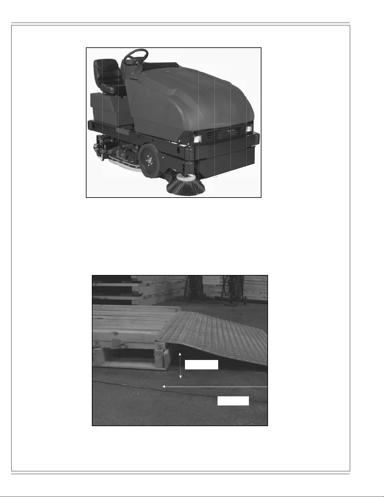
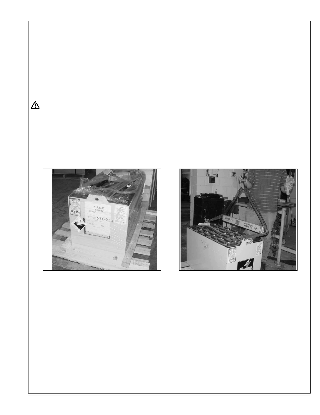
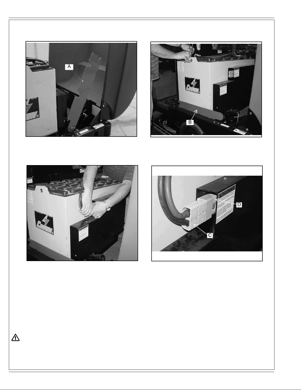
Uncrating the Machine................................................................................................A-3
Cautions and Warnings ..............................................................................................A-4
Consignes de prudence et de sécurité.......................................................................A-5
Machine Preparation ...................................................................................... A-6 – A-8
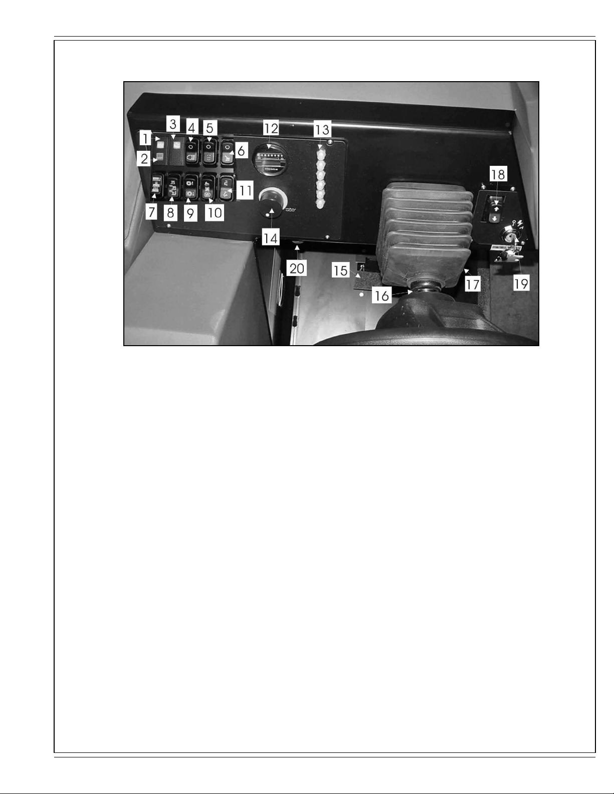
Controls......................................................................................................... A-9 – A-21
Front Console........................................................................................................A-9
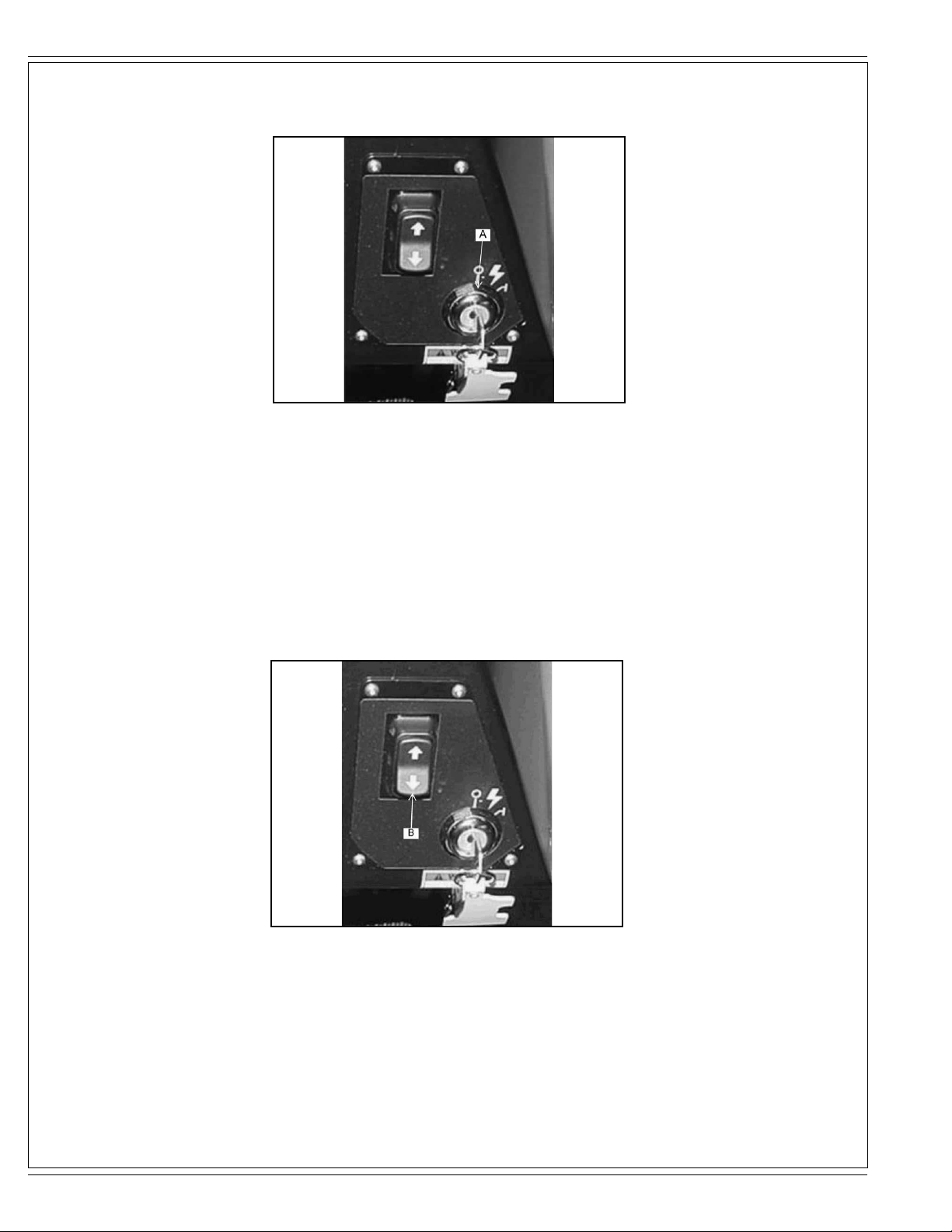
Key Switch...........................................................................................................A-10
Forward/Reverse Switch .....................................................................................A-10
Battery Condition & Hour Meter........................................................................... A-11
Headlight/Taillight Switch (Option)....................................................................... A-12
Hopper Open Warning Light................................................................................A-12
Filter Shaker Switch (Dust Control Models).........................................................A-13
Dust Control Switch.............................................................................................A-13
Scrub Brush Switch .............................................................................................A-14
Squeegee Switch.................................................................................................A-14
Low Solution & High Recovery Lights ................................................................. A-15
Hopper Lift Switch ............................................................................................... A-16
Main & Side Broom Switch..................................................................................A-16
Spray & Vac Wand Switch (Option).....................................................................A-17
Esp Switch (Option).............................................................................................A-17
Main Broom & Side Broom Adjustment Knobs.................................................... A-18
Solution Flow Knob..............................................................................................A-19
Horn Button .........................................................................................................A-19
Foot Pedal & Parking Brake ................................................................................A-20
Seat Position Adjustment.....................................................................................A-21
Seat Safety Features...........................................................................................A-21
Operating Instructions............................................................................... A-22 – A-30
Pre-Start Checklist...............................................................................................A-22
Filling Solution Tank.............................................................................................A-22
Starting Machine..................................................................................................A-23
Transporting Machine..........................................................................................A-23
The Cleaning Operation ...................................................................................... A-23
Standard & Esp Scrubbing Systems ................................................................... A-24
Hints For The Cleaning Operation.......................................................................A-25
Post-Operation Checklist.....................................................................................A-26
Draining The Recovery Tank ....................................................................A-26 – A-27
Inspecting Main Broom & Scrub Brushes............................................................A-28
Inspecting The Squeegees.................................................................................. A-29
Using The Dust Control Knob..............................................................................A-30
Checking The Hydraulic Fluid Level....................................................................A-30
Maintenance................................................................................................ A-31 – A-45
Service Chart............................................................................................A-31 – A-32
Maintenance Cautions.........................................................................................A-33
Battery Charging..................................................................................................A-34
Battery Removal.......................................................................................A-35 – A-36
Replacing Scrub Brushes....................................................................................A-37
Replacing Rear Squeegee .................................................................................. A-38
Draining Recovery & Solution Tanks ................................................................... A-39
Main Broom Maintenance.........................................................................A-40 – A-42
Side Broom Maintenance ....................................................................................A-43
Dust Control Filter Maintenance..........................................................................A-44
Dust Flap Maintenance........................................................................................A-45
Hydraulic System Maintenance...........................................................................A-45
Troubleshooting ......................................................................................... A-46 – A-47
Technical Specifications........................................................................................A-48

ENGLISH / A-3
FORM NO. 56041720 - 7730 - A-3
INTRODUCTION
This manual will help you get the most from your American-Lincoln Sweeper / Scrubber. Read it thoroughly before operating the machine.
References to “right” and “left” in this manual mean right or left as seen from the driver’s seat.
PARTS AND SERVICE
Repairs, when required, should be performed by your Authorized American-Lincoln Service Center, who employs factory trained service
personnel, and maintains an inventory of American-Lincoln original replacement parts and accessories.
Call the AMERICAN-LINCOLN INDUSTRIAL DEALER named below for repairs or service. Please specify the Model and Serial Number when
discussing your machine.
(Dealer, affix service sticker here.)
NAMEPLATE
The Model Number and Serial Number of your machine are shown on the Nameplate, located on the wall of the operator’s compartment. This
information is needed when ordering repair parts for the machine. Use the space below to note the Model Number and Serial Number of your
machine for future reference.
MODEL ________________________________________________
SERIAL NUMBER _______________________________________
Note: Reference the separately supplied engine manufacture’s maintenance and operator manual for more detailed engine specification and
service data.
UN-CRATING
Upon delivery, carefully inspect the shipping crate and the machine for damage. If damage is evident, save all parts of the shipping crate so that
they can be inspected by the trucking company that delivered the machine. Contact the trucking company immediately to file a freight damage
claim.
1 After removing the crate, remove the wooden blocks next to the wheels and any hold down straps.
2 Check the hydraulic oil level.
3 Read the instructions in the Preparing the Machine For Use section of this manual, then install the battery.
4 Place a ramp next to the front end of the pallet.
5 Read the instructions in the Operating Controls and Operating the Machine sections of this manual. Slowly drive the machine forward down
the ramp to the floor. Keep your foot lightly on the brake pedal until the machine is off the pallet.
CAUTION!
Use extreme CAUTION when operating this machine. Be certain that you are thoroughly familiar with all operating instructions before using this
machine. If you have any questions, contact your supervisor or your local American-Lincoln Industrial Dealer.
If the machine malfunctions, do not try to correct the problem unless your supervisor directs you to do so. Have a qualified company mechanic or
an authorized American-Lincoln Dealer service person make any necessary corrections to the equipment.
Use extreme care when working on this machine. Loose clothing, long hair, and jewelry can get caught in moving parts. Turn the Key Switch OFF
and remove the key before servicing the machine. Use good common sense, practice good safety habits and pay attention to the yellow decals on
this machine.
Drive the machine slowly on inclines. The drive pedal will control machine speed while descending inclines. DO NOT turn the machine on an
incline; drive straight up or down.

A-4 / ENGLISH
A-4 - FORM NO. 56041720 - 7730
CAUTIONS AND WARNINGS
SYMBOLS
American-Lincoln uses the symbols below to signal potentially dangerous conditions. Always read this information carefully and take the
necessary steps to protect personnel and property.
DANGER!
Is used to warn of immediate hazards that will cause severe personal injury or death.
WARNING!
Is used to call attention to a situation that could cause severe personal injury.
CAUTION!
Is used to call attention to a situation that could cause minor personal injury or damage to the machine or other property.
Read all instructions before using.
GENERAL SAFETY INSTRUCTIONS
Specific Cautions and Warnings are included to warn you of potential danger of machine damage or bodily harm.
WARNING!
*This machine shall be used only by properly trained and authorized persons.
*While on ramps or inclines, avoid sudden stops when loaded. Avoid abrupt sharp turns. Use low speed down hills.
*Keep sparks, flame and smoking materials away from battery. Explosive gases are vented during normal operation.
*Charging the battery produces highly explosive hydrogen gas. Charge battery only in well-ventilated areas away from open flame. Do not
smoke while charging the battery.
*Remove all jewelry when working near electrical components.
*Turn the key switch off (O) and remove the key, before changing the brushes, and before opening any access panels.
*Never work under a machine without safety blocks or stands to support the machine.
*Do not dispense flammable cleaning agents, operate the machine on or near these agents, or operate in areas where flammable liquids
exist.
*Do not clean this machine with a pressure washer.
*Only use the brushes provided with the appliance or those specified in the instruction manual. The use of other brushes may impair safety.
CAUTION!
*This machine is not approved for use on public paths or roads.
*This machine is not suitable for picking up hazardous dust.
*Use care when using scarifier discs and grinding stones. American-Lincoln will not be held responsible for any damage to floor surfaces
caused by scarifiers or grinding stones.
*When operating this machine, ensure that third parties, particularly children, are not endangered.
*Before performing any service function, carefully read all instructions pertaining to that function.
*Do not leave the machine unattended without first turning the key switch off (O), removing the key and applying the parking brake.
*Turn the key switch off (O) before changing the brushes, and before opening any access panels.
*Take precautions to prevent hair, jewelry, or loose clothing from becoming caught in moving parts.
*Use caution when moving this machine in below freezing temperature conditions. Any water in the solution or recovery tanks or in the hose
lines could freeze.
* The battery must be removed from the machine before the machine is scrapped. The disposal of the battery should be safely done in
accordance with your local environmental regulations.
*Do not use on surfaces having a gradient exceeding that marked on the machine.
*All doors and covers are to be positioned as indicated in the instruction manual before using the machine.
SAVE THESE INSTRUCTIONS

ENGLISH / A-5
FORM NO. 56041720 - 7730 - A-5
CONSIGNES DE PRUDENCE ET DE SÉCURITÉ
SYMBOLES
Les symboles reproduits ci-dessous sont utilisés pour attirer l’attention de l’opérateur sur des situations dangereuses. Il est donc conseillé de lire
attentivement ces indications et de prendre les mesures adéquates en vue de protéger le personnel et le matériel.
DANGER!
Ce symbole est utilisé pour mettre l’opérateur en garde contre les risques immédiats pouvant provoquer des dommages corporels graves, voire
entraîner la mort.
ATTENTION!
Ce symbole est utilisé pour attirer l’attention sur une situation susceptible d’entraîner des dommages corporels graves.
PRUDENCE!
Ce symbole est utilisé pour attirer l’attention de l’opérateur sur une situation qui pourrait entraîner des dommages corporels minimes, ou des
dommages à la machine ou à d’autres équipements.
Lire toutes les instructions avant d’utiliser l’appareil.
CONSIGNES GENERALES DE SECURITE
Les consignes spécifiques de prudence et de sécurité mentionnées ici ont pour but de vous informer de la survenance de tout risque de
dommages matériels ou corporels.
ATTENTION!
*Cette machine ne pourra être utilisée que par du personnel parfaitement entraîné et dûment autorisé.
* Evitez les arrêts subits lorsque la machine est chargée et se trouve sur des rampes ou des plans inclinés. Evitez les virages serrés. Adoptez une
vitesse réduite lorsque la machine est en descente. Ne nettoyez que lorsque la machine monte la pente.
*Eloignez les batteries de toutes flammes, étincelles ou substance fumigène. Les gaz explosifs sont ventilés pendant le fonctionnement normal.
*De plus, du gaz hydrogène explosif s’échappe des batteries lorsqu’elles sont en charge. Ne procédez au chargement des batteries que dans une
zone bien ventilée, loin de toute flamme. Ne fumez pas à proximité des batteries lorsqu’elles sont en charge.
*Otez tous vos bijoux lorsque vous travaillez à proximité de composants électriques.
*Positionnez la clé de contact sur off (O) et déconnectez les batteries avant de procéder à l’entretien des composants électriques.
*Ne travaillez jamais sous une machine sans y avoir placé, au préalable, des blocs de sécurité ou des étais destinés à soutenir la machine
*Ne déversez pas d’agents nettoyants inflammables, ne faites pas fonctionner la machine à proximité de ces agents ou d’autres liquides
inflammables.
*Ne nettoyez pas cette machine avec un nettoyeur à pression.
*Utilisez uniquement les brosses fournies avec l’appareil ou celles spécifiées dans le manuel d’instructions. L’utilisation d’autres brosses peut mettre
la sécurité en péril.
PRUDENCE!
* Cette machine n’est pas conçue pour une utilisation sur les chemins ou voies publics.
* Cette machine n’est pas conçue pour le ramassage des poussières dangereuses.
* N’utilisez pas de disques de scarificateur ni de meules. American-Lincoln ne pourra en aucun cas être tenue pour responsable des dommages
occasionnés à vos sols par ce type d’équipement (vous risquez également d’endommager le système d’entraînement des brosses).
* Lors de l’utilisation de cette machine, assurez-vous que des tiers, et notamment des enfants, ne courent pas le moindre risque.
* Avant de procéder à toute opération d’entretien, veuillez lire attentivement toutes les instructions qui s’y rapportent.
* Ne laissez pas la machine sans surveillance sans avoir, au préalable, coupé le contact, enlevé la clé de contact (O) et tiré le frein à main.
* Positionnez la clé de contact sur off (O) avant de remplacer les brosses ou d’ouvrir tout panneau d’accès.
* Prenez toutes les mesures nécessaires pour éviter que les cheveux, les bijoux ou les vêtements amples ne soient entraînés dans les parties
mobiles de la machine.
* Faites attention lorsque vous déplacez cette machine dans un endroit où la température peut descendre sous 0°. Car l’eau contenue dans les
réservoirs de solution ou de récupération ou dans les conduites risquerait de geler et par là même d’endommager les valves et raccords de la
machine. Rincez avec un liquide de lave-glace.
* Prenez soin d’enlever les batteries de la machine avant de mettre cette dernière au rebut. Pour ce qui est de l’élimination des batteries, conformez-
vous aux réglementations locales en matière d’environnement.
*N’utilisez pas sur des surfaces dont la pente dépasse celle mentionnée sur la machine.
*Toutes les portes et couvercles doivent être dans la position mentionnée dans le manuel d’instruction avant de mettre la machine en service.
CONSERVEZ SOIGNEUSEMENT CES INSTRUCTIONS

A-6 / ENGLISH
A-6 - FORM NO. 56041720 - 7730
MACHINE PREPARATION
FIGURE 1
Your 7730 battery machine has been shipped complete, but do not attempt to operate without reading the following instructions:
UNPACKING AND ASSEMBLING MACHINE
The 7730 is shipped on a pallet and held in place with wooden block to stop the machine from moving.
1) Remove wooden blocks holding machine in place.
2) Position a 11° and 48” (121cm) ramp on base of pallet.
11 DEGREE
48 INCHES
FIGURE 2

ENGLISH / A-7
FORM NO. 56041720 - 7730 - A-7
MACHINE PREPARATION
3) Push machine down the ramp onto a flat surface.
4) Install battery.
- Turn the key to the “O” position
- Lift the hood up and pull the battery lever up to the right.
- Use a battery lifting device with a 2000 LB. (907KG) capacity to place the battery into the battery tray.
- Push battery lever down to the left to lock the battery into place.
- Plug the battery power connector into the machine power connector.
- Lower the hood into place.
5) Charge battery as shown in the manual. Read battery manufacturer literature for battery care and maintenance.
WARNING!
Do not charge batteries on a concrete grounded surface. Hydrogen gas is formed during the charging operation and is explosive. Only
charge batteries in a well ventilated area with the lid open. Avoid any smoking, open flame, or electrical sparks.
FIGURE 3 FIGURE 4
UNPACKING BATTERY
The battery is shipped separately on a pallet wrapped in plastic as shown in figure 3. Remove the plastic and use a 2000 LB. (907KG) capacity
lifting device to lower the battery into the battery compartment as shown in figure 4.

A-8 / ENGLISH
A-8 - FORM NO. 56041720 - 7730
MACHINE PREPARATION
FIGURE 7 FIGURE 8
BATTERY INSTALLATION
1. Lift the machine front cover.
2. Fig 5. Rotate the battery lever (A) to the right.
3. Lower the battery into place using a 2000 LB. (907 KG) capacity lifting device.
4. Fig 6. Rotate the battery lever (B) to the left to lock the battery into place.
5. Connect battery wires according to manufacturer’s direction.
6. Fig 7 and 8. Connect the battery power connector (C) to the machine power connector (D).
7. Lower the machine front cover into place.
WARNING!
Do not leave charged batteries on concrete surface, they will discharge.
FIGURE 5 FIGURE 6

ENGLISH / A-9
FORM NO. 56041720 - 7730 - A-9
CONTROLS
FIGURE 9
1. High recovery light.
2. Low solution light
3. Hopper open light.
4. Light switch.
5. ESP switch.
6. Spray Vac Wand switch.
7. Scrub brush switch.
8. Squeegee switch.
9. Main side broom switch.
10. Filter shaker/Dust control switch.
11. Hopper switch.
12. Battery condition meter/Hour meter.
13. Circuit breakers.
14. Solution flow knob.
15. Parking Brake.
16. Steering wheel adjustment lever.
17. Foot throttle.
18. Forward/Reverse switch.
19. Key switch.
20. Horn

A-10 / ENGLISH
A-10 - FORM NO. 56041720 - 7730
CONTROLS
FIGURE 10
KEY SWITCH
The keyed ignition switch (A) is located on the ioperator’s console as shown in figure 10.
The “OFF” position (O position) will shut off the machine. The IGN/ON position (I position) provides power to all machine systems and
accessories.
FIGURE 11
FORWARD / REVERSE SWITCH
The forward/reverse switch (B) is located on the operator’s console as shown in figure 11. Pressing the upper half of the forward/reverse switch
will result in the machine moving forward when the foot throttle is depressed. Pressing lower half of the forward/reverse lever switch will result in
the machine moving backward when the foot throttle is depressed.

ENGLISH / A-11
FORM NO. 56041720 - 7730 - A-11
CONTROLS
FIGURE 12
BATTERY CONDITION METER
The battery condition meter (A) is located on the instrument panel as shown in figure 12. The condition meter indicates the level of charge in
the batteries. The batteries are sufficiently charged when all of the LED’s are illuminated amber as shown on the ramp illustration. Charge the
batteries when one red LED is illuminated on the left at the bottom of the ramp diagram and the scrub brushes stop. Do not operate the machine.
FIGURE 13
NOTE
To reengage, the key must be returned to the “OFF” position.
HOUR METER
The hour meter (B) is located on the instrument panel as shown in figure 13. Tthe diplay will show the total hours the machine has been in
operation. The meter is activated when the key switch is placed in the ignition position. The meter can be used to determine when maintenance
should be done on the machine.

A-12 / ENGLISH
A-12 - FORM NO. 56041720 - 7730
CONTROLS
FIGURE 14
HEADLIGHT/TAILIGHT SWITCH (Optional)
The light switch (A) is located on the instrument panel as shown in figure 14. By pressing on the lower half of the switch the headlights and
taillights will be activated. Pressing the upper half of the switch will turn off the lights.
FIGURE 15
HOPPER OPEN WARNING LIGHT
The hopper open light switch (B) is located on the instrument panel as shown in figure 15. When the hopper is open, the light is illuminated the
broom and the dust control fan will stop.

ENGLISH / A-13
FORM NO. 56041720 - 7730 - A-13
CONTROLS
FIGURE 16
FILTER SHAKER SWITCH (Only models with dust control)
The filter shaker switch (A) is located on the instrument panel as shown in figure 16. By pressing and holding in the upper half of the switch, it will
activate the filter shaker motors for 20 to 30 seconds. Releasing the switch, returns to the off position.
The dust control fan will stop when the filter shaker has been activated. The filter shaker will only operate with the hopper in the “DOWN” position.
FIGURE 17
DUST CONTROL SWITCH
The dust control switch (B) is located on the instrument panel as shown in figure 17. To turn on the dust control system for normal sweeping,
press the lower half of the switch.
WARNING!
Turn the dust control switch to the center “OFF” position while wet sweeping. Water will damage the filter and cause premature filter
failure.

A-14 / ENGLISH
A-14 - FORM NO. 56041720 - 7730
CONTROLS
FIGURE 18
SCRUB BRUSH SWITCH
The scrub brush switch (A) is located on the left of the instrument panel as shown in figure 18. Pressing the top half of the switch raises the scrub
deck and turns off the brushes. The middle switch position lowers the brushes to the normal down position for scrubbing. Pressing the lower half
of the switch lowers the scrub deck to the heavy down position, supplying additional downward pressure for extremely dirty surfaces.
NOTE
Lowering the scrub deck does not turn on the brushes. The brushes turn on automatically when the machine moves forward or reverse.
FIGURE 19
SQUEEGEE SWITCH
The squeegee switch (B) is located on the the instrument panel as shown in figure 19. Pressing the lower half of the switch lowers the squeegee
and activates the squeegee vacuum. Pressing the upper half of the switch will turn off the squeegee vacuum and raise the squeegee. In the
middle position the switch will raise the squeegee. In this position the vacuum remains on to allow vacuuming the water that is left in the squeegee
recovery hose. This prevents water from dripping on the floor with the squeegee raised. If the squeegee is lowered and the direction of the
machine is reversed (activated by the Drive pedal) the squeegee will automatically raise. Moving forward the squeegee will automatically return to
the lowered position.

ENGLISH / A-15
FORM NO. 56041720 - 7730 - A-15
CONTROLS
FIGURE 20
LOW SOLUTION LIGHT
The low solution warning light (A) is located on the instrument panel as shown in figure 20. The low solution warning light illuminates when the
solution tank is empty, marking the end of the scrubbing cycle.
FIGURE 21
HIGH RECOVERY LIGHT
The high recovery warning light (B) is located on the instrument panel as shown in figure 21. The light will illuminate approximately 5 minutes
before the recovery tank is full, giving ample time to complete the scrubbing cycle, before the mechanical float shuts off the vacuum to the
recovery tank.

A-16 / ENGLISH
A-16 - FORM NO. 56041720 - 7730
CONTROLS
FIGURE 22
HOPPER LIFT SWITCH
The hopper lift switch (A) is located on the instrument panel as shown in figure 22. The switch controls the operation of the hopper lift system. To
raise the hopper for dumping, press and hold the lower half of the switch until the hopper reaches the desired height, then release. To close the
hopper press in and hold the upper half of the switch until the hopper closes completely then release.
WARNING!
To prevent the hopper from closing while doing maintenance lock the hopper in the open position into place with the safety arm.
FIGURE 23
SIDE BROOM and MAIN BROOM SWITCH
The side broom and main broom switch (B) is located on the instrument panel as shown in figure 23. By pressing in the upper half of the switch,
the side and main broom are raised and turned off. To lower and turn on both brooms, press the lower half of the switch.

ENGLISH / A-17
FORM NO. 56041720 - 7730 - A-17
CONTROLS
FIGURE 24
SPRAY AND VAC WAND SWITCH (Optional)
The spray and vac wand switch (A) is located on the instrument panel as shown in figure 24. Pressing the bottom half of switch turns on the
vacuum motor and the solution pump. Pressing the top half of the switch turns the vacuum motor and solution pump off.
FIGURE 25
ESP SWITCH (Optional)
The ESP switch (B) is located on the instrument panel as shown in figure 25. The ESP switch transfers water from the recovery tank through a
filter and into the solution tank. When the switch is in the down position the pump will operate when the high recovery light is illuminated. Clean
the recovery tank when the tank is emptied.
NOTE
Do not place clean water in the recovery tank when using ESP option, the solution tank could become overfilled during operation.

A-18 / ENGLISH
A-18 - FORM NO. 56041720 - 7730
CONTROLS
FIGURE 26
SIDE BROOM ADJUSTMENT
The side broom adjustment knob (A) for changing the sweep height to compensate for broom wear, is located in front of the machine to the right of
the dust control filter as shown in figure 26. Turning the knob to the left (counterclockwise) will lower the side broom.
FIGURE 27
MAIN BROOM ADJUSTMENT
The main broom adjustment knob (B) for changing the sweep height to compensate for broom wear, is located in front of the machine to the right
of the dust control filter as shown in figure 27. Turning the knob to the left (counterclockwise) will lower the main broom.

ENGLISH / A-19
FORM NO. 56041720 - 7730 - A-19
CONTROLS
FIGURE 28
SOLUTION FLOW KNOB
The solution flow knob (A) is located on the instrument panel as shown in figure 28. Turning the knob clockwise will increase the flow of solution
and water. The farther the solution control knob is turned the heavier the flow of water and solution will be. Turning the knob counterclockwise will
decrease the flow of the water and solution. To turn the water and solution off turn the knob all the way counterclockwise.
NOTE
For best results, discontinue application of solution 10 feet before stopping or making a 90° or 180° turn.
FIGURE 29
HORN BUTTON
The horn button (B) is located on the instrument panel as shown in figure 29. The horn button is always active. Pressing the horn button will
sound the horn.

A-20 / ENGLISH
A-20 - FORM NO. 56041720 - 7730
CONTROLS
FIGURE 30
FOOT THROTTLE
The foot throttle (A) is located to the right of the brake pedal on the floor of the operator’s compartment as shown in figure 30. This pedal controls
the machine travel speed. Press the forward/reverse switch to chose the travel direction, and then press down on the foot throttle to move set the
machine in motion. Increase the foot pressure to increase the travel speed.
FIGURE 31
PARKING BRAKE
The parking brake is located on the floor of the machine left of the foot throttle as shown in figure 31. To set the parking brake, press down on the
foot pedal (B) and the press down the lock (C). To unlock the parking brake, push down on the upper portion of the foor pedal and release.
This manual suits for next models
1
Table of contents
Languages:
Other American-Lincoln Scrubber manuals

American-Lincoln
American-Lincoln 7760 User manual

American-Lincoln
American-Lincoln 505-945 User manual

American-Lincoln
American-Lincoln SR5730 User manual

American-Lincoln
American-Lincoln SC7740 Installation and operation manual

American-Lincoln
American-Lincoln Encore R Installation and operation manual

American-Lincoln
American-Lincoln SR9772 510-016 User manual

American-Lincoln
American-Lincoln 7760 User manual

American-Lincoln
American-Lincoln SC7750 IC User manual

American-Lincoln
American-Lincoln ALTO SMART 2000 User manual

American-Lincoln
American-Lincoln Encore S28 User manual