American-Lincoln SR9772 510-016 User manual

Electronic Service
Manuals
This electronic document is provided as a service to our customers.
Wedonotcreatethecontentsoftheinformationcontainedinthisdocu-
ment. Shouldyouhavedetailedquestionspertainingtotheinformation
contained in this document, you may contact Michco, or the manufac-
turer which provided the original information in this electronic deliver-
able. Michco’sonlypartin this electronic deliverable was the electronic
assemblyprocess. Byprovidingthismanualonlinewearenotguaran-
teeing parts availability.
You may contact Michco through the following methods:
Phone (517) 484-9312 or (800) 331-3339
2011 N. High St. -- Lansing, Michigan -- 48906
Fax: (517) 484-9836
Email: [email protected]
Web site: www.Michco.Com
Parts Web site: www.FloorMachineParts.Com
Order Parts on Line at:
www.FloorMachineParts.Com
Directly to Parts & Service:
By Fax: (517) 702-2041
By Voice: Use numbers above.
Serving the Cleaning Industry Since 1922
Notice: All copyrighted material remains property of original owners, all trademarks are property of respective owners.
ManualsaresubjecttoManufacturer’sreproductionlimitations. Originalsorreproductionswereprovidedbymanufacturers
through a request. We make no warranty as to the correctness of information provided in this document and you assume
allrisk. By placing thesemanualsonlinewe are notdeclaringourcorporation to be anmanufacturerauthorizeddealer or
provider, please check ourwebsiteforauthorizedmanufacturerswerepresent.

Instructions for Use / Parts List
READ THIS BOOK
This book has important information for the use and safe operation of this machine. Failure to read this book prior to operating or attempt-
ing any service or maintenance procedure to your machine could result in injury to you or to other personnel; damage to the machine or to
other property could occur as well. You must have training in the operation of this machine before using it.
All directions given in this book are as seen from the operator’s position at the rear of the machine.
Form Number 28600313 Revised 6/07 English
SR9772
SCRUBBER
For American-Lincoln MODELS 510-015, 510-016, 510-017, 510-018

1-2 American Lincoln
SR9772

American-Lincoln 1-3
SR9772
TABLE OF CONTENTS
CHAPTER 1 - CONTROLS & OPERATION
Machine Specifications......................................................................................................................................................1-4 – 1-5
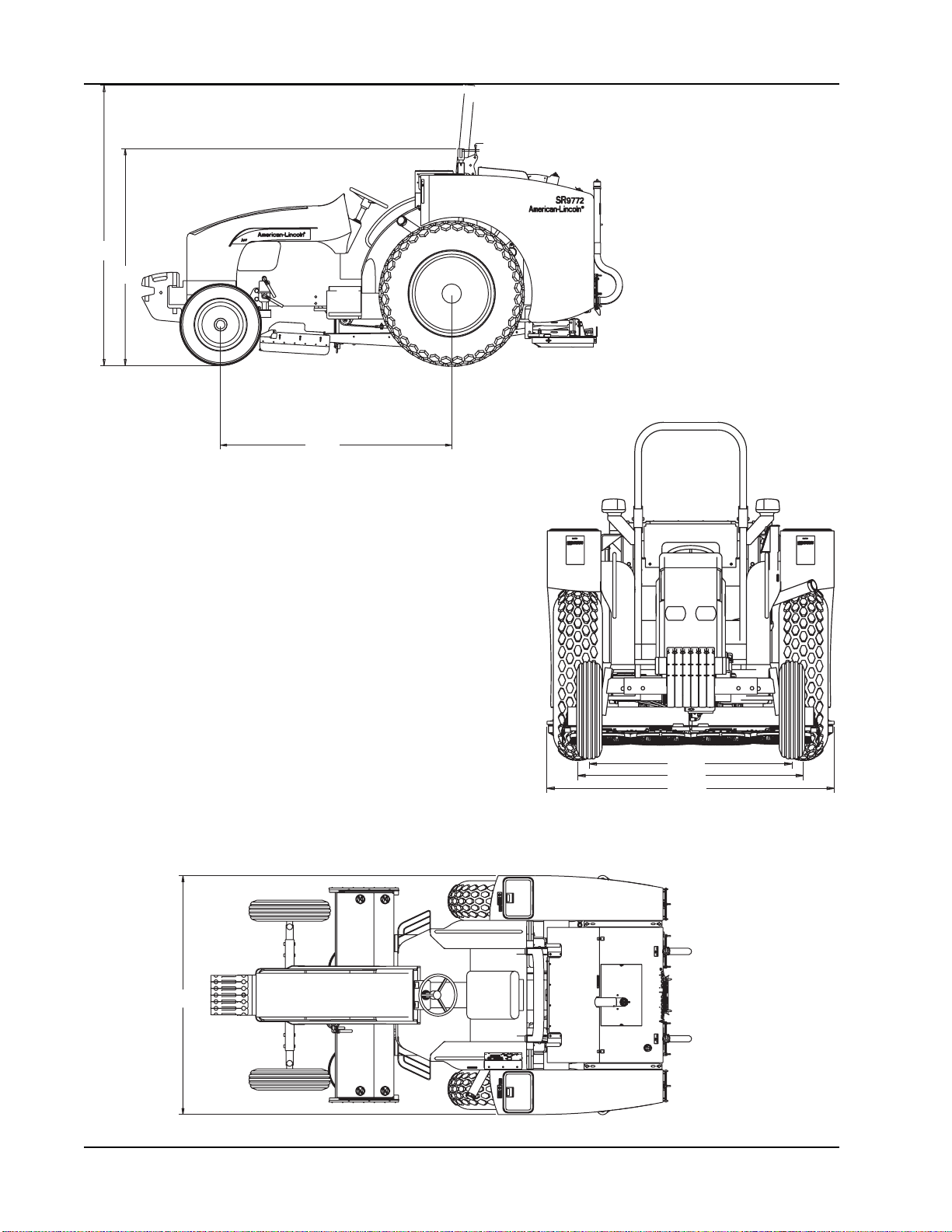
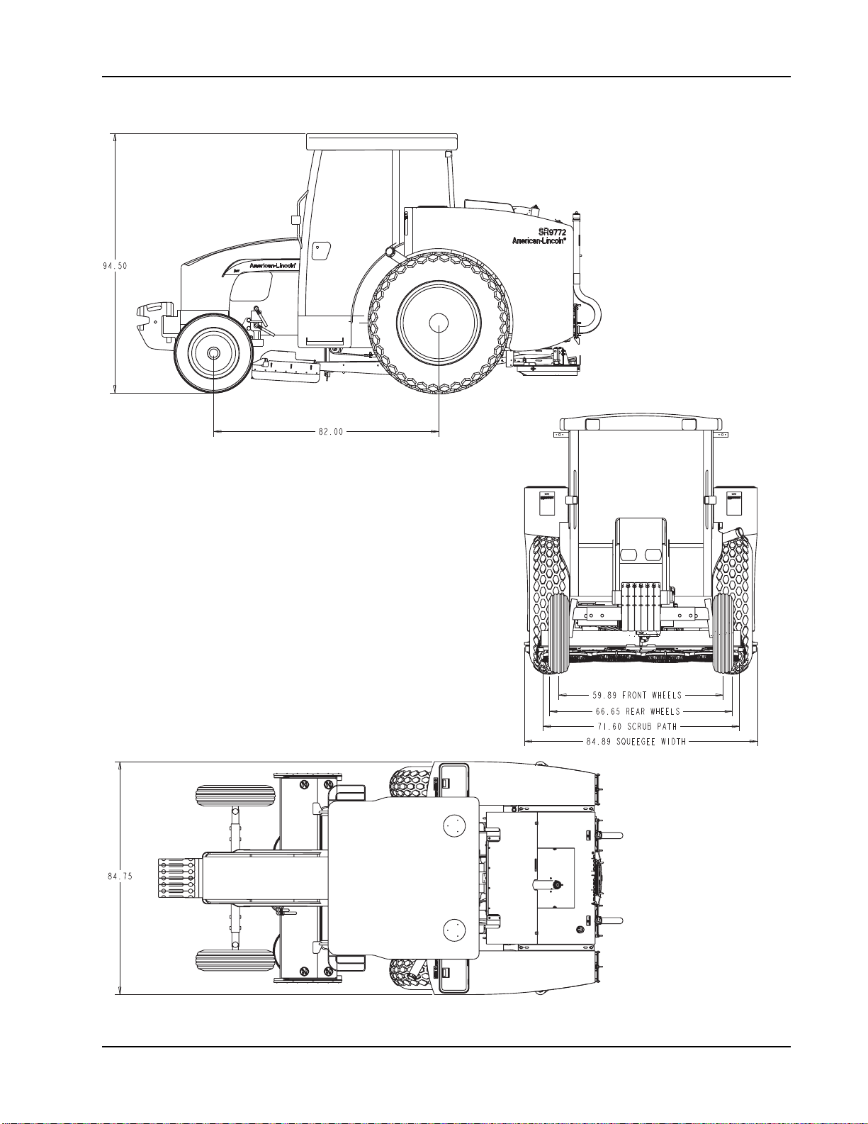
Machine Dimensions .........................................................................................................................................................1-6 – 1-7
Safety Precautions ............................................................................................................................................................1-8 – 1-9
Machine Information/Preparation .................................................................................................................................. 1-10 – 1-11
Scrubber Operation .......................................................................................................................................................1-12 – 1-13
The Scrubbing Systems ................................................................................................................................................1-14 – 1-15
Operating the Scrubber Controls...................................................................................................................................1-16 – 1-17
Operating Instructions ...................................................................................................................................................1-18 – 1-26
Service Chart............................................................................................................................................................................ 1-27
Service Instructions .......................................................................................................................................................1-28 – 1-33
Troubleshooting - Scrubbing System........................................................................................................................................ 1-34
Troubleshooting - Hydraulic System......................................................................................................................................... 1-35
Troubleshooting - Camel Recycling Pump ............................................................................................................................... 1-36
Troubleshooting - Camel Detergent Pump ............................................................................................................................... 1-37
Ordering Parts .......................................................................................................................................................................... 1-38
CHAPTER 2 - COMPONENT PARTS LISTS & DIAGRAMS
Mounting Structure ..................................................................................................................................................................... 2-2
Scrub Deck/Solution Control ...................................................................................................................................................... 2-4
Scrub Deck Lift (NO Cab)........................................................................................................................................................... 2-6
Scrub Deck Lift (CAB) ................................................................................................................................................................ 2-8
Squeegees/Squeegee Lift ....................................................................................................................................................... 2-10
Solution Tank............................................................................................................................................................................ 2-12
Solution Vacuum System..........................................................................................................................................................2-14
Solution Vac/Washer Hose (CAB) ............................................................................................................................................ 2-16
Recovery Tank.......................................................................................................................................................................... 2-18
Recovery Tank Lid.................................................................................................................................................................... 2-20
Camel Recovery Tank .............................................................................................................................................................. 2-22
Camel Pump Group.................................................................................................................................................................. 2-24
Camel Detergent Tank (NON-CAB).......................................................................................................................................... 2-26
Camel Detergent Tank (CAB)...................................................................................................................................................2-28
Hydraulic Manifold Valve .......................................................................................................................................................... 2-30
Hyd. Cylinders & Main Pump Hoses & Fittings .......................................................................................................................2-31
Hydraulic Motors, Hoses & Fittings .......................................................................................................................................... 2-32
Brush Drive Motors & Fittings................................................................................................................................................... 2-33
Control Panel Assembly ........................................................................................................................................................... 2-34
Decals....................................................................................................................................................................................... 2-36
Scrub Deck Hydraulics & Fittings ............................................................................................................................................. 2-38
Scrub Deck Flap Assemblies.................................................................................................................................................... 2-40
Hydraulic Schematic................................................................................................................................................................. 2-41
Electrical Schematic ................................................................................................................................................................. 2-42
CHAPTER 3 - OPTIONS
Brush Options............................................................................................................................................................................. 3-2
Foam-Filled Tires Option ............................................................................................................................................................ 3-3
Catalytic Muffler Option .............................................................................................................................................................. 3-4
Rotating Light Option (Roll Bar).................................................................................................................................................. 3-5
Warning Light Option (CAB) ....................................................................................................................................................... 3-6
Vacuum Wand Option.................................................................................................................................................................3-7
Transmission Lock-Out Option ................................................................................................................................................... 3-8
Additonal Options ....................................................................................................................................................................... 3-9
revised 6/07

1-4 American Lincoln
SR9772
MACHINE SPECIFICATIONS
DIMENSIONS
Length 137.4 inches (3489 mm)
Width 52.5 to 75.6 inches (1333 to 1920 mm)
Height 94.92 inches ( 2411 mm)
WEIGHT
Counterweights 925.9 to 1102lbs ( 420/500 kg)
Weight Cab Model Loaded 11168 lbs. (5076kg)
Weight Cab Model Unloaded 8168 lbs. (3713 kg)
Weight Platform Model Loaded 10384 lbs. (4720 kg)
Weight Platform Model Unloaded 7384 lbs. (3356 kg)
ENGINE
Injection Pump 4-stroke diesel direct injection, Naturally aspirated,3 cylinders:
Bore and Stroke 3.94 x 4.52 inches (104 x 115 mm)
Total Displacement 178.79 in³ (2930 cm³)
Compression Ratio 17:1
Torque increase 29%
Corresponding rpm 2000
Max Torque rpm 1400
Oil Cooler Engine oil-cooled by a heat exchanger using engine coolant.
FUEL SYSTEM
Fuel Pumps Double diaphragm fuel pump on injection pump supply line. Rotary injection pump with centrifugal
speed
governor, operating at all speeds and incorporating automatic advance. Type Bosch-VE3.
Fuel Filtration Mesh filter in the fuel pump; replacement cartridge filter on the injection pump feed line with water
separator.
Lubrication Pressurized by gear pump. Oil filtration: pressurized through pump intake mesh and replacement
cartridge filter on engine intake.
ENGINE LUBE PRESSURE
Engine Speed 2000rpm, bar 2.9-3.9, psi 42.24-55.47
Cooling Water, pressurized circulation by centrifugal pump. Radiator with 3 lines of vertical copper pipes.
Cooling fan fitted on same shaft as water pump. Water circulation from engine to radiator
thermostatically controlled.
AIR CINDITIONING
Cab Version Air conditioning is standard. Refer to New Holland for operation and filter information.
TRANSMISSION
Clutch Dry 11” double plate, with separate controls:
pedal operation for gearbox, traction clutch.
Gears 8 x 8 Synchro Command (platform models).
16 x 16 Synchro (cab models).
Steering Hydrostatic control, independent circuit. Paper oil filter with replaceable cartridge. Tilt steering.

American-Lincoln 1-5
SR9772
MACHINE SPECIFICATIONS
ELECTRICAL SYSTEM
Voltage 12V
Alternator 45Amp
Battery 12V capacity 88 Ah, sealed, maintenance-free.
LIGHTS Two asymmetrical front headlamps using 40/45 W bulbs.
Two asymmetrical front headlamps using low halogen bulbs.
Two front light clusters including: side lights, directional indicator.
Two rear light clusters including: side lights, directional indicator, brake light, number plate light. Red
rear reflectors.
INSTRUMENTS & ACCESSORIES
Multiple-function instrument panel, 7-pin 8 A DIN power socket, 25 A power socket, Thermo-start, and flashing hazard warning light.
CLEANING PATH 72 inches
TRANSPORT SPEED 2-8 mph
SCRUB SPEED 2-4 mph (refer to New Holland manual for proper gear selection)
TURNING RADIUS 127.6 inches
AISLE WIDTH FOR U-TURNS 11.5 feet
SOLUTION TANKS Two (2) 100 gallon capacity each, stainless steel
construction, crossover lines (hoses) allows filling from either side, clean-out doors and oversize fill
openings are standard.
RECOVERY TANK One (1) 210 gallon capacity, stainless steel construction, equipped with automatic vacuum shut-off float.
VACUUM SYSTEM Power provided by a regenerative air turbine, V-belt driven.
SCRUB BRUSHES Four (4) 18-inch diameter, disc type.
Brushes are mounted to a 3/8” steel frame and are readily accessible. Hydraulic cylinder raises and
lowers
brush assembly off ground level for travel and storage. Scrub brush discs are gimbal-mounted to follow
irregular floor contours.
One-piece or sectional brushes are available.
TIRES Front: Implement Tread (2) 6.50 - 16
Rear: Tutf Tires (2) 13.6 - 28
SQUEEGEE ASSEMBLY Rear: Para-Bolic 80-inch (203.2 cm) break-away with no-tool squeegee replacement.
Side: 26 in (66 cm) Easy Change
OPTIONAL BRUSHES Bassine Amergrit
Supergrit Soft Nylon
Straight wire Amerfil (.025)
Nylon Amerfil (.040)
Amerfil & wire (one-piece only)

1-6 American Lincoln
SR9772
MACHINE DIMENSIONS
PLATFORM MODEL (TOP VIEW)
PLATFORM MODEL (REAR VIEW)
PLATFORM MODEL (SIDE VIEW)
99.33
82.00
59.89
66.65
84.89
84.75
.67
76.91
c0976/1202

American-Lincoln 1-7
SR9772
MACHINE DIMENSIONS
CAB MODEL (SIDE VIEW)
CAB MODEL (REAR VIEW)
CAB MODEL (TOP VIEW)

1-8 American Lincoln
SR9772
SAFETY PRECAUTIONS
FOR SAFETY, OBSERVE THE FOLLOWING WARNINGS. FAILURE TO COMPLY MAY CREATE A SERIOUS RISK OF INJURY TO
YOU AND OTHERS. THIS MACHINE SHOULD NOT BE USED IN HAZARDOUS LOCATIONS, INCLUDING AREAS OF VOLATILE
DUST OR VAPOR CONCENTRATIONS.
READ THE MANUAL CAREFULLY. UNDERSTAND WHEN THESE CONDITIONS CAN EXIST; THEN TAKE NECESSARY STEPS
TO TRAIN PERSONNEL WHO WILL OPERATE THIS MACHINE. FOR THE SAFE OPERATION OF THIS MACHINE, READ AND
UNDERSTAND ALL WARNINGS, CAUTIONS AND NOTES.
THE FOLLOWING STATEMENTS ARE USED THROUGHOUT THIS MANUAL AS INDICATED IN THEIR DESCRIPTIONS:
DANGER - To warn of immediate hazards which will result in severe personal injury or death.
WARNING - To warn of hazards or unsafe practices which could result in severe personal injury or death.
CAUTION - To warn of hazards or unsafe practices which could result in minor personal injury.
ATTENTION - To warn of unsafe practices which could result in extensive equipment damage.
NOTE - To give important information or to warn of unsafe practices which could result in equipment damage.
WARNING
Machines can ignite flammable materials and vapors. Do not use with or near flammables
such as gasoline, grain dust, solvents, and thinners.
WARNING
Improper use of heavy machinery can cause personal injury.
WARNING
Operate only when lids, doors, and access panels are securely closed.
WARNING
Use care when reversing machine in confined area.
WARNING
When servicing the machine, disconnect the batteries first to prevent possible injury.
WARNING
When working on the machine, empty hopper, remove batteries, clear area of people and obstructions,
use additional people and proper procedures when lifting the machine.
WARNING
Always empty the hopper and disconnect the battery before doing maintenance.
WARNING
You must have training in the operation of this machine before using it. READ THE INSTRUCTION BOOK.
WARNING
Do not operate this machine unless it is completely assembled.
WARNING
Do not use this machine as a step or furniture.
WARNING
Stop and leave this machine on a level surface. When you stop the machine,
put the power switch in the “OFF” position and engage the Parking Brake.

American-Lincoln 1-9
SR9772
SAFETY PRECAUTIONS
WARNING
To prevent injury and damage to the machine, do not lift the machine
or move it to an edge of a stair or loading dock.
WARNING
Lead acid batteries generate gases which can cause an explosion. Keep sparks and flames away from batteries. NO SMOKING.
Charge batteries only in areas with good ventilation.
WARNING
Always wear eye protection and protective clothing when working near batteries. Remove all jewelry. Do not put tools or other metal
objects across the battery terminals or across the tops of batteries.
WARNING
Maintenance and repairs must be done by authorized personnel only. Tighten all fasteners. Maintain adjustments according to
the specifications given in the service manual for the machine. Keep the electrical parts of the machine dry. For storage, keep the
machine in a building.
WARNING
Make sure all labels, decals, warnings, cautions and instructions are fastened to the machine.
Purchase new labels and decals from American-Lincoln.
WARNING
The operator must exhibit extreme caution when negotiating, turning, and traveling across grades or ramps.
Start, stop, change direction, travel and brake smoothly. Slow down when turning.
WARNING
Avoid uneven surfaces and loose materials. Watch for obstructions, especially overhead.
WARNING
Operate only from the designated operator’s position. Stay inside the body of the machine. Keep hands and feet on the designated
controls. Always operate in well lighted areas.
WARNING
Do not carry passengers on the machine. Set the Parking Brake when leaving the machine. Chock (block) the wheels if the machine
is parked on a grade (ramp), or is being prepared for Maintenance.
WARNING
Never leave the operator’s compartment with engine running.
WARNING
Report damage or faulty operation immediately. Do not operate the machine until repairs have been completed. Maintenance and
repairs must be done by authorized personnel only.
WARNING
To maintain the stability of this machine in normal operation, the overhead guard, counterweights, roller bumper guards, or any similar
equipment installed by the manufacturer as original equipment should never be removed.
If it becomes necessary to remove such equipment for repair or maintenance, this equipment must be reinstalled before the machine
is placed back into operation.
WARNING
Electrical hazard. Shocks can cause serious personal injury. Unplug the battery before cleaning or servicing.
To avoid possible injury or property damage, read the Operator’s Manual before servicing the machine.
Maintenance and repair must be done by authorized personnel.
WARNING
Disconnecting the battery connector with the key switch in the “I” position will cause sparks that could ignite explosive hydrogen
gas generated by the batteries. To prevent serious injury or possible property damage, turn Key Switch to “O” position before
disconnecting the battery cable from the machine for charging or service.

1-10 American Lincoln
SR9772
MACHINE INFORMATION/PREPARATION
TOWING THE SCRUBBER
NOTE: The scrubber must only be towed for short distances. For example, from inside a building to the outside. It must never be
towed for long distances on the road in heavy traffic.
NOTE: To transport the scrubber, load it, complete with its four tires, onto a truck.
Should it be necessary to tow the scrubber, use a strong chain. Tow the scrubber from the rear using only the drawbar, the rear tow-
hitch or three-point linkage. Tow the scrubber from the front using the tow-hitch fitted to the front support or ballast. THE SCRUBBER
MUST BE TOWED WITH A DRIVER ON BOARD TO STEER AND STOP THE SCRUBBER WHEN NECESSARY.
To avoid damaging the transmission or other components which turn but are not lubricated during towing, observe the following:
1. Only tow for short distances
2. Do not exceed 5 mph (8 km/h)
3. If possible, run the engine to lubricate the power steering components
4. Position the gear and range levers in neutral
CAUTION
Never use ropes or cables to tow the scrubber.
These may slip or break, presenting the risk of serious injury.
CAUTION
Never exceed 5 mph (8 km/h) when towing.
Effort to control steering is much greater and response much slower.
LOADING THE SCRUBBER ON A TRANSPORTER
Load the scrubber with all four wheels on the truck platform or flatbed trailer.
Secure the scrubber to the transporter with suitable chains.
Secure the front of the scrubber using the towing hitch; secure the rear using the tow bar or tow bar supports.
WARNING
Do not hook or connect chains around the front axle transmission shaft,
power steering cylinders, front axle, or other parts of the scrubber that could be damaged
by the chains or excessive strain during transport.

American-Lincoln 1-11
SR9772
MACHINE INFORMATION/PREPARATION
MACHINE PREPARATION
YOUR AMERCAN-LINCOLN SR9772 HAS BEEN SHIPPED COMPLETE, BUT DO NOT ATTEMPT TO
OPERATE WITHOUT READING THE FOLLOWING INSTRUCTIONS:
1. Fill tank with diesel fuel only
WARNING
Never fill fuel tank while the engine is running.
2. Check engine crankcase oil level. Although properly lubricated at factory, check before starting engine. No special break-in oil
is used and recommended number of operating hours before the initial oil change is 50 hours. See lubrication and maintenance
section of the New Holland manual.
3. Check radiator coolant level. Permanent type antifreeze is added at the factory to provide protection to approximately -35ºF. To
retain this protection level, always add ½ part water to ½ part anti-freeze.
4. In addition to regular service operations listed, the following items should be checked every 10 hours or daily during the first 50
hours of operation.
-Engine Oil Level
-Rear Axle Oil Level (at turbine cover access)
-Rear Wheel Nuts for Tightness
NEW HOLLAND TN60 TRACTOR POWER UNIT
The American-Lincoln SR9772 utilizes a NEW HOLLAND TN60 as the power unit. The power unit provides hydraulic power for the
brush drive, squeegee, solution vacuum, brush position and squeegee position
functions.
This manual includes some pertinent NEW HOLLAND Operator’s Manual infomation for the SR9772. Consult the NEW HOLLAND
TN60 Operator’s Manual for all tractor maintenance, service and other detailed tractor-related information. Parts for the TN60 power
unit are available from your local NEW HOLLAND Dealer.

1-12 American Lincoln
SR9772
SCRUBBER OPERATION
CHECKS BEFORE USING THE SCRUBBER
Before using the scrubber, make sure you are familiar with the position and function of all controls. Ensure the maintenance and
lubrication operations described in the NEW HOLLAND manual have been carried out, followed by a visual inspection of the outside
of the scrubber. Give particular attention to the following:
1. Check the air filter and levels on the oil, coolant, hydraulic fluid and fuel.
2. Signs of leaks or damaged components connected to pressure tubes, sleeves and connectors.
3. Signs of cracking on the fanbelt.
4. Accumulation of foreign matter or leaks around the engine and hydraulic pump and related hoses.
5. Loose fasteners.
Always complete any necessary repairs before using the scrubber.
SAFETY COVERS
The scrubber is fitted with covers designed for the personal safety of the operator and others when in use. The BONNET covers the
moving parts of the engine and must be closed before starting. The fan has
COVERS on both the left and right sides.
CAUTION
Before starting the engine or using the scrubber, always make sure all safety covers, panels and access doors are securely closed.
Before starting the engine or moving the scrubber, follow these instructions:
1. Do not start or operate the scrubber in an enclosed area.
2. Before starting the engine, make sure all controls are in neutral and the parking brake is set.
3. Operate controls from driver’s position only.
4. Stop engine before performing any service or maintenance operations.
5. Use the steps provided for entering and exiting the scrubber.
6. When driving on roads, indicate all intentions to stop, turn or slow down; use appropriate warning devices to indicate a slow-
moving vehicle.
CAUTION
When SHIFTING from one range to another, forward to reverse, or reverse to forward, the operator MUST reduce the speed (throttle)
to LOW IDLE, shift range and/or gear, then increase the speed (throttle).
STARTING THE ENGINE
1. If the scrubber has not been used for some time, or is being started for the first time in low outside
temperature conditions, operate the fuel pump starting lever approximately 20 times.
2. Press down the clutch pedal, place the shuttle control lever in neutral to close the starting safety device switch.
3. Move the throttle lever to approximately the halfway position.
4. Turn the starter key and release as soon as the engine starts.
STARTING IN LOW OUTSIDE TEMPERATURES
When the outside temperature is low and the engine cold, cover the radiator before starting so the engine coolant can quickly reach
the correct temperature, then remove the cover. To avoid running down the battery, any single attempt to start the engine should last
no longer than 15 seconds. If, however, the engine fires but does not start, continue attempt for up to 30 seconds. Wait at least one
minute between each attempt to start the engine. To avoid excessive depletion of battery, make no more than six attempts at starting.
STARTER KEY SWITCH
The following three positions appear on this switch:
A -No power supply to any of the circuits (key can be removed); engine stops - injection shutoff activates automatically.
B -Standby for engine start-up; indicator and control instruments ON.
C -Engine start-up (when released, key automatically returns to position B).

American-Lincoln 1-13
SR9772
SCRUBBER OPERATION
STARTING WITH THE THERMOSTART
Carry out pre-start operations as previously described; turn starter switch key to position B (stand-by); turn on the thermostart by
pressing pushbutton and hold for 25 seconds; move starter switch key to position C while holding down the thermostart button until
engine starts. Once the engine has started, release both the key and thermostart button. If after two or three attempts the engine has
not started and black smoke is coming from the exhaust, start engine without using the thermostart.
CAUTION
When starting the engine after an extended period of non-use, avoid using the hydraulic system immediately since all moving parts
will require lubrication before they are subjected to full load. Especially when the outside temperature approaches 0º C (32º F), run
the engine at 1300-1500 rpm for approximately five minutes to heat the rear transmission oil to working temperature.
CAUTION
If any warning lights illuminate to signal a fault, check and repair the faulty part. If the warning light continues to signal a fault, have
the scrubber checked by your NEW HOLLAND dealer.
CAUTION
When the outside temperature is below 0º C, in order to prevent separation of the parrafin components in the diesel fuel which leads
to a reduction in fluidity and subsequent fuel supply problems, mix the diesel fuel with antifreeze (or similar product) in the proportions
described on the container. Put the antifreeze in the tank first, followed by the fuel. The antifreeze will ensure there is optimum
fuel supply to the engine without reducing performance (up to -20º C/-68º F). The diesel must be mixed with the antifreeze before
any sign of parrafin separation - adding it later will have no effect on the engine if the cold has already caused it to stop running or
prevented it from starting.
TO DRIVE MACHINE (FOR TRANSPORT)
Follow these steps to drive (transport) the machine to the area to be cleaned.
1. Be sure the scrub brushes and the squeegee are in the “up” position with all other controls in the “OFF” position.
2. Release the parking brake.
3. Depress the clutch and move the gear and range levers to desired positions, slowly release clutch while depressing accelerator.
4. To stop, reduce speed, depress clutch and apply brakes. When scrubber is stationary, reduce to low idle, move range and
gearshift levers into neutral, release the clutch and set the parking brake.
CAUTION
When SHIFTING from one range to another, forward to reverse, or reverse to forward, the operator MUST reduce the speed (throttle)
to LOW IDLE, shift range and/or gear, then increase the speed (throttle).

1-14 American Lincoln
SR9772
SOLUTION
TANK RECOVERY
TANK
FILTER
SCRUB
BRUSH SQUEEGEE
FLOOR CONTACT
THE SCRUBBING SYSTEMS
P4759
WITHOUT CAMEL SYSTEM
STRAINER
HOW IT WORKS (Without Camel System)
During the scrubbing process, a solution of detergent and water from the solution tanks is fed through the solution lines where it is
disbursed to the floor through the four scrubbing brushes that aggressively work to dislodge dirt and grime.
As the machine moves forward, the solution vacuum system lifts dirty water and debris from floor surface, through the squeegee tools
and a recovery tank air/water separation system. A float switch in the tank activates an indicator light on the control panel when the
water level in the tank becomes too high. Debris and sludge settle to the bottom of the recovery tank.

American-Lincoln 1-15
SR9772
SOLUTION
TANK RECOVERY
TANK
FILTER
FLOW
VALVE
SCRUB
BRUSH SQUEEGEE
FLOOR CONTACT
FILTER
SOLUTION
PUMP
SEPARATOR
DETERGENT
PUMP
DETERGENT
TANK
P4759camel
CAMEL SYSTEM
THE SCRUBBING SYSTEMS
HOW IT WORKS (with Camel System)
During the scrubbing process, filtered water from the solution tank is fed through the solution lines where it combines with the
detergent from the metering pumps. This mixture is then fed to the floor where four disc scrubbing brushes aggressively work to
dislodge dirt and grime.
After scrubbing, the used solution is vacuumed from the floor and discharged into the containment chamber of the recovery tank.
Once there, a system of baffles helps to clarify the solution on its way to the pumping chamber of the recovery tank. At intervals, a
system of sensors activates the recycling pump which sends filtered solution from the pumping chamber on its way to the centrifugal
separator which further aids clarifying of the solution for re-use. In the separator, solids are removed and purged into the containment
chamber. The solids-free solution is then fed up through the separator outlet and into the solution tank where it is ready to be mixed
with fresh, metered detergent, allowing the cleaning process to continue.

1-16 American Lincoln
SR9772
OPERATING THE SCRUBBER CONTROLS
D
1
23456
7
8
9
10
1. Solution Flow Knob - To control flow of water to scrub deck brushes once the scrub deck switch is engaged, rotate knob
clockwise from the OFF position shown. Solution flow can be controlled from 0 GPM (OFF position) to 6.0 GPM in the full ON
position (approximately 115º from OFF position). Solution will only flow when brushes are in scrub mode.
2. Scrub Deck Switch - Momentary contact switch, pressing the lower portion will lower the scrub deck, open the solution flow
valves, and initiate brush rotation. Pressing the upper portion (up position must be HELD for 1-2 seconds) will raise the scrub
deck, close the solution flow valves, and stop brush rotation.
3. Brush Rotation Switch - To control brush rotation once the scrub deck switch is engaged, utilize this two-way switch. Pressing
the upper portion will result in the brushes rotating clockwise; pressing the lower portion will cause the brushes to rotate
counterclockwise.
4. Squeegee/Vac Fan Switch - Pressing momentarily the contact switch switch will lower the squeegee and turn on the vacuum
fan; pressing the upper portion will raise the squeegee and shut off the vacuum fan. IF THE MACHINE IS PLACED IN
REVERSE, the squeegee automatically raises and the vacuum system shuts off. Normal operation will resume once the
machine is placed in neutral or returns to its forward motion.
5. Option Switch.
6. Camel recycling switch (if equipped).
7. Warning Light (if equipped) - top light indicates recirculation system activation, bottom light indicates low detergent.
8. Warning Light - RED indicates RECOVERY TANK FULL..
9. Warning Light - high solution light indicates the solution tank is full, low solution light indicates the solution tank is low.
10. Camel Detergent Control Knob (if equipped).

American-Lincoln 1-17
SR9772
OPERATING THE SCRUBBER CONTROLS
HYDRAULIC LEVER
HYDRAULIC LEVER
If the squeegee is in the down position and the tractor shift lever is moved into the reverse position, the squeegee will automatically
raise and the solution vacuum will turn off. Once the shift lever is returned to the forward or neutral position, the squeegee will
automatically lower and the solution vacuum will be turned on
Cab Model Platform Model
Prior to engaging any of the switches on the control panel, the tractor’s hydraulic lever must be engaged by pulling it back.
During transport, make sure the scrub deck and squeegee are in the raised position and the tractor hydraulic lever is in the
FORWARD/OFF position.

1-18 American Lincoln
SR9772
CONTROL PANEL
HYDRAULIC CONTROL LEVER
PULL BACK TO DE-ENERGIZE
PULL FORWARD TO ENERGIZE
PARKING BRAKE
OPERATING INSTRUCTIONS
PULL BACK TO ENERGIZE PUSH FORWARD TO
DE-ENERGIZE
HYDRAULIC CONTROL LEVER
NORMAL SCRUBBING MODE
Operating Instructions:
1. Access the scrubber.
2. Check all the scrubbing system controls, verifying they are in the off
position.
3. Confirm the hydraulic control lever is in the off position (all the way forward).
4. Follow the New Holland operations manual for start-up.
5. Pull the hydraulic control lever back to energize.
6. Activate the switches at the control panel to raise the scrub deck and
squeegee. The scrub deck and squeegee system switches are momentary-
contact switches. Press and hold the switch in upward position for 2
seconds and release. The switch will return automatically to a neutral
position. Confirm the scrub deck and squeegees are in the raised position.
7. Push the hydraulic control lever forward to off/de-energize.
8. Move the scrubber to filling station by first reducing the throttle to low idle
following start-up, depress clutch, select range and gear, slowly release
clutch and increase throttle.
CAUTION
When SHIFTING from one range to another, forward to reverse, or reverse to
forward, the operator MUST reduce the speed (throttle) to LOW IDLE, shift range
and/or gear, then increase the speed (throttle).
9. To stop and shut down the machine, depress clutch and reduce throttle to
low idle, move range and gear levers to neutral, apply brakes. When fully
stopped, apply the parking brake and turn off engine.

American-Lincoln 1-19
SR9772
OPERATING INSTRUCTIONS
FILL SOLUTION TANK
CLOSED SOLUTION TANK
SOLUTION FLOW KNOB
10. Open the solution tank access door on top of each tank.
11. Fill the solution tanks with water. (The solution tanks are linked together,
so you can fill through one access door. Add the recommended amount
of detergent to each solution tank allowing for even chemical dispersion).
(Each tank has a capacity of 100-gallons).
12. The high solution light on the scrubber control panel will illuminate when
the solution tanks are full.
13. While the solution tanks are filling, inspect machine. (Check and clean out
doors, ensuring the doors are sealed properly; inspect squeegee blades.
Perform maintence as required.)
14. Close the solution tank access doors once the tanks are filled.
15. Start the tractor following New Holland operating instructions, release
the parking brake, and drive the scrubber to work area by first reducing
the throttle to low idle following start-up, depress clutch, select range and
gear, slowly release clutch and increase throttle.
16. Stop the machine by depressing the clutch and reducing throttle to low
idle, move range and gear levers to neutral, apply brakes.
17. Depress clutch and select the appropriate gears to scrub at a speed of
2-3 mph (Low range is suggested).
18. Activate scrub deck and squeegee switches on the scrubber control panel
19. Pull the hydraulic control lever back to energize.
20. Begin scrubbing.
CAUTION
When SHIFTING from one range to another, forward to reverse, or reverse
to forward, the operator MUST reduce the speed (throttle) to LOW IDLE, shift
range and/or gear, then increase the speed (throttle).
21. Adjust the water flow by turning the solution flow knob located on control
panel to optimize scrubbing performance.
This manual suits for next models
3
Table of contents
Other American-Lincoln Scrubber manuals

American-Lincoln
American-Lincoln Encore R Installation and operation manual

American-Lincoln
American-Lincoln SR5730 User manual

American-Lincoln
American-Lincoln 56515851 User manual

American-Lincoln
American-Lincoln Alto SR7770HC User manual

American-Lincoln
American-Lincoln 7760 User manual

American-Lincoln
American-Lincoln Encore S28 User manual

American-Lincoln
American-Lincoln SC7750 IC User manual

American-Lincoln
American-Lincoln 505-945 User manual

American-Lincoln
American-Lincoln ALTO SMART 2000 User manual

American-Lincoln
American-Lincoln SC7740 Installation and operation manual