manuals.online logo
Brands
  1. Home
  2. •
  3. Brands
  4. •
  5. American Standard
  6. •
  7. Boiler
  8. •
  9. American Standard Aerozen G2 User manual

American Standard Aerozen G2 User manual

.
J
G-2
GAS BOILER
by
AMERICAN
-$tandattd
INSTALLATION
-OPERATION
AND
MAINTENANCE
MANUAL
SUPPLEMENT
NON-
PACKAG
.
ED
FOR
STEAM
BOILERS
WITH
FLUSH
OR
DELUXE
JACKETS
APPROVED
BY
AMERICAN GAS
ASSOCIATION
NOTICE
TO INSTALUI
AND
OPEIATOI
THIS
IOOKlET
MUST
II
AFFIXED
ON
Ol
ADJACENT
TO
THE
HEATING
~MENT
_AmRICAN-$taftdattef
..................................
BP-5-G2
Sup.
11EV.
11
~rl
CLICK ANYWHERE on
THIS PAGE to RETURN
to AMERICAN
STANDARD HEATER IO
MANUALS & AGE at
InspectApedia.com
t
13
G-2
STEAM
GAS
BOn.ER
2"
FLOW
Fig.
1
Boiler
with
Deluxe
Jacket
t
1
BOILER
No.
OF
No.
OF
A B c 0
NUMBER
SECTIONS BURNERS
G-230
3 2
13
Va
6~6
4
11
5
1!
G-240
4 3
16~
8~6
5 19"2
G-250
5 4
19%
91~6
5 19"2
G-260
6 5 22Ys
11~6
6
19
G-270
7 6
26
Va
13
!-;
6 6
19
G-280
8 7
29~
141ks
7
19~
G-290
9 8
32~
16
~6
7
19\
G-2100
10
9 35Ys
171~6
8
19~
G-211 0
II
10
39
Va
19
~6
8
19Ve
NOTE-:
EXTERNAL
DRAFT
HOOD IS ONLY
PROVIDED FOR
G-23-D
BOILER
p::;~:;;=~::;-
d
__
r~~:~
BOILER No. OF No. OF A B c 0 E
NUMBER
SECTIONS BURNERS
G-23F
3 2
II
51/2
4
13
7
G-24F
4 3
14
1
/4 7Va 5
13
3
~
7
G-25F
5 4
11
v2
8~4
5
133/4
7
G-26F
6 5
20~4
10~
8
6
16
1
/2 9
G-27F
']
6
24
12
6
16
y2
9
G-28F
8 7
27~
13~
8
7 203/4
12
G-29F
9 8
30V
2
15~
7
20
3
/4
12
G-210F
10
9
33~4
16'V
8 8 253
/4
16
G-211
F
II
10
37
18Y
2 8
25
3
/4
16
SIDE
FRONT
VIEW
Fig.
2
Boiler
with
Flush
Japket
•
...
.
3
4
5
G-2
STEAM
GAS
BOILER
c 2•
FLOW
c
2'
RETURN
SIDE VIEW FRONT VIEW
SECTION ASSEMBLY
SHOWING
TAPPINGS
FOR
STEAM BOILER
CONTROL APPLICATION
LOCATION
SIZE
OF
CONTROLS
ON
BOILER
TAPPING
A 3"
BLOW-OFF
B I "
"2
PRESSURE
GAGE
c 3 "
~
SAFETY VALVE
Fig.
3 -
Location
of
Tappings
for
Boiler
Controls
2"
SUPPLY
__
_
CONNECTION
FOR
HARTFORD
RETURN
EQUALIZER
PIPE
I
~,FOR
G-23
THRU
G-27
2"FOR
G-28
T
HRU
G-211
2 1
Fig.
4 -
Boiler
with
Flush
Fig.
5 -
Boiler
with
Deluxe
Type
Jacket
Type
Jacket
1.
Junction
Box
4.
Siphon
Fitting
2.
Safety
Valve
5.
Low
Water
Cutoff
3.
Steam
Limit
Control
6.
Water
Gauge
2
G-2
STEAM
GAS
BOILER
REFER
TO
WATER
BOILER
INSTALLATION
MANUAL
(Form BP-5-G2)
PACKED
IN
PLATEJWRK
AND
CONTROL
BOX
FOR
DETAILS
NOT
INCLUDED
IN
THIS
SUPPLEMENT.
INSTALLATION
OF
JACKET
-
Proceed
as
directed
in
the
Installation
Manual
for
water
boilers,
with
the
following
exceptions:
3
FLUSH
TYPE
JACKET
-
Select
L.H.
Side
Panel
(has
7-5/0
11
diameter
knockout)
and remove
this
knockout
for
all
steam
boilers
also
two
knockouts
for
water
gauge
connections.
Assemble
steam
gauge
to
right
end
section
with
3/4"
x
1/2"
pipe
bushing
before
assembling
jacket.
DELUXE
TYPE
JACKEl'
-
Select
L.H.
Side
Panel
(has
4"
diameter
knockout
within
a
7-5/8
11
diameter
knockout)
and remove
the
4
11
knockout .for
all
steam
boilers.
Remove
two
knockouts
for
water
gauge
connections.
Assemble steam gauge
to
right
end
section
with
3/4
11
pipe
nipple
and
coupling
before
assembling
the
jacket.
INSTALLATION
OF
HATER
COLlJMN
TRIM
AND
CONTROLS:
-
1.
After
assembly
of
the
jacket
install
a
1/2
11
x
4-1/2
11
brass
pipe
nipple
in
the
lower
1/2"
water
gauge
tapping.
2.
Install
the
low
water
cutoff
on
this
nipple
before
connecting
any
piping
to
the
return
tapping.
4.
5.
6.
7.
Install
a
1/2
11
x
4-1/2
11
brass
nipple
together
with
the
tee
connecting
fitting
from
the
low
water
cutoff
in
the
upper
1/2"
water
gauge
tapping.
Install
the
brass
tube
and
connectors
as
illustrated
in
the
instruction
sheet
provided
with
the
low
water
cutoff.
Install
the
water
gauge
fittings
and gauge
glass.
Install
the
syphon
fitting
in
the
1/4
11
pipe
tapping
on
top
of
the
low
water
cutoff
and
assemble
the
steam
limit
control
to
the
syphon.
Install
the
safety
valve
in
the
3/4"
tapping
on
top
of
the
boiler
using
the
nipple
and
coupling
provided
also
install
the
drain
cock
in
the
3/4
11
tapping
at
the
left
side
of
the
boiler.
NOTE
-
In
case
of
Massachusetts
boilers
where 1"
safety
valve
is
required,
it
should
be
installed
by
means
of
a
reducing
bushing
in
the
3"
tapping
provided
in
the
cover
plate
on
the
left
side.
8.
Mount
the
junction
box on
the
jacket
side
panel
with
the
sheet
metal
screws
provided.
Connect
wiring
to
accord
with
applicable
installation
shown on
the
wiring
diagram
for
steam
boilers.
Refer
to
Figure
4
for
steam
boiler
with
Flush
jacket.
Refer
to
Figure
5
for
steam
boiler
with
Deluxe
jacket.
Figures
4 and 5
show
a
typical
method
of
connecting
the
supply
and
return
piping
t.o
the
steam
boiler.
Return
connections
should
be
-
made
through
a
Hartford
loop.
ALL
SUPPLY
AND
RETURN
PIPING
SHOWN
IS
NOT
SUPPLIED
BY
A.R. and
S.S.
CORP.
THIS
APPLIES
ALSO
TO
THE
DRIP
LEG
PIPING
SHOWN
Bi!:LOW
THE
GAS
SHUTOFF
VALVE.
Bottom pan
(floor
shield)
is
provided
on
all
steam
boilers.
Refer
to
Page
11
in
the
Installation
Manual
for
assembly
view.
tzj
Jt
•
0\
~
1-'·
11
i
I:'
i
i
HOT
TI-IERMO:STA,T
OR
OPERATING
COl.tTROL
LINE
o;;;;:
24'1-SOVA
TRANYORMER
LOW
WATER
CUT
OFF
WIRING
DIAGRAI.A
AMERICAN
-STANDARD
C-2
GAS
BOILER
STEAM
SYST
EM
WITH
AUTOMAT
IC
WAT[R
FEEDER
ELECTRIC•
IG
NITION
SWITCH
LOW
WATER
CUT OFF
S.t.FETY
SWITCH
LEGEND
:
~s•t
--WIRE
CD
PILOT
SAFETY
SWITCM
LIMIT
CONTROL
s
HOT
UN(
--------------------1
JIUNC.TIOj:UJ[•
-
------------
-----1
BOX
1
FOR
RECYCLING
I
• .aASO
LEAD
•Me
US£0
TO CONNECT IGNITER
SWITCH
WITH
IGNITER
COIL.
""""''
__
cL•ss••
"""'
WIAI'IIG
OIAGRAirol
FOR
ELECTRIC
IGNITION
AMERICAN·STA~
G-2
Got.S
BOILER
STEAM SYSTfW
VALV!
ONLY 1
:
J
AUTOMATIC
GAS VALliE
®
OPERATING
CONTROL
LOW
WAT(R
CuT
orr
LIMIT
cn,.HPOL
r-glJf
__
_
WIRII'IIG OIAC.RII.Iv'
A
1.4
[FIICAN
-S~:
~~R~y~;~~
1
GAS
BOILER
LOW W!<TER
CUT
OFF
LIMIT
CONTROL
_..-NOTE W
1!
A
BLIND
TERMINAL
c____
I
WIRING
OI...GRAit;l
AMERICAN
-
STANDARD
C.·Z
GAS
801\.EA
STEAM
BO
I
LER
PILOT
S
AFETY
SWITCH
~

CLASS
Ill
.....,.._ WIRE
~
PILOT
S•FETY
SWITCH
LEG[NO;
----cLAss
"'
....,..... W I
R[
1\o!AINTAINING
CONSTANT
STE
AM
PRESSURE
-NO
RQQ
t.A
THERM
OSTAT
@ I
LOW
WATER
CUT
OFF
OUTDOOR
BULe
~~
i
-+
-·-"1
l 1
-=t
.::l
Lr:::E
Mt:t-L6001C
""'-
.U:L
CHANGECM:
R
""'""'-
':1
9_!__ ·
--
._
_
\..1111:
t
C.RO.-
f l
I I
I I
:I
: :
~---q,f,~
:
~:.-~::.=-;==-~].,
L P.
NAT
.
I
L--1---
--41
1111
..._
_____
..
I I
••...1
l---l--
-1
~::::J.-------.J
L
r:;;;VOLT
"t~'L?ci.4K"r1~rf'~~
~~i';.~s
(NO
MANUAL
OPENING)
L--...i.J
'llif -AUTOW
...
TlC WATER
24¥-SOV,O.
f"EEOER
T(o";i;~~~~R
AMERICA"' STANDARD G 2
G~:T:~~R
DUAL
GAS
C
ONTROLS
WlfHNG
DIAGRAM
FOR
N"T
a.
PROP
ANE G
ASES
SH
AU
SYST£j,j
LEGEND:
CLASS
•1
_.,.,.,.
WIRE
PIL-OT
GENERATOR
GENERAL
CONTROLS
PG-9A03
Tt-~ERMOPILOT
VALVE
PtL.OT GENERATOR I.IO
OEL.
GENERAL
CONTRQI..S
UA-2
{FOR
~
SHUTOFF ONLY)
THEIWOST.o.T
G
LNERAL
COtiiTROLS
T·80A
AUTOMATIC
GAS
VALVE
GENER"L
CON
TRO
LS
B-60
[rij!]
..-------1
I
I
.-----_J
II
II
II
,,
~~~·::::::::
~t~ll[~t
=----~~~~~;_---
1-i,
LEGEND:
@
Ti~=ft)R
l_l~~~~i~~L~TER
LOW
EN
[RGY
-a::ASS
•1
WIRE
FEEDER
(OPTIONA~
WIRING DIAGRAM
FOR
SELf·
ENERGIZING
SYSTEM
USING
GENERAL
COf4TI'IOl.$
FOR
STEAU
SYSTEM ®
8G
-13355-D
THESE
WIRING DIAGRAMS FOR
STEAM
BOILERS ONLY
9
N
~
~
~
en
to
~
~
G-2
STEAM
GAS
BOILER
FILLING
SYSTEI,:
CAUTION:
Never
start
boiler
unless
it
is
properly
filled.
Steam
boilers
should
be
filled
until
water
is
visible
approximately
half
way
up
in
the
water
gauge
glass.
After
boiler
is
in
operation
make-up
water
should
be added
slowly.
CHECK-UP
OF
LO'J
~TATER
CUTOFF
1.
Light
pilot
in
accordance
with
applicable
instructions
shown
in
the
installation
manual
for
water
boilers.
Turn
thermostat
to
highest
temperature.
Automatic
gas
valve
should
open.
2.
Open
blow-off
valve
on
bottom
of
cutoff
and
drain
water
until
the
water
level
in
the
boiler
drops
to
approximately
1/4
11
visible
in
the
gauge
glass.
Automatic
gas
valve
should
close.
3.
Refill
until
water
level
is
approximately
half
way
up
in
the
water
gauge
glass.
Automatic
gas
valve
should
open.
MAINTENANCE
OF
BOILER
lf'HILE
IN
OPERATION
1.
Check
level
regularly
and add
water
slowly
when
needed.
2.
This
boiler
is
fired
automatically.
3.
Test
safety
valve
at
beginning
of
season
and once a month,
thereafter:
-
a.
Fasten
cord
or
wire
to
valve
lever.
b.
Vthen
pressure
is
up,
stand
safe
distance
away and
pull
cord.
(Steam
should
be
released)
CLEANING
BOILERS
-
The
grease
used
to
lubricate
the
cutting
tools
during
erection
of
new
piping
systems
serves
as
a
carrier
for
dirt,
with
the
result
that
a scum
of
fine
particles
and
grease
accumulates
on
the
surface
of
the
water
in
all
new
boilers,
while
heavier
particles
may
settle
to
the
bottom
of
the
boiler
and form
sludge.
These
impurities
tend
to
cause
foaming,
preventing
the
generation
of
steam and
causing
an
unsteady
water
line.
This
unavoidable
accumulation
of
oil
and
grease
should
be
removed
by
blowing-off
the
boiler
as
follows;
Blow-off
Val.ve
'
To
Drain
Sai'et:r
Val.n
If
not
already
provided,
install
a
surface
blow
connection
of
at
least
1-1/4
11
nominal
pipe
size
with
outlet
extended
to
within
18
inches
of
the
floor
or
to
sewer,
inserting
a
valve
in
line
close
to
boiler.
Bring
the
water
line
to
center
of
outlet,
raise
steam
pressure,
and
while
fire
is
burniHg
briskly
open
valve
in
blow-off
line.
When
pressure
recedes,
close
valve
and
repeat
process
adding
water
at
intervals
to
maintain
proper
level.
As
a
final
operation
bring
the
pressure
in
the
boiler
to
about
10
lbs.
close
blow-off
and manual
shutoff
valvea,then
open
drain
valve.
After
boiler
has
cooled,
partly
fill
and
flush
out
several
times
before
filling
it
to
proper
water
level
for
normal
service.
The
use
of
soda
or
any
alkali,
vinegar
or
any
acid
is
not
recommended
for
cleaning
heating
boilers
because
of
the
difficulty
of
complete
removal
an~
the
possibility
of
subsequent
injury
after
the
cleaning
process
has
been
completed.
Illustration
shows
piping
arrangement
for
blowing-off
steam
boilers.
CAUTION
-
After
blow-off
operation,
a checkup
should
be
made
of
the
low
water
cutoff
as
directed
above.
Plumbing
and
Heating Division
AMERICAN
RADIATOR
8c
STANDARD
SANITARY
CORPORATION
40
WEST
40TH
STREET,
NEW
YORK
18,
N.Y.
,•

Other manuals for Aerozen G2

1

Other American Standard Boiler manuals

American Standard TGBWF090A93AVA User manual

American Standard

American Standard TGBWF090A93AVA User manual

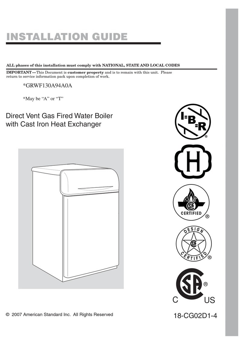
American Standard GRWF130A94A0A User manual

American Standard

American Standard GRWF130A94A0A User manual

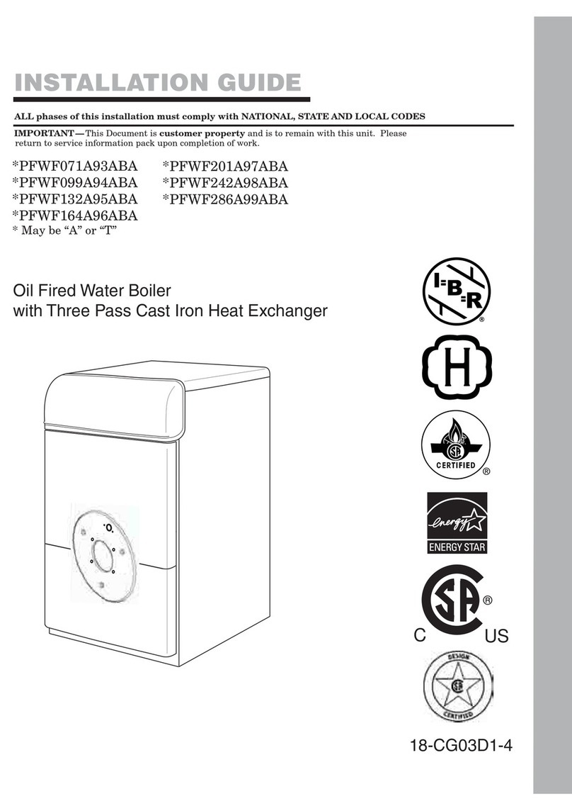
American Standard PFWF071A93ABA User manual

American Standard

American Standard PFWF071A93ABA User manual

Popular Boiler manuals by other brands

MHG Heating procon gwb smartline installer and user manual

MHG Heating

MHG Heating procon gwb smartline installer and user manual

Baxi Luna 3 Silver Space Operating and installation instructions

Baxi

Baxi Luna 3 Silver Space Operating and installation instructions

Bosch Worcester Greenstar CDi Conventional Series instruction manual

Bosch

Bosch Worcester Greenstar CDi Conventional Series instruction manual

Joannes EPOCA 25-29 NS Installation and maintenance manual

Joannes

Joannes EPOCA 25-29 NS Installation and maintenance manual

Maktek 25 MKK-S INSTALLATION USE AND MAINTAINENCE GUIDE

Maktek

Maktek 25 MKK-S INSTALLATION USE AND MAINTAINENCE GUIDE

Vaillant ecoTEC plus 806 VU GB 806/5-5 Installation and maintenance instructions

Vaillant

Vaillant ecoTEC plus 806 VU GB 806/5-5 Installation and maintenance instructions

E.C.A. KRONOS KR 24 HM Installation and user manual

E.C.A.

E.C.A. KRONOS KR 24 HM Installation and user manual

Immergas Victrix Superior 32 X 2 ERP Instruction and warning book

Immergas

Immergas Victrix Superior 32 X 2 ERP Instruction and warning book

Ferroli BLUEHELIX PRO RRT 32 C INSTRUCTIONS FOR USE, INSTALLATION AND MAINTENENCE

Ferroli

Ferroli BLUEHELIX PRO RRT 32 C INSTRUCTIONS FOR USE, INSTALLATION AND MAINTENENCE

Grant Vortex Boilerhouse Combi Installation, commissioning & maintenance instructions

Grant

Grant Vortex Boilerhouse Combi Installation, commissioning & maintenance instructions

HydroTherm HVX Installation and operating instructions

HydroTherm

HydroTherm HVX Installation and operating instructions

Riello TAU 350 N INSTALLATION, TECHNICAL ASSISTANCE SERVICE AND SYSTEM MANAGEMENT MANUAL

Riello

Riello TAU 350 N INSTALLATION, TECHNICAL ASSISTANCE SERVICE AND SYSTEM MANAGEMENT MANUAL

Sime MURELLE HM ErP Series manual

Sime

Sime MURELLE HM ErP Series manual

Dunkirk DKVLT-050 Installation, operation & maintenance manual

Dunkirk

Dunkirk DKVLT-050 Installation, operation & maintenance manual

Laars LMH user manual

Laars

Laars LMH user manual

Zip Hydroboil HS010 Installation and operating instructions

Zip

Zip Hydroboil HS010 Installation and operating instructions

elco THISION L PLUS operating manual

elco

elco THISION L PLUS operating manual

gassero Wallcon X-treme 67 Installation and user manual

gassero

gassero Wallcon X-treme 67 Installation and user manual

manuals.online logo
manuals.online logoBrands
  • About & Mission
  • Contact us
  • Privacy Policy
  • Terms and Conditions

Copyright 2025 Manuals.Online. All Rights Reserved.