manuals.online logo
Brands
  1. Home
  2. •
  3. Brands
  4. •
  5. American
  6. •
  7. Outdoor Cart
  8. •
  9. American TIM-390-A1 User manual

American TIM-390-A1 User manual

TIM-390-A1
Oil Dispensing Cart
Instruction Manual
Inlet Air Pressure
Operation Pressure
Reservoir Capacity
115 PSI Maximum
100 PSI Maximum
23.75 Gallons TIM-390-INST
20190129
CHARGING THE DISPENSER WITH AIR
1. Regulate the air supply hose that you are using to charge the dispensing
unit to 100 PSI maximum.
2.
in the “Closed” position. (see picture 1)
Make sure the air shuto valve (See Diagram 2) on the dispensing unit is
3. Connect the air supply hose to the air connector on the top of the tank.
4.
Diagram 2).
5. When the pressure gauge on the dispenser (see picture 3) reaches 100
the “Closed”position (see picture 1). Do not attempt to over-charge
the unit with more than 100 PSI.
6. Remove the air supply hose from the air connector on the top of the tank.
7.
thus it should always be left in the “Open” position.
8. Open the non-drip tip on the meter (see picture 5). Place the tip of the meter
into a container used for waste oil. Pull the trigger on the digital meter to
system.
9. Close the non-drip tip on the meter (see picture 5).
10. Reset the digital meter to zero.
11. The unit is now ready for dispensing. When the oil delivery rate falls below
an acceptable level, recharge the air pressure in the unit by repeating steps
1-7 above.
SERVICING THE DISPENSER
1. If you have any questions, call American Lubrication Equipment Corporation at 410-252-9300 before
you begin to service this unit. Only authorized service centers can perform warranty work on the
units. Any work done by unauthorized service centers will void the warranty.
2. Make sure that the unit is not connected to an air hose and that the air connector on the unit is not
obstructed before servicing.
3.
eyes or anything else in the way of the air connector while draining the air pressure. The air gauge
picture 1
picture 2
picture 3
picture 4
picture 5
Turn the air shuto valve to the ”Open” position (see picture 2 and
PSI, turn the air shuto valve (See Diagram 2) on the dispensing unit to
Make sure that the oil shuto valve (See Diagram 2) is in the “Open”
position (see picture 4). The oil shuto valve is for servicing the unit only,
4.
5. It is now safe to perform service work on the unit.
MOBILE OIL DISPENSE UNIT OPERATION INSTRUCTIONS
This unit allows for oil dispense directly from the pressurized container through a digital meter at approxi-
mately 8 quarts per minute. The unit uses air pressure to dispense oils. The dispenser holds 23 gallons and is
WARNINGS
-
cap.
Do not overcharge the unit. 100 PSI is the maximum working pressure. Overcharging the unit can result in
serious injury.
-
not be adjusted. If the valve becomes damaged, discontinue using the unit and call for service immediately.
Failure to do so could cause serious injury.
Do not run the unit dry. The digital meter will read air coming through the dispense hose. Consistently moni-
tor the oil level via the sight gauge located on the side of the unit.
recommended that the air source has a drop-leg water trap.
FILLING THE DISPENSER WITH OIL
1. Make sure that the unit is not connected to an air supply source and that the air connector on the
unit is not obstructed.
2.
else in the way of the air connector when the air pressure is draining. The units’ air gauge must read
3.
4.
5.
Make sure the unit is not pressurized.Turn the air shuto valve (See Diagram 2) to the ”Open”
position (see picture 2) to bleed o any pressure inside the unit. Do not place your eyes or anything
”0” before attempting to remove the ll cap.
Diagram 1
Sight Gauge
Oil Fill Funnel
Valve
Air Filter
Air Connector
Valve
Position D,
TIM-1501-88
(90 Degree Union 1/2" NPT)
Position #21
Not Available
Position #22,
TIM-317-43
(Ball Valve)
Position E,
TIM-1404-44
(Straight Union)
Position C,
TIM-212-1
(Adapter)
Position A,
23902-210
(Quick Coupler)
Valve
Fill Cap
Air Gauge
Diagram 2
TIM-390-A1 Self-Contained Oil Dispenser
Note: For early production TIM-390-A1 models with two xed wheels and two caster wheels,
for replacement xed wheels, order part number: TIM-317-2 (sold as pair).
Note: sight tube markings start at 3.75 gal and end at 19.5 gallon.
Position
#QTY Description Part Number
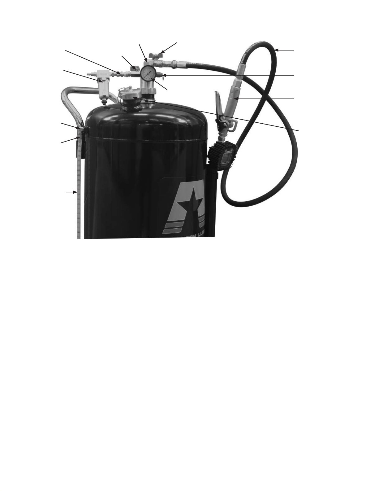
1 1 Reservoir 90L (Ver. 1.0) Not available
2 1 Round Nut w/ Collar Not available
3 1 Gauge (Thread type unknown) Not available
4 1 Seat Not available
5 1 Steel Tube Not available
6 1 O-ring (42.5 x 2.65) Not available
7 1 Handle w/ hook TIM-317-20
8 2 Screw w/ Chamfered End TIM-317-17
9 4 Acorn Nut TIM-317-6
10 4 Spring Washer TIM-317-41
11 4 Plain Washer TIM-317-5
12 2 Swivel/Caster Wheel (sold as pair) TIM-317-4
13 2 Elbow TIM-317-7
14 2 Nut TIM-317-8
15 1 Tube with Label TIM-317-9
16 1 Fill Cap TIM-390AS1-16
17 1 Gasket, Fill Cap TIM-390-GAST
18 1 Hex Head Screw Not available
19 1 Chain Not available
20 1 Steel Ring Not available
21 1 ¼” M x ¼” F Adapter Not available
22 1 ¼” M x ¼” F Ball Valve TIM-317-43
23 1 Elbow Adapter Not available
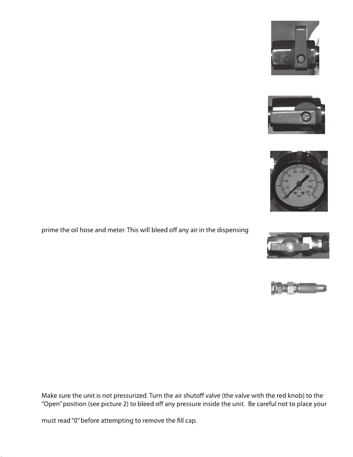
24 1 1/2" Ball Valve (1/2” FPT x ½” MPT) Not available
25 1 Safety Valve Not available
26 1 Connecting Hose(Discharge)
1/2" Hose 1/2” NPT(M) x 1/2” NPT(F) TIM-390-HOSE
27 1 Container See #30
28 1 Cap See #30
30 1 Tube (Set of #27 and #28) TIM-390-30
32 1 Funnel Not available
A1 Quick Coupler (¼” MPT) 23902-210
B1 Air Filter (¼” FPT x ¼” FPT) F-100
C1 Straight union adapter (1/4" NPT) TIM-1404-44
1 TIM-1501-88
E
D
1 1/4" (M) x 1/4" (M) adapter TIM-212-1
1 Manual TIM-390-INST
F1 Digital Meter Control Handle TIM-601-FM
90 Degree Union Adapter (1/2" NPT)
#21, adapter,
not available
#16 ll cap,
TIM-390AS1-16
#17, gasket ll cap,
TIM-390-GAST
#26, TIM-390-HOSE
#15 tube with
label, TIM-317-9
#14, nut
TIM-317-8
#13, elbow,
TIM-317-7
#3, gauge,
not available Position F,
TIM-601-FM
#25, safety valve,
not available
#22, Ball valve,
TIM-317-43
#24, ball valve,
not available
#23, elbow,
not available
Position B,
Filter, F-100

Popular Outdoor Cart manuals by other brands

SAW TRAX yel-Low Safety Dolly instruction manual

SAW TRAX

SAW TRAX yel-Low Safety Dolly instruction manual

Opti-Med JM025-009 user manual

Opti-Med

Opti-Med JM025-009 user manual

Metro DataVac Flo Series Operation manual

Metro DataVac

Metro DataVac Flo Series Operation manual

VEVOR GT0709 manual

VEVOR

VEVOR GT0709 manual

Vestil CYHT-1 manual

Vestil

Vestil CYHT-1 manual

Gill 4210 Assembly instructions

Gill

Gill 4210 Assembly instructions

DECK DOLLY JD4 5 Series Assembly instructions

DECK DOLLY

DECK DOLLY JD4 5 Series Assembly instructions

Copernicus PDR05 Assembly guide

Copernicus

Copernicus PDR05 Assembly guide

VonHaus 2515213 instructions

VonHaus

VonHaus 2515213 instructions

Balt 27529 Assembly instructions

Balt

Balt 27529 Assembly instructions

Cornwell Tools CRCS2DRW operating instructions

Cornwell Tools

Cornwell Tools CRCS2DRW operating instructions

Vestil AIR-800-D instruction manual

Vestil

Vestil AIR-800-D instruction manual

Montezuma M700502TC owner's manual

Montezuma

Montezuma M700502TC owner's manual

Gorilla Carts GCG-900 manual

Gorilla Carts

Gorilla Carts GCG-900 manual

Spectrum Industries Impression 30 Imaging Laptop Cart owner's manual

Spectrum Industries

Spectrum Industries Impression 30 Imaging Laptop Cart owner's manual

Lumag MD-500EK user manual

Lumag

Lumag MD-500EK user manual

Sunjoy L-PS158PST-5 Assembly instructions

Sunjoy

Sunjoy L-PS158PST-5 Assembly instructions

brent Corner Auger 1080 Operator's Manual / Parts Catalogue

brent

brent Corner Auger 1080 Operator's Manual / Parts Catalogue

manuals.online logo
manuals.online logoBrands
  • About & Mission
  • Contact us
  • Privacy Policy
  • Terms and Conditions

Copyright 2025 Manuals.Online. All Rights Reserved.