/~LATION
/'"
TheAL-80Aventilationsystem has been designed and tested
to maintain tube seal temperatures safely below the tube
manufacturer's ratingwhen operated withinour guidelines.
To insure proper ventilationinyour installation,observe the
following:
1. Do not block or restrict the ventilation holes in the
cover.
2. The exhaust airflowis over 50 CFM.Donot "assist" the
air flowunless the fan used exceeds the AL-80Ablower
CFM by a factor of 2:1.
3. Do not mount additional fans on the AL-80Acabinet.
4. The exhaust air willbecome quite warm at high
power levels. Do not place any heat sensitive objects
in the exhaust air stream.
POWER CONNECTIONS
The AL-80Aissupplied with a NEMA 5-15Pplugfor 117VAC
operation. The AL-80A can be modified for 234 VAGopera-
tion. Ifyoudesire to makethis modification,twojumper wires
must be movedto new locations on the terminal block. (see
illustration below) The terminal block is located on the left
side of the rear panel.
The wiring betweenthe fuse box andthe amplifier AC. outlet
must be No. 12 gauge or larger in order to supply the cur-
rent required (15 amperes) without a significant drop in line
voltage. The 117V outlet should be fused for 20 amperes.
~.
~I~
IOO
I I
I!I
117 VOLT OPERATION 234 VOLT OPERATION
~
ALC
Use a shielded audio-type cable to connect the 0-20 volt
negative ALC voltage to the transmitter ALC input. Consult
the transmitter manual for proper connection details. The
amplifier must be properly tuned on CW before adjusting the
ALC. '
Proper adjustment is achieved as follows:
1. Set the MULTIMETER switch to the PO position.
2. Set the transmitter audio control about 20% higher
than normal.
3. Speak into the microphone in a normal tone of
voice and observe the reading on the 0-2000 R.F.
Watts scale.
4. Adjust the ALC ADJ control on the rear panel until the
amplifier is not clipping on an RF scope.
5. If an RF scope is not available, adjust the ALC control so
the audio peaks do not exceed the single tone output of
1000 watts.
METERING FUNCTIONS
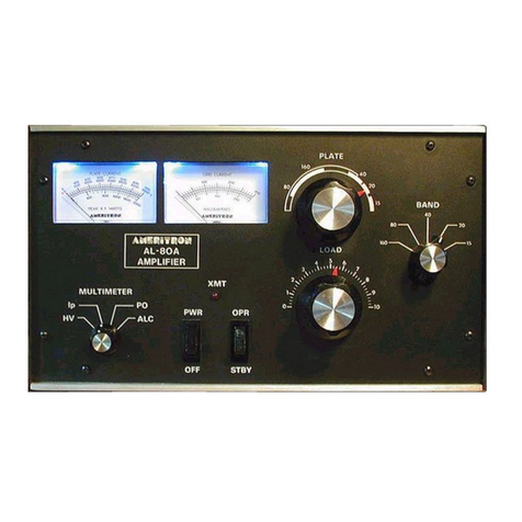
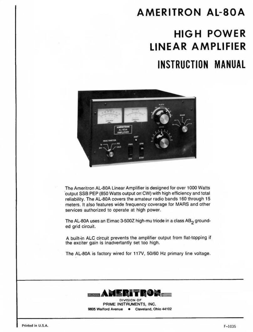
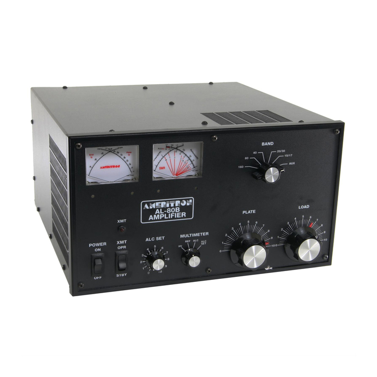
The AL-80Ahas two illuminated panel meters.The Grid Cur-
rent meter provides a continous reading of grid current. This
is an exclusive feature of Ameritron amplifiers. Grid current
will indicate proper operation of the amplifier better than any
other parameter. Do not exceed 200 mA on this meter dur-
ing operation of the amplifier. The other meter reads Plate
Voltage (HV), Plate Current (Ip), Peak R.F. Watts (PO) and
ALC. The functions are explained as follows:
PLATE VOLTAGE (HV): Read D.C. Plate Voltage on the
0-3500 Volt scale. This scale is 100 volts per division. Nor-
mal voltages are 3100 volts no load, 2700 volts full load.
PLATECURRENT(Ip):Read PlateCurrent onthe 0-700mA
scale. This scale is 20 mA per division. The average
operating current rating of the 3-500z is 400 mA maximum.
PEAK R.F. WATTS (PO): Read Peak R.F. Watts on the
0-2000 scale. The scale has 50 watt divisions below 1000
watts and 100 watt divisions above 1000 watts.
ALC: In this position the meter indicates the ALC detector
voltage. It provides a relative drive level indication of 200
watts full scale. The approximate drive level (average, not
PEP)can be estimated by dividing the Peak R.F. Wattsscale
by 10.
IMPORT ANT
Do not make any modifications to the AL-80A cir-
cuit before checking with our engineering staff.
Improper changes may damage the AL-80A'and void
the warranty.
1
~,- ......
