AmeriWater HEF CWST User manual
Other AmeriWater Water System manuals

AmeriWater
AmeriWater OH 45414 Instruction Manual

AmeriWater
AmeriWater Central Sterile ROS Manual

AmeriWater
AmeriWater VARIABLE SPEED PUMP SYSTEM Manual

AmeriWater
AmeriWater 00HRO57600 Manual

AmeriWater
AmeriWater V125DTH Manual
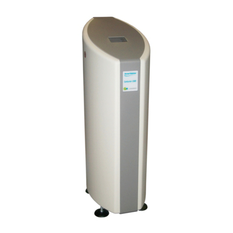
AmeriWater
AmeriWater CENTURION 1500+ User manual

AmeriWater
AmeriWater OZONE Manual

AmeriWater
AmeriWater Central Sterile RO2 Manual

AmeriWater
AmeriWater Bicarb User manual

AmeriWater
AmeriWater MRO3 Manual

AmeriWater
AmeriWater Central Sterile RO3 Manual
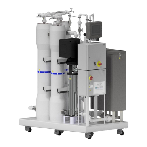
AmeriWater
AmeriWater MediQA Setup guide

AmeriWater
AmeriWater Central Sterile RO3X Manual
AmeriWater
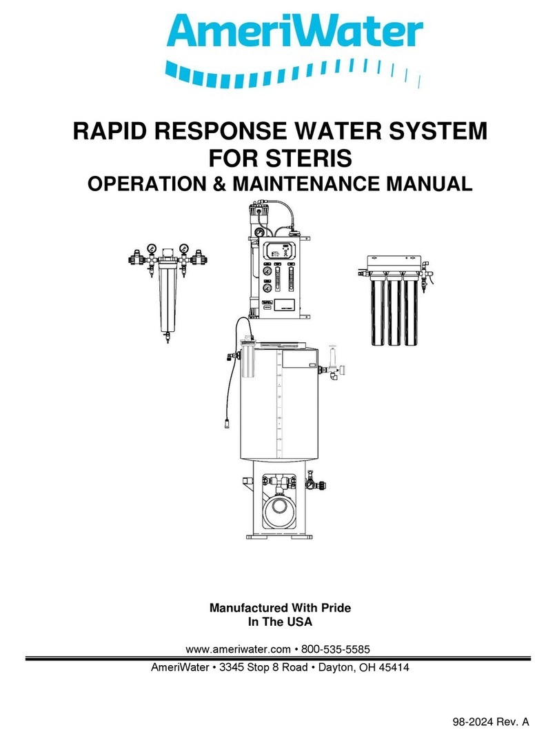
AmeriWater RAPID RESPONSE Manual
AmeriWater
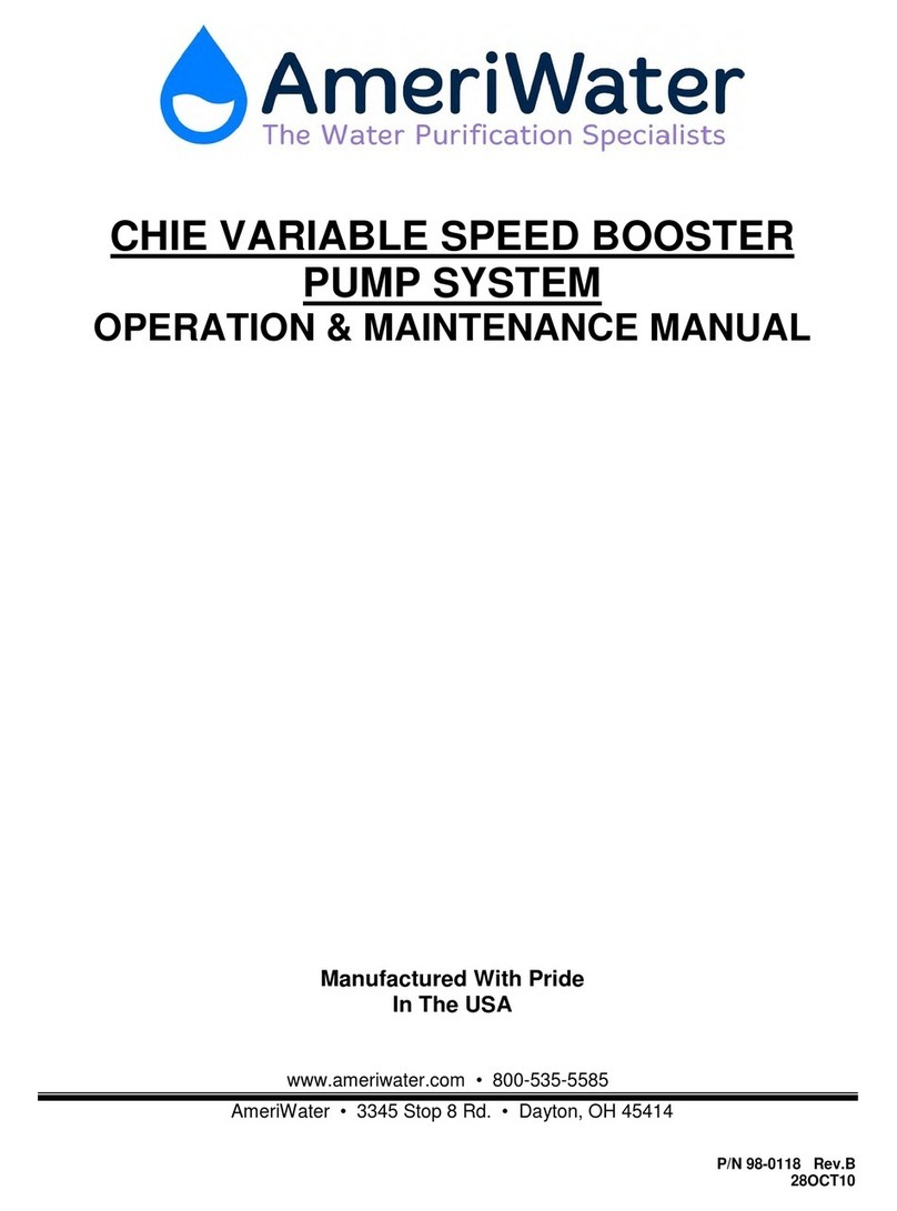
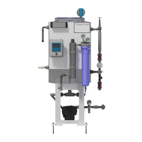
AmeriWater CHIE VARIABLE SPEED BOOSTER PUMP SYSTEM Manual
AmeriWater
AmeriWater 00HC-4090 Manual
AmeriWater
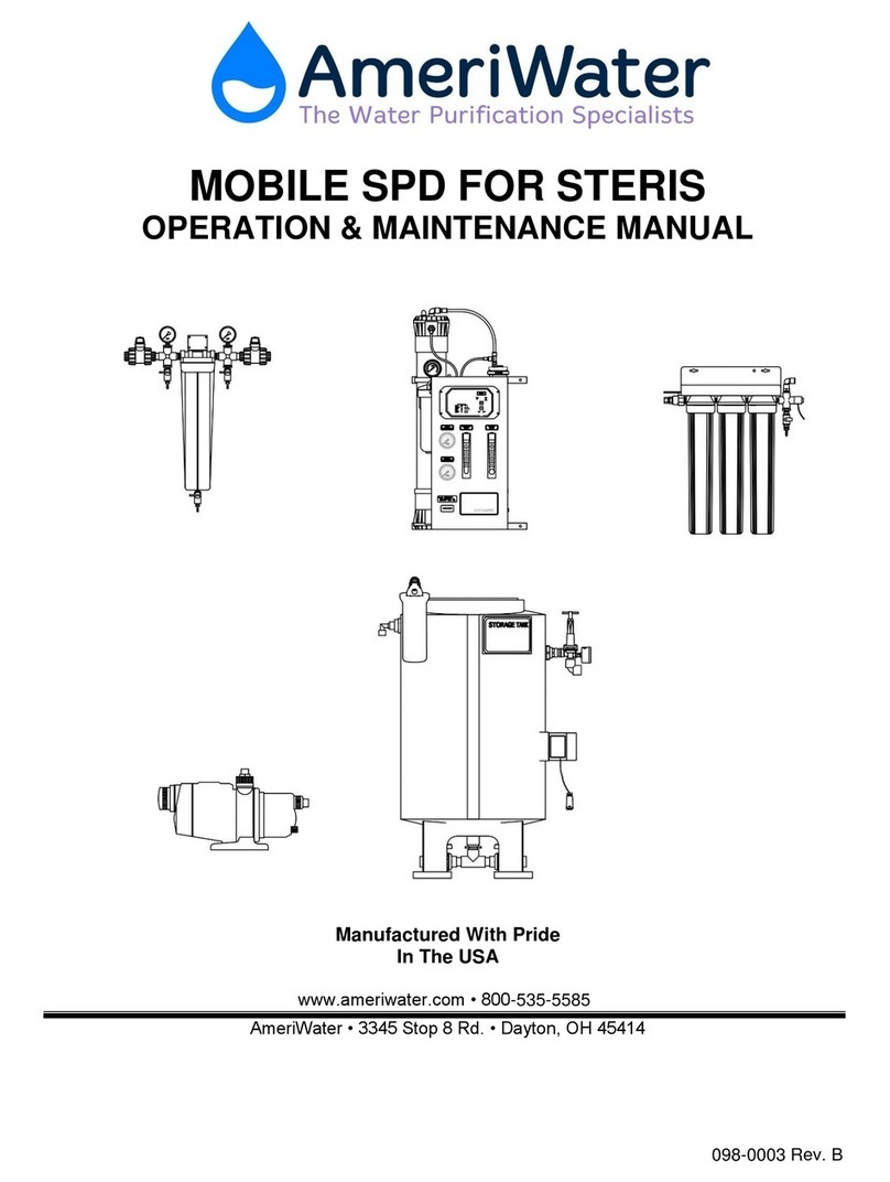
AmeriWater SPD Manual

AmeriWater
AmeriWater GRUNDFOS CHI Manual
AmeriWater
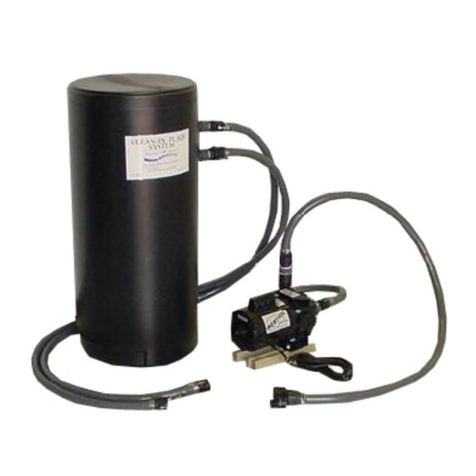
AmeriWater CLEAN IN PLACE CIP2 User manual

AmeriWater
AmeriWater MRO3Z Instruction manual
Popular Water System manuals by other brands

Accu-Tab
Accu-Tab PowerBase 3070AT Installation and operating instructions

Energy Plus
Energy Plus VTS30HP Manual of installation and use

Spirotech
Spirotech SPIROVENT SUPERIOR S250 user manual

Culligan
Culligan Aqua-Cleer Aqua-Cleer Advanced Drinking Water... owner's guide

A.O. Smith
A.O. Smith Dura-Max AJH - 1000A - P instruction manual

Microline
Microline T.F.C.-4 Installation, operation & service manual

Eureka Forbes
Eureka Forbes Aquaguard Select user manual

Cetetherm
Cetetherm AquaEfficiency Quick installation guide

CB Tech
CB Tech CB-VOC installation guide

Vaillant
Vaillant auroFLOW plus VPM 15 D Installation and maintenance instructions

resideo
resideo Braukmann HS10S installation instructions

Gude
Gude INOX 100/24 manual

Mono
Mono Eco 1-60 Installation, operation and maintenance instructions

SpectraPure
SpectraPure Drinking Water Kit instructions

HydroCare
HydroCare Dual Action Installation, use & care guide

Alpha
Alpha SolarSmart 150 Installation and servicing instructions

TA
TA FRISTAR3 operating manual

GÜDE
GÜDE HWA 800 K manual
