be necessary in milder weather, although monthly
cleanings may be enough in the coldest months.
Contact your local authority for information on how to
handle a chimney fire, and have a clearly-understood
plan to handle a chimney fire.
ASH DISPOSAL
Regularly inspect the ash build-up in your unit and
remove as necessary. Ashes can be removed from the
unit with a shovel and put them into the ash pan.
Caution: Never remove red-hot ashes from the
appliance; allow ashes to cool before dropping into
the ash pan. Ashes should be placed in a metal
container with an airtight lid. The ashes should be
placed on a noncombustible surface and completely
away from any combustible materials. The ashes
should remain in the airtight container until they
have completely cooled.
IMPORTANT: HELPFUL HINTS
AND TIPS WORTH REVIEWING
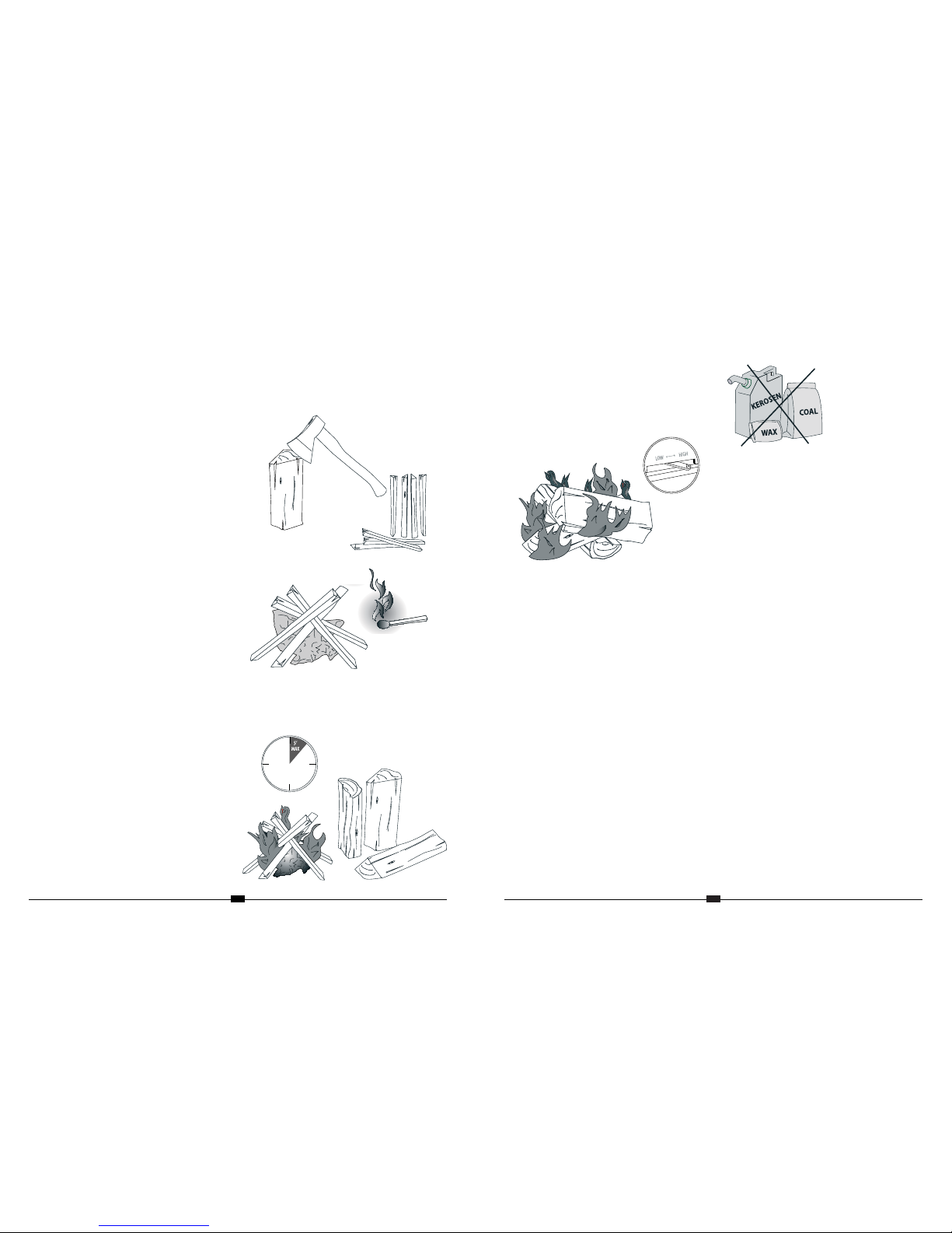
1. What is the correct way to start a fire?
• You will need small pieces of dry wood (kindling)
and paper. Use only newspaper or paper that has
not been coated or that has had materials glued or
applied to it. Never use coated or colored paper (such
as advertising flyers).
• Open the door of the wood stove.
• Crumple several pieces of paper, and place them in
the center of the firebox, directly on the firebricks of
the stove. Never use a grate to elevate the fire.
• Place small pieces of dry wood (kindling) over the
paper in the form of a“teepee.” This allows for good air
circulation, which is important for good combustion.
• Light the crumpled paper in two or three different
locations. NOTE: It is important to heat the air in the
stovepipe for draft to begin.
• Fully open the air control of the wood stove, and
close the door until it is just slightly open, allowing
for air to be introduced into the firebox. Never leave
the door fully open, as sparks from the kindling may
occur, causing injury. As the fire begins to burn the
kindling, some additional kindling may be needed to
sustain the fire. DO NOT add more paper after the fire
has started.
• Once the kindling has begun to burn, start adding
some small pieces of seasoned, dry firewood. NOTE:
Adding large pieces at the early stages will only serve
to smother the fire. Continue adding small pieces of
seasoned, dry firewood, keeping the door slightly
open until each piece starts to ignite. Remember to
always open the door slowly when placing wood into
the fire.
• Once the wood has started to ignite and the smoke
has reduced, close the stove door fully. (Reduction
of smoke is a good indication that the draft in the
chimney has begun, and good combustion is now
possible.) Larger pieces of seasoned, dry firewood can
now be added when there is sufficient space in the
firebox. Adjust the air control setting to your desired
setting.
• NOTE: The lower the air control setting, the longer
the burn time of the firewood.
2. How to reload your fireplace?
• Open the door and slide the ash tray outwards to
catch live coals that may fall. Poke the live coals with a
fire hook to remove the ash and place the new wood
on top of these coals.
• Never open the door while the fire is burning
vigorously. Wait until the fire calms down.
• Slide the air control lever to“HIGH”for a few minutes.
Once the flames are vigorous, move the air control
lever towards“LOW” to reduce air intake and achieve
the desired heat.
3. What type of wood is best to use as firewood?
• Dry, seasoned hardwood should be used. Avoid
green, unseasoned wood. Green wood, besides
burning at only 60% of the fuel value of dry seasoned
wood, will deposit creosote on the inside of the stove
and along to inside of the chimney.
4. What does dry, seasoned wood mean, and what
is considered to be hardwood?
• Wood that has been dried for a period of one year
in a well-ventilated and sheltered area is considered
dry, seasoned wood. Hardwoods generally come
from slow-growth trees, such as Oak or Fir. Softwoods
generally come from fast-growth trees, such as Pine
or Spruce.
5. Will following the steps listed above result in a
perfect fire every time?
• A good answer would be “most of the time.” There
are many variables that can affect your rate of success
when starting a fire, and experience will teach you
how to deal with the variables. This section of the
manual will cover some of the variables that can
affect a fire, and time and patience will contribute to
your ability to start a good fire consistently.
6. Why can’t I get the fire lit?
• Damp or wet wood and poor draft are the main
reasons for poor results when starting a fire.
Remember to always use dry, seasoned wood for your
fire. Even wood that has been dried (seasoned) for a
long period of time will be difficult to light if it has
gotten wet.
7. Why is there always a large quantity of thick
black smoke in the firebox?
• A large quantity of thick black smoke in the firebox
is a possible indication that you have poor draft.
8. Is it normal for soot to cover the glass at the
beginning of a fire?
• This stove has been built with an air wash system
that will help keep the glass clear when the firebox
has reached a good operating temperature, and
also has a good draft. Cold firebox temperature and
poor draft cause soot to form on the glass. Once the
firebox temperature and the draft increase, the soot
should burn off.
9. What is “draft?”
• Draft is the ability of the chimney to exhaust draw
by-products produced during the normal process of
combustion.
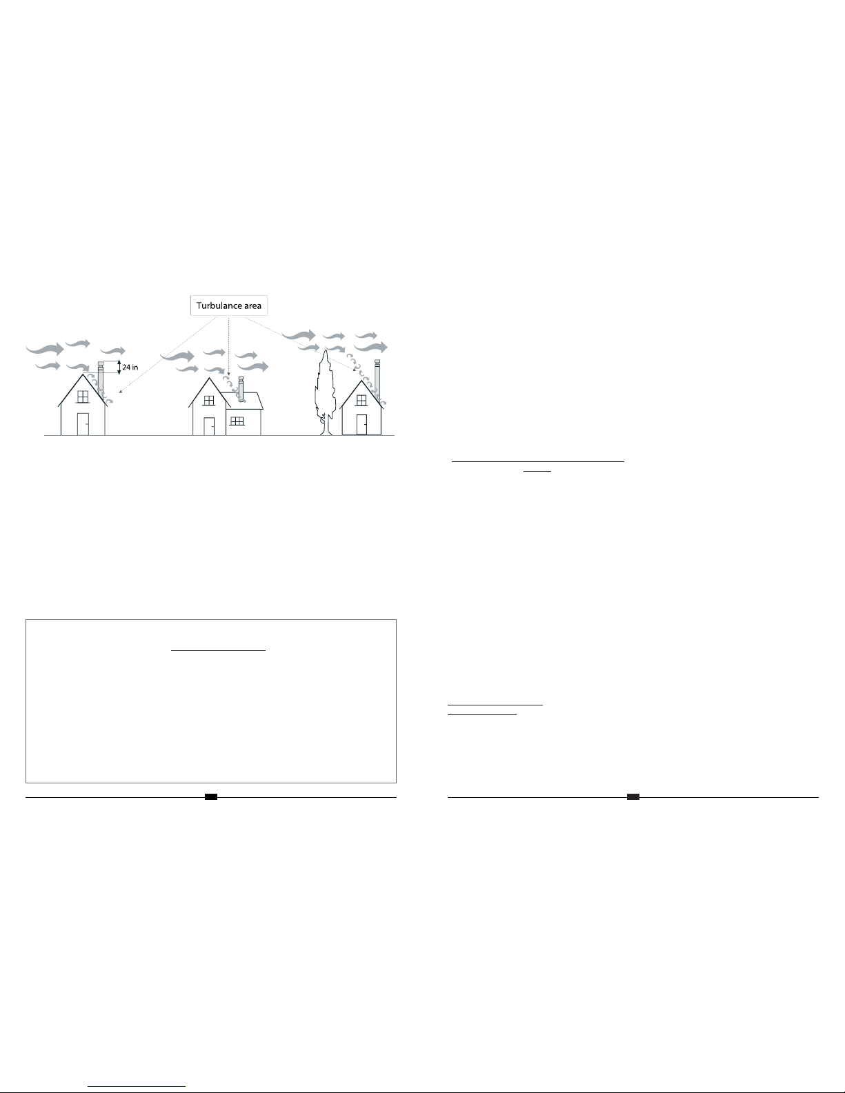
10. What can cause a poor draft?
• If wind collides with an obstacle, there will be
turbulence that can cause smoke to blow back
down the flue (down draft). To correct this situation,
increase the length of the flue so that it projects over
the turbulence area.
• Thereare severalcommonfactorsthatcan contribute
to poor draft:
A. Atmospheric Pressure and Air Supply
Atmospheric pressure affecting the draft from a
chimney can be outside the home, inside the home,
or both. Outside the home, a high-pressure (clear
and cool) day generally creates a better draft in the
chimney than a low-pressure (overcast and damp)
day. Inside the home, household appliances, such
as forced-air furnaces or clothes dryers, compete
for air, often resulting in inadequate amounts of air
available to fuel a fire and creating a condition known
as negative pressure. Extreme conditions of negative
pressure can cause the combustion by-products to
be drawn from the chimney and into the house. This
condition is commonly known as“down drafting.”
There are several factors that can affect the amount
of air available in the home. Increased amounts of
insulation, vinyl windows, extra caulking in various
places and door seals can all keep heat in, but may
also make a home too airtight. If you are in doubt as
to whether or not there is sufficient air in your home
for your stove, refrain from using those appliances
known to consume air when possible, or open a door
or a window to allow some air to enter the home.
B. Environmental Conditions
High trees, a low-lying house location (such as in a
valley), tall buildings or structures surrounding your
house and even windy conditions can cause pool
draft or down drafting.
16 17