Ametek Drexelbrook DR7000 Series Wiring diagram

Radar Level Instrument for 2-wire control systems
(liquids)
Supplementary Instructions for ATEX applications
Supplementary Instructions for ATEX applicationsSupplementary Instructions for ATEX applications
Supplementary Instructions for ATEX applications
DR7000 SERIES
DR7000 SERIESDR7000 SERIES
DR7000 SERIES Supplementary instructions
Supplementary instructionsSupplementary instructions
Supplementary instructions
© AMETEK Drexelbrook - EDO 11-10-112, DR7000-LM ATEX, Issue #2

CONTENTS
2
www.drexelbrook.comEDO 11-10-112, DR7000-LM ATEX, Issue #2
DR7000 SERIES
1 General safety information 4
1.1 Scope of the document..................................................................................................... 4
1.2 Device description ............................................................................................................ 4
1.3 Standards and approvals.................................................................................................. 4
1.4 Device categories ............................................................................................................. 5
1.4.1 Ex ia / Ex iaD-approved devices.............................................................................................. 5
1.4.2 Ex d[ia] / Ex tD[iaD]-approved devices ................................................................................... 5
1.4.3 Ex nA devices .......................................................................................................................... 5
1.4.4 Definitions of device categories.............................................................................................. 5
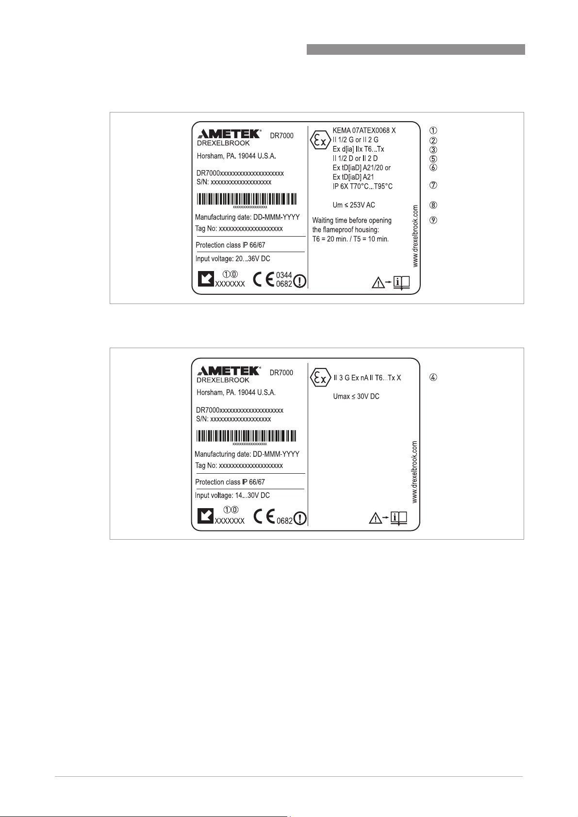
1.5 ATEX nameplates.............................................................................................................. 6
2 Installation 8
2.1 Precautions....................................................................................................................... 8
2.1.1 General notes.......................................................................................................................... 8
2.1.2 Electrostatic discharge........................................................................................................... 8
2.1.3 Special conditions ................................................................................................................... 9
2.1.4 Optional purging system......................................................................................................... 9
2.2 Operating conditions ...................................................................................................... 10
2.2.1 Ambient and flange temperature ......................................................................................... 10
2.2.2 Maximum surface temperature of the housing ................................................................... 13
2.2.3 Process pressure.................................................................................................................. 13
3 Electrical connections 14
3.1 General notes ................................................................................................................. 14
3.2 Terminal compartment .................................................................................................. 14
3.2.1 How to open the terminal compartment .............................................................................. 14
3.2.2 How to close the terminal compartment ............................................................................. 15
3.3 Terminal tightening capacity.......................................................................................... 15
3.4 Equipotential bonding system........................................................................................ 15
3.5 Ex ia / Ex iaD equipment................................................................................................. 15
3.5.1 How to connect the electrical cables ................................................................................... 15
3.5.2 Maximum intrinsically-safe values for the electrical circuit............................................... 16
3.5.3 Supply voltage ....................................................................................................................... 16
3.5.4 Electrical schema ................................................................................................................. 17
3.6 Ex d[ia] / Ex tD[iaD] equipment ...................................................................................... 18
3.6.1 General notes........................................................................................................................ 18
3.6.2 How to connect the electrical cables ................................................................................... 18
3.6.3 Supply voltage ....................................................................................................................... 19
3.6.4 Electrical schema ................................................................................................................. 19
3.7 Ex nA equipment............................................................................................................. 20
3.7.1 How to connect the electrical cables ................................................................................... 20
3.7.2 Supply voltage ....................................................................................................................... 20
3.7.3 Electrical schema ................................................................................................................. 20
4 Start-up 21

CONTENTS
3 www.drexelbrook.co EDO 11-10-112, DR7000-LM ATEX, Issue #2
DR7000 SERIES
5 Service 22
5.1 Periodic maintenance..................................................................................................... 22
5.2 Keep the device clean..................................................................................................... 22
5.3 Returning the device to the manufacturer..................................................................... 22
5.3.1 General information.............................................................................................................. 22
5.3.2 Form (for copying) to accompany a returned device............................................................ 23

GENERAL SAFETY INFORMATION 1
4
DR7000 SERIES
www.drexelbrook.comEDO 11-10-112, DR7000-LM ATEX, Issue #2
1.1 Scope of the document
These instructions are applicable only to the explosion-protection version of the radar level
transmitter. For all other data, use the Quick Start and Handbook. If you do not have these
documents, please contact the nearest office or download them from the manufacturer's
internet site.
1.2 Device description
This device is a 2-wire level transmitter that uses FMCW (Frequency-Modulated Continuous
Wave) radar technology. It measures level, volume, distance to surface and reflectivity of liquids,
pastes and slurries.It is suitable for installation on storage tanks, process tanks and stilling
wells. Measurements are displayed via a DTM (device type manager) for remote communication
or on an optional integrated display screen with wizard-driven setup and online help functions.
The level transmitter is approved for use in potentially explosive atmospheres when equipped
with the appropriate options.
1.3 Standards and approvals
The certificate is given on the CD-ROM supplied with the device. You can also download the
certificate from our internet site.
INFORMATION!
The information in these supplementary instructions only contains the data applicable to
explosion protection. The technical data for the non-Ex version in the Handbook shall be valid in
its current version, provided that it is not rendered invalid or replaced by these supplementary
instructions.
WARNING!
Installation, commissioning and maintenance may only be carried out by "Personnel trained in
explosion protection".
DANGER!
In compliance with European Directive 94/9/EC (ATEX 100a), the ATEX version of the device
described in these Supplementary Instructions conforms to European Standards EN 60079-
0:2006, EN 60079-1:2007, EN 60079-11:2007, EN 60079-15:2005, EN 60079-26:2007, EN 60079-
27:2008, EN 61241-0:2006, EN 61241-1:2004 and EN 61241-11:2006. The Ex ia / Ex iaD and
Ex d[ia] / Ex tD[iaD] versions are certified for use in hazardous areas by the KEMA Quality B.V.
under KEMA 07ATEX0068 X. The Ex nA version is certified for use in zone 2 under our sole
responsibility. For more data, refer to the manufacturer's declaration given on the CD-ROM
supplied with the device. You can also download the manufacturer's declaration from our
internet site.
WARNING!
Carefully read the ATEX approval certificate. Obey the boundary conditions.

1GENERAL SAFETY INFORMATION
5
DR7000 SERIES
www.drexelbrook.com EDO 11-10-112, DR7000-LM ATEX, Issue #2
1.4 Device categories
1.4.1 Ex ia / Ex iaD-approved devices
These devices are suitable for use in potentially explosive atmospheres of all flammable
substances in Gas Groups IIA, IIB and IIC. The Ex ia-approved device is certified for applications
requiring Category 1 G (gases, vapours or mists), 1/2 G or 2 G equipment when fitted with the
appropriate options. The Ex iaD-approved device is certified for applications requiring Category
1 D (dust), 1/2 D or 2 D equipment when fitted with the appropriate options.
1.4.2 Ex d[ia] / Ex tD[iaD]-approved devices
These devices are suitable for use in potentially explosive atmospheres of all flammable
substances in Gas Groups IIA, IIB and IIC. The Ex d[ia]-approved device is certified for
applications requiring Category 1/2 G (gases, vapours or mists) or 2 G equipment when fitted
with the appropriate options. The Ex tD[iaD]-approved device is certified for applications
requiring Category 1/2 D (dust) or 2 D equipment when fitted with the appropriate options.
1.4.3 Ex nA devices
The Ex nA version of this device is suitable for use in potentially explosive atmospheres of all
flammable substances in Gas Group II. It is designed for applications requiring Category 3 G
equipment when fitted with the appropriate options.
1.4.4 Definitions of device categories
Category 1
Category 1Category 1
Category 1
The device is installed in hazardous areas requiring Category 1 G or 1 D equipment.
Category 1/2
Category 1/2Category 1/2
Category 1/2
The signal converter is installed in hazardous areas requiring Category 2 G or 2 D equipment.
The probe is installed in hazardous areas requiring Category 1 G or 1 D equipment.
Category 2
Category 2Category 2
Category 2
The device is installed in hazardous areas requiring Category 2 G or 2 D equipment.
Category 2/3
Category 2/3Category 2/3
Category 2/3
The signal converter is installed in hazardous areas requiring Category 3 G or 3 D equipment.
The probe is installed in hazardous areas requiring Category 2 G or 2 D equipment.
Category 3
Category 3Category 3
Category 3
The device is installed in hazardous areas requiring Category 3 G or 3 D equipment.
INFORMATION!
These devices can also be used for applications requiring Category 2/3 or 3 equipment.
INFORMATION!
These devices can also be used for applications requiring Category 2/3 or 3 equipment.

GENERAL SAFETY INFORMATION 1
6
DR7000 SERIES
www.drexelbrook.comEDO 11-10-112, DR7000-LM ATEX, Issue #2
1.5 ATEX nameplates
Figure 1-1: Ex ia / Ex iaD nameplate (4...20 mA output)
Figure 1-2: Ex ia / Ex iaD nameplate (PROFIBUS PA or FOUNDATION™Fieldbus output)
1 ATEX certification agency code
2 Equipment category (explosive atmosphere - gas)
3 Types of device protection including approved Gas Groups (IIA, IIB or IIC) and temperature classes (T6...T3)
4 Equipment category (explosive atmosphere - dust)
5 Types of device protection (explosive atmosphere - dust)
6 Degree of ingress protection (if fitted with the appropriate cable glands) and maximum surface temperature
7 Intrinsically-safe circuit data
8 Cable entry type and size (Aluminium housing: M26×1.5, M20×1.5, ½NPT or G ½; Stainless steel housing: M25×1.5,
M20×1.5, ½NPT or G ½)
!

1GENERAL SAFETY INFORMATION
7
DR7000 SERIES
www.drexelbrook.com EDO 11-10-112, DR7000-LM ATEX, Issue #2
Figure 1-3: Ex d[ia] / Ex tD[iaD] nameplate (4...20 mA output)
Figure 1-4: Ex nA nameplate (4...20 mA output)
1 ATEX certification agency code
2 Equipment category (explosive atmosphere - gas)
3 Types of device protection including approved Gas Groups (IIA, IIB or IIC) and temperature classes (T6...T3)
4 Equipment category (explosive atmosphere - gas), types of device protection including approved Gas Groups (IIA, IIB
or IIC) and temperature classes (T6...T3)
5 Equipment category (explosive atmosphere - dust)
6 Types of device protection (explosive atmosphere - dust)
7 Degree of ingress protection (if fitted with the appropriate cable glands) and maximum surface temperature
8 Maximum voltage in accordance with EN 60079-0
9 Minimum waiting time after power-off before it is safe to open the terminal compartment
10 Cable entry type and size (Aluminium housing: M26×1.5, M20×1.5, ½NPT or G ½; Stainless steel housing: M25×1.5,
M20×1.5, ½NPT or G ½)

INSTALLATION 2
8
DR7000 SERIES
www.drexelbrook.comEDO 11-10-112, DR7000-LM ATEX, Issue #2
2.1 Precautions
2.1.1 General notes
2.1.2 Electrostatic discharge
Take the necessary antistatic precautions if you:
•handle,
•install or
•use
the device in potentially explosive atmospheres. Do not install in a location (near to ventilation
systems, for example) where the electrostatic charge can increase.
WARNING!
When you install the device, obey the conditions in the EC-Type Examination certificate. These
conditions include:
•
The special conditions for safe use.
•
The Essential Health and Safety Requirements.
The certificate is given on the CD-ROM supplied with the device. You can also download the
certificate from our internet site.
DANGER!
This installation must agree with EN 60079-14: Explosive atmospheres - Part 14: Electrical
installations design, selection and erection and EN 61241-14: Electrical apparatus for use in the
presence of combustible dust - Part 14: Selection and installation.
DANGER!
Risk of electrostatic discharge from the blue plastic sun cover, the Drop antenna and the flange
plate protection (if the Drop antenna has this option). Make sure that all personnel and
equipment are correctly grounded.
Figure 2-1: ESD warning sticker (below the device nameplate)
1 Text: Plastic Parts
2 Text: Warning! Potential electrostatic hazard - see instructions
PLASTIC PARTS
WARNING:
POTENTIAL ELECTROSTATIC HAZARD
SEE INSTRUCTIONS
!

2INSTALLATION
9
DR7000 SERIES
www.drexelbrook.com EDO 11-10-112, DR7000-LM ATEX, Issue #2
2.1.3 Special conditions
2.1.4 Optional purging system
The purging system is supplied as an option for devices that have horn antennas.
Figure 2-2: Risk of ESD
1 Sun cover
2 Drop antenna
3 Flange plate protection (option for the Drop antenna)
WARNING!
Aluminium housing: Possible source of ignition in a potentially explosive atmosphere. The
housing is made of either aluminium alloy or stainless steel. If the device has an aluminium
alloy housing, make sure that iron/steel objects do not hit or rub against the device.
INFORMATION!
If the device is approved for operation in zone 2, the display agrees with the low-energy impact
test requirements for this certification.
Figure 2-3: Optional purging system
1 ¼NPTF purging connection (optional)

INSTALLATION 2
10
DR7000 SERIES
www.drexelbrook.comEDO 11-10-112, DR7000-LM ATEX, Issue #2
Connection and operation of the purging connection are the responsibility of the user. The
operator is also responsible for selection of a suitable fluid to purge the device.
• If the screw is removed, make sure that the installation agrees with the Ex requirements for
the purging system.
2.2 Operating conditions
The allowable ambient temperature and corresponding flange temperature range for the device
depends on the ATEX equipment category and temperature classes marked on the nameplate.
2.2.1 Ambient and flange temperature
The ATEX equipment category and temperature class give the ambient temperature and related
flange temperature ranges for the device.
Equipment category 1 G: Ex ia devices only
Equipment category 1/2 G: Ex ia and Ex d[ia] devices
INFORMATION!
If delivered with the device, the purging connection is plugged with a
¼
NPTF screw and engaged
on a minimum of 3
½
threads.
WARNING!
The gasket temperature must be in the approved limits. For more data, refer to "Pressure and
temperature ranges" in the Installation chapter of the handbook.
Temperature
class
Ambient temperature Flange temperature
4...20 mA output option PROFIBUS PA or
FOUNDATION™Fieldbus
output options
[°C] [°F] [°C] [°F] [°C] [°F]
T6 -20…+57 -4…+122 -20…+50 -4…+122 -20…+60 -4…+140
Temperature
class
Ambient temperature Flange temperature
4...20 mA output option PROFIBUS PA or
FOUNDATION™Fieldbus
output options
[°C] [°F] [°C] [°F] [°C] [°F]
T6 -40…+57 -40…+134 -40…+50 -40…+122 -20…+60 -4…+140
T5 -40…+72 -40…+161 -40…+72 -40…+161 -20…+60 -4…+140
T4 -40…+80 -40…+176 -40…+80 -40…+176 -20…+60 -4…+140

2INSTALLATION
11
DR7000 SERIES
www.drexelbrook.com EDO 11-10-112, DR7000-LM ATEX, Issue #2
Equipmentcategory2G,2/3Gor3G:
Ex ia and Ex d[ia] devices - with the 4...20 mA output option
Temperature
class
Ambient temperature Flange temperature
Hygienic antennas Drop and horn
antennas
Drop and horn
antennas with the
distance piece
[°C] [°F] [°C] [°F] [°C] [°F] [°C] [°F]
T6 -40…+57 -40…+134 -40…+57 -40…+134 -40…+57 -40…+134 -50…+60
1
-58…+140
1
-40…+50 -40…+122 -40…+47 -40…+116 -40…+51 -40…+124 -50…+85
1
-58…+185
1
T5 -40…+72 -40…+161 -40…+72 -40…+161 -40…+72 -40…+161 -50…+75
1
-58…+167
1
-40…+65 -40…+149 -40…+62 -40…+143 -40…+66 -40…+151 -50…+100
1
-58…+212
1
T4 2 -40…+80 -40…+176 -40…+80 -40…+176 -40…+80 -40…+176 -50…+85
1
-58…+185
1
-40…+76 -40…+169 -40…+74 -40…+165 -40…+79 -40…+174 -50…+100
1
-58…+212
1
-40…+73 -40…+163 -40…+70 -40…+158 -40…+74 -40…+165 -50…+110
1
-58…+230
1
-40…+66 -40…+151 -40…+60 -40…+140 -40…+68 -40…+154 -50…+135
1
-58…+275
1
T3 3 -40…+62 -40…+143 -40…+54 -40…+129 -40…+64 -40…+147 -50…+150
1
-58…+302
1
- - - - -40…+57 -40…+134 -50…+180
1
-58…+356
1
- - - - -40…+52 -40…+125 -50…+200
1
-58…+392
1
1Min. -50°C/-58°F, if an EPDM gasket is used. Min. -20°C/-4°F, if a Kalrez®6375 gasket is used. Min. -40°C/-40°F, if an FKM/FPM
gasket is used. Min. -30°C/-22°F, if a Metaglas®feedthrough is used. Min. -50°C/-58°F, if a PEI feedthrough is used.
2Max. flange temperature is +100°C / +212°F, if the PP Drop antenna used
3Do not use this temperature class for the PP Drop antenna. Max. flange temperature is +150°C / +302°F, if the PTFE Drop antenna or
Hygienic antenna are used.

INSTALLATION 2
12
DR7000 SERIES
www.drexelbrook.comEDO 11-10-112, DR7000-LM ATEX, Issue #2
Equipmentcategory2G,2/3Gor3G:
Ex ia and Ex d[ia] devices - with the PROFIBUS PA or FOUNDATION™Fieldbus output options
Equipment category 1 D: Ex iaD devices only
Equipment category 1/2 D, 2 D, 2/3 D or 3 D: Ex iaD and Ex tD[iaD] devices
Temperature
class
Ambient temperature Flange temperature
Hygienic antennas Drop and horn
antennas
Drop and horn
antennas with the
distance piece
[°C] [°F] [°C] [°F] [°C] [°F] [°C] [°F]
T6 -40…+50 -40…+122 -40…+50 -40…+122 -40…+50 -40…+122 -50…+60
1
-58…+140
1
-40…+45 -40…+113 -40…+42 -40…+107 -40…+45 -40…+113 -50…+85
1
-58…+185
1
T5 -40…+72 -40…+161 -40…+72 -40…+161 -40…+72 -40…+161 -50…+75
1
-58…+167
1
-40…+65 -40…+149 -40…+62 -40…+143 -40…+66 -40…+151 -50…+100
1
-58…+212
1
T4 2 -40…+80 -40…+176 -40…+80 -40…+176 -40…+80 -40…+176 -50…+85
1
-58…+185
1
-40…+76 -40…+169 -40…+74 -40…+165 -40…+79 -40…+174 -50…+100
1
-58…+212
1
-40…+73 -40…+163 -40…+70 -40…+158 -40…+74 -40…+165 -50…+110
1
-58…+230
1
-40…+66 -40…+151 -40…+60 -40…+140 -40…+68 -40…+154 -50…+135
1
-58…+275
1
T3 3 -40…+62 -40…+143 -40…+54 -40…+129 -40…+64 -40…+147 -50…+150
1
-58…+302
1
- - - - -40…+57 -40…+134 -50…+180
1
-58…+356
1
- - - - -40…+52 -40…+125 -50…+200
1
-58…+392
1
1Min. -50°C/-58°F, if an EPDM gasket is used. Min. -20°C/-4°F, if a Kalrez®6375 gasket is used. Min. -40°C/-40°F, if an FKM/FPM
gasket is used. Min. -30°C/-22°F, if a Metaglas®feedthrough is used. Min. -50°C/-58°F, if a PEI feedthrough is used.
2Max. flange temperature is +100°C / +212°F, if the PP Drop antenna used
3Do not use this temperature class for the PP Drop antenna. Max. flange temperature is +150°C / +302°F, if the PTFE Drop antenna or
Hygienic antenna are used.
Ambient temperature Flange temperature
[°C] [°F] [°C] [°F]
-40…+85 -40…+185 -50…+200 1 -58…+392 1
1Max. flange temperature is 100°C/212°F, if PP Drop antenna used. Max. flange temperature is 150°C/302°F, if the PTFE Drop or the
Hygienic antenna is used. Min. -50°C/-58°F, if an EPDM gasket is used. Min. -20°C/-4°F, if a Kalrez®6375 gasket is used. Min. -40°C/
-40°F, if an FKM/FPM gasket is used. Min. -30°C/-22°F, if a Metaglas®feedthrough is used. Min. -50°C/-58°F, if a PEI feedthrough
is used.

2INSTALLATION
13
DR7000 SERIES
www.drexelbrook.com EDO 11-10-112, DR7000-LM ATEX, Issue #2
2.2.2 Maximum surface temperature of the housing
Equipment category 1 D: Ex iaD devices only
Equipment category 1/2 D, 2 D, 2/3 D or 3 D: Ex iaD and Ex tD[iaD] devices only
2.2.3 Process pressure
Max. ambient temperature Max. flange
temperature
Max. surface
temperature
Hygienic antennas Drop and horn
antennas
Drop and horn
antennas with the
distance piece
[°C] [°F] [°C] [°F] [°C] [°F] [°C] [°F] [°C] [°F]
+60 +140 +60 +140 +60 +140 +60 +140 +62 +143
+75 +167 +75 +167 +75 +167 +75 +167 +77 +170
+85 +185 +85 +185 +85 +185 +85 +185 +87 +188
+67 +152 +59 +138 +62 +143 +150 1 +302 1 ≤+90 ≤+194
- - - - +57 +134 +200 2 +302 2 ≤+90 ≤+194
1Max. flange temperature is +100°C / +212°F, if the PP Drop antenna is used. Max. flange temperature is +150°C / +302°F, if the PTFE
Drop antenna or Hygienic antenna are used.
2Do not use the PP Drop antenna. Max. flange temperature is +150°C / +302°F, if the PTFE Drop antenna or Hygienic antenna are used.
Equipment category Allowable process pressure
[kPa] [psi]
1Gor1/2G 80…110 1 11.6…16 1
Others As per non-Ex device As per non-Ex device
1Atmospheric pressure

ELECTRICAL CONNECTIONS 3
14
DR7000 SERIES
www.drexelbrook.comEDO 11-10-112, DR7000-LM ATEX, Issue #2
3.1 General notes
3.2 Terminal compartment
3.2.1 How to open the terminal compartment
• De-energize the circuit.
• After the time given in the table that follows, remove the cover stop 1.
iUse a 3 mm allen wrench.
• Remove the terminal compartment cover 2.
Time necessary to de-energize an Ex d[ia]- or Ex tD[iaD]-approved device
WARNING!
•
De-energize the circuit.
•
Use the applicable cable glands for the cable entry openings in the housing (M20×1.5 or
½
NPT). For the cable entry size, refer to the device nameplate.
•
If ambient temperature >70
°
C / >158
°
F, use heat-resistant cables, cable glands and cable
entry plugs certified for continuous operation above +80
°
C / +176
°
F.
Figure 3-1: How to open the terminal compartment
1 Cover stop
2 Terminal compartment cover
WARNING!
Do not remove the terminal compartment cover while the electrical power is connected.
Temperature class Time to de-energize the Ex d[ia]- or Ex tD[iaD]-
approved device
[minutes]
T6 20
T5 10
T4, T3 Not necessary

3ELECTRICAL CONNECTIONS
15
DR7000 SERIES
www.drexelbrook.com EDO 11-10-112, DR7000-LM ATEX, Issue #2
3.2.2 How to close the terminal compartment
Ex d / Ex tD applications
• Attach the terminal compartment cover 2. Turn the terminal compartment cover carefully to
prevent damage to the thread and the gasket.
• Make sure that the terminal compartment cover is tight.
• Use a 3 mm Allen wrench to attach the cover stop 1.
• Make sure that the cover stop 1screw is tight.
3.3 Terminal tightening capacity
The terminal tightening capacity for curent output terminals 1 and 2 is:
3.4 Equipotential bonding system
There is a terminal in the terminal compartment and another on the side of the converter
support pillar that can be used equipotential bonding conductors.
3.5 Ex ia / Ex iaD equipment
3.5.1 How to connect the electrical cables
Cable entries are supplied on customer demand. If you supply the cable entries, this part must
have a degree of ingress protection IP≥6x (EN 60529).
• Use the electrical connection procedure in the Handbook.
• If possible, use galvanically-isolated equipment.
• Supply the Ex i / Ex iD equipment connected to the device. Use only certified intrinsically-safe
equipment.
• Connect only to separate certified, intrinsically-safe circuits. Make sure that the electrical
circuit characteristics are not more than the values that follow.
DANGER!
Ex d applications
Ex d applicationsEx d applications
Ex d applications
Make sure that the terminal compartment is correctly sealed. An explosion can cause death or
injury to personnel and/or damage to equipment. Obey the instructions that follow:
Type of wire Terminal tightening capacity
[mm²][AWG]
Rigid 411
Flexible 2.5 13

ELECTRICAL CONNECTIONS 3
16
DR7000 SERIES
www.drexelbrook.comEDO 11-10-112, DR7000-LM ATEX, Issue #2
3.5.2 Maximum intrinsically-safe values for the electrical circuit
Level transmitter with the 4...20 mA output option (output terminal 1 or 2)
•Ui≤30 V
•Ii≤300 mA
•Pi≤1W
•Ci=30 nF
•Li=0.2 mH
Level transmitter with the PROFIBUS PA or FOUNDATION™Fieldbus output option
(output terminal 1)
•Ui≤30 V
•Ii≤300 mA
•Pi≤1W
•Ci=1.6 nF
•Li=0 mH
Level transmitter with the PROFIBUS PA or FOUNDATION™Fieldbus output option
(output terminal 2)
•Ui≤17.5 V
•Ii≤380 mA
•Pi≤5.32 W
•Ci=3.8 nF
•Li=2.2 mH
3.5.3 Supply voltage
Level transmitter with the 4...20 mA output option
Level transmitter with the PROFIBUS PA or FOUNDATION Fieldbus output options
INFORMATION!
The optional second output is galvanically isolated from the main power supply, output 1 and
parts of the device that are grounded.
Current output terminal Minimum voltage at output
terminal [VDC]
Maximum voltage at output
terminal [VDC]
1 (US1)14 1 30 1
2 (US2) 2 10 1 30 1
1Minimum voltage at output terminal for a current output of 22 mA
2Optional. Use a second power supply. This power supply energizes current output terminal 2 only.
Power supply terminal Minimum voltage at output
terminal [VDC]
Maximum voltage at output
terminal [VDC]
24 Vdc (US1) 18 30

3ELECTRICAL CONNECTIONS
17
DR7000 SERIES
www.drexelbrook.com EDO 11-10-112, DR7000-LM ATEX, Issue #2
3.5.4 Electrical schema
Figure 3-2: Electrical schema for Ex i-approved equipment with the 4...20 mA output option
Figure 3-3: Electrical schema for Ex i-approved equipment with the FOUNDATION™Fieldbus or PROFIBUS PA output
option
1 Intrinsically-safe power supply (use a second power supply for optional terminal 2 if the device has two 4...20 mA out-
puts)
2 Non-Ex zone
3 Ex zone
4 Resistor for HART®communication
5 H1/HSE converter (FOUNDATION™Fieldbus output option) or PA/DP link (PROFIBUS PA output option)
6 High Speed Ethernet (FOUNDATION™Fieldbus output option) or PROFIBUS DP bus line (PROFIBUS PA output option)

ELECTRICAL CONNECTIONS 3
18
DR7000 SERIES
www.drexelbrook.comEDO 11-10-112, DR7000-LM ATEX, Issue #2
3.6 Ex d[ia] / Ex tD[iaD] equipment
3.6.1 General notes
Ex d[ia]- and Ex tD[iaD]-approved equipment have two separate compartments. The electronics
in the electronics block compartment are Ex ia / ExiaD-approved and the terminals
compartment is Ex d / Ex tD-approved.
3.6.2 How to connect the electrical cables
Cable entries are supplied on customer demand. If you supply the cable entries, this part must
have a degree of ingress protection IP≥6x (EN 60529).
Load resistor
• Connect the load resistor to the positive terminal of the power supply
• Ground the negative connection.
• If the load resistor has to be connected to the negative terminal, the loop resistance must not
be more than 250 ohms.
Figure 3-4: Compartments in Ex d[ia]- and Ex tD[iaD]-approved equipment
1 Electronics block (Ex ia / Ex iaD) compartment
2 Terminal (Ex d / Ex tD) compartment
INFORMATION!
If you must open the electronics block compartment and remove the electronics blocks for
servicing, it is not necessary to disconnect the wires from the Ex d / Ex tD terminal.
INFORMATION!
The flamepath dimensions are better than the values specified in the European Standard
EN 60079-1 (minimum length 14.5 mm and maximum gap 118
µ
m).
WARNING!
Use only Ex d-approved cable entries and plugs for Ex d applications. Use only Ex tD-approved
cable entries and plugs for Ex tD applications.

3ELECTRICAL CONNECTIONS
19
DR7000 SERIES
www.drexelbrook.com EDO 11-10-112, DR7000-LM ATEX, Issue #2
3.6.3 Supply voltage
3.6.4 Electrical schema
CAUTION!
Do not ground the positive connection.
Current output terminal Minimum voltage at output
terminal [VDC]
Maximum voltage at output
terminal [VDC]
1 (US1)20 1 36 1
2 (US2) 2 10 1 30 1
1Minimum voltage at output terminal for a current output of 22 mA
2Optional. Use a second power supply. This power supply energizes current output terminal 2 only.
CAUTION!
Make sure that you connect the load resistor to the positive side.
Figure 3-5: Electrical schema for Ex d[ia] / Ex tD[iaD]-approved equipment (with galvanic isolation)
Figure 3-6: Electrical schema for Ex d[ia] / Ex tD[iaD]-approved equipment (without galvanic isolation)
1 Galvanically-isolated power supply (use a second power supply for optional terminal 2)
2 Power supply (use a second power supply for optional terminal 2)
3 Resistor for HART®communication
4 Non-Ex zone
5 Ex zone
6 |U| < 5 V

ELECTRICAL CONNECTIONS 3
20
DR7000 SERIES
www.drexelbrook.comEDO 11-10-112, DR7000-LM ATEX, Issue #2
3.7 Ex nA equipment
3.7.1 How to connect the electrical cables
• Use the electrical connection procedure in the Handbook.
• If you use only one entry, seal the other one with a plug.
3.7.2 Supply voltage
3.7.3 Electrical schema
INFORMATION!
•
Cable entries are supplied on customer demand. If you supply the cable entries, this part
must have a degree of ingress protection IP≥54 (EN 60529).
Current output terminal Minimum voltage at output
terminal [VDC]
Maximum voltage at output
terminal [VDC]
1 (US1)14 1 30 1
2 (US2) 2 10 1 30 1
1Minimum voltage at output terminal for a current output of 22 mA
2Optional. Use a second power supply. This power supply energizes current output terminal 2 only.
Figure 3-7: Electrical schema for Ex nA-approved equipment
1 Power supply (use a second power supply for optional terminal 2)
2 Resistor for HART®communication
3 Non-Ex zone
4 Ex zone
Other manuals for DR7000 Series
1
Table of contents