Ametek Solartron Metrology Orbit LTH User manual

Page 1 of 15 503158 ISSUE 3 EDCR21694

Page 2 of 15 503158 ISSUE 3 EDCR21694
Table of Contents
1INTRODUCTION.....................................................................................................................................................................................4
2SAFETY, WARNINGS AND CAUTIONS ................................................................................................................................................5
2.1WARNINGS AND CAUTIONS ..........................................................................................................................................................5
2.2SAFETY FEATURES........................................................................................................................................................................8
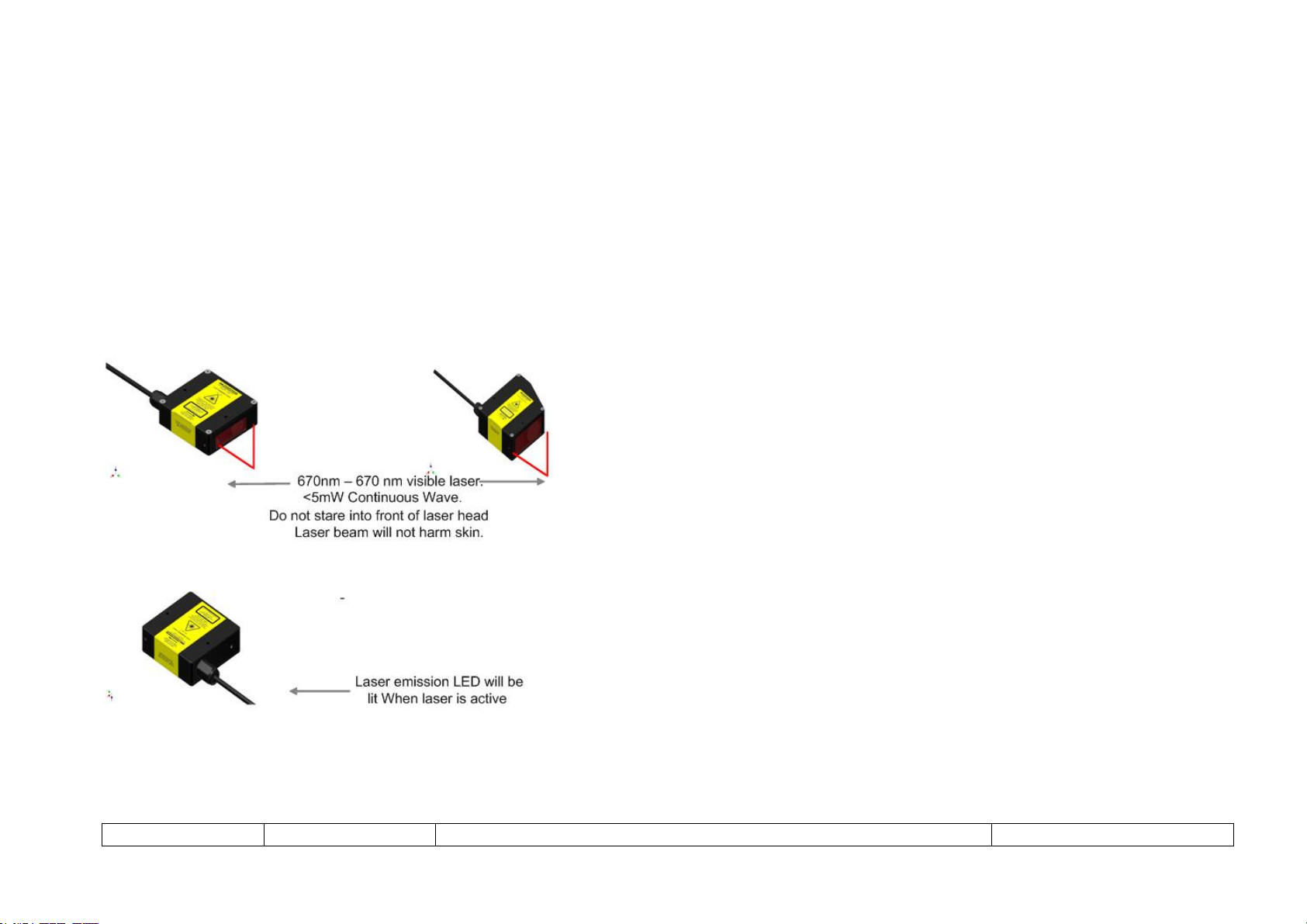
2.3HAZARD AREAS..............................................................................................................................................................................8
3OPERATING PRINCIPLES.....................................................................................................................................................................9
3.1SYSTEM DESCRIPTION..................................................................................................................................................................9
3.2INSTALLATION AND SET UP..........................................................................................................................................................9
3.2.1Environments that are known to cause problems.......................................................................................................................9
3.2.2Head Orientation ......................................................................................................................................................................10
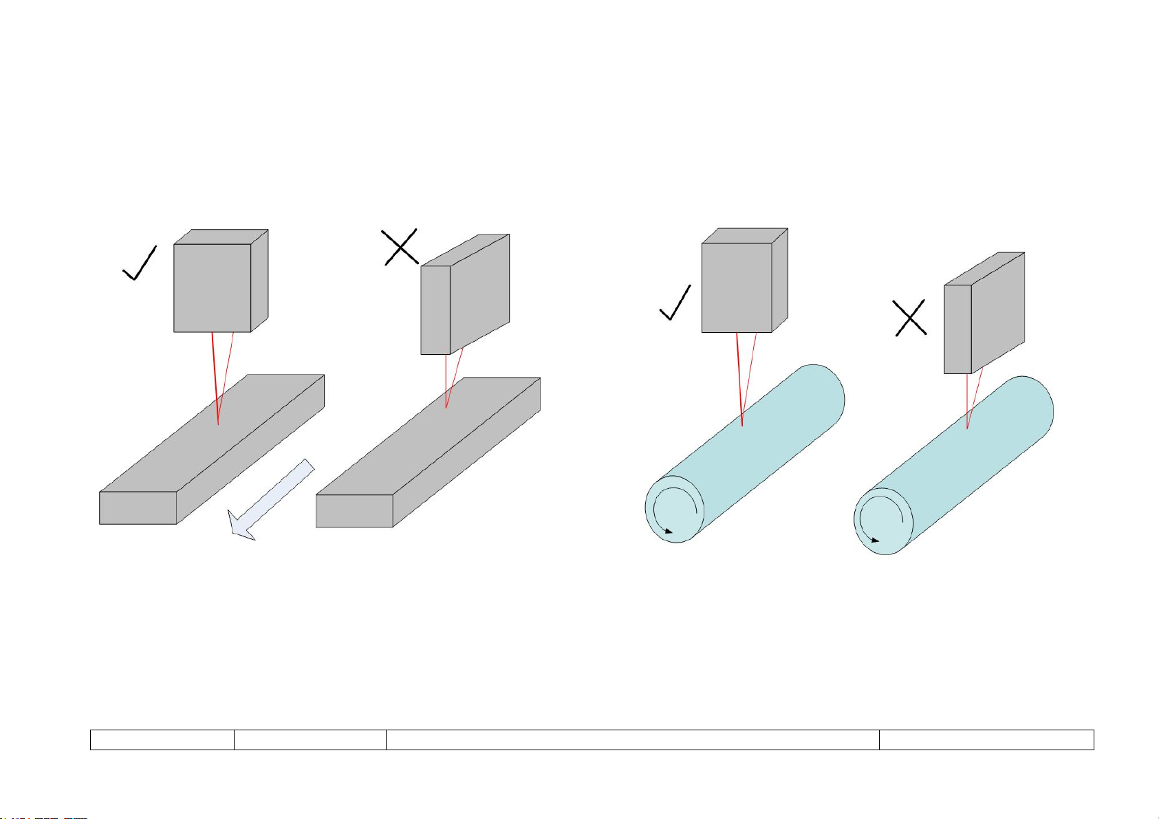
3.2.2.1Moving Targets ..................................................................................................................................................................10
3.2.2.2Slots and Walls ..................................................................................................................................................................11
3.2.3Mounting...................................................................................................................................................................................12
3.3 LED INDICATOR, DIFFUSE AND SPECULAR MODE .....................................................................................................................13
4KEY FEATURES...................................................................................................................................................................................14
4.1.1Laser Head Filter......................................................................................................................................................................14
4.1.2Level Cut Time .........................................................................................................................................................................14
4.1.3Laser Beam Control..................................................................................................................................................................15
5Orbit and ORBIT ACS INTERFACES ...................................................................................................................................................15

Page 3 of 15 503158 ISSUE 3 EDCR21694
FDA NOTICE
This product complies with FDA CFR Title 21 Parts 1040.10 and 1040.11 excepting for variations relevant to FDA Laser Notice No. 50 (June 24, 2007).
IEC NOTICE
This product complies with IEC 60825-1:2007.

Page 4 of 15 503158 ISSUE 3 EDCR21694
1 INTRODUCTION
Solartron Metrology’s Class 3 visible laser gauge sensor combined with Solartron’s Orbit and Orbit ACS products offers a solid non
contact metrology solution for many applications
There are two versions of the laser the LTH Laser which is the highest performing laser in the range and the LTM laser which has lower
resolution. In this manual where information is common to both laser products the term LTX is used to mean either LTH or LTM

Page 5 of 15 503158 ISSUE 3 EDCR21694
2 SAFETY, WARNINGS AND CAUTIONS
2.1 WARNINGS AND CAUTIONS
Symbol Definitions and Explanation
Electrical Shock/Electrocution Hazard.
Laser Aperture.
Class 3R: Is considered safe if handled carefully, with restricted
beam viewin
g
.

Page 6 of 15 503158 ISSUE 3 EDCR21694
SAFETY, WARNINGS AND CAUTIONS (continued)
Beam Paths
The beam emitted by the laser sensor should be terminated at the end of its useful path. Open
laser beams should be located above or below eye level. Take special care on highly reflected
targets as the reflected beam may inadvertently be directed into the eye of the user.
WARNING: DO NOT STARE DIRECTLY INTO THE BEAM
This product emits laser radiation. DO NOT stare directly into the beam with the
naked eye or any form of optical equipment. DO NOT stare at reflections of the
beam.
DO NOT point the laser at a person’s eye.
WARNING: DO NOT USE TO PROTECT THE HUMAN BODY
This device is not intended to be used in applications or systems where it will
directly or indirectly function to protect the human body

Page 7 of 15 503158 ISSUE 3 EDCR21694
SAFETY, WARNINGS AND CAUTIONS (continued)
WARNING: DO NOT USE IN EXPLOSIVE ENVIRONMENTS
Do not use this product in environments containing flammable liquids,
flammable gases, or flammable particulate matter
WARNING: DO OPEN OR MODIFY THE LASER HEAD
Laser radiation levels inside the head can exceed the rated levels outside of the
head. Modification of the laser head may expose users to unsafe laser radiation
levels beyond the rated levels of the head. There are no user serviceable parts
inside the laser head.

Page 8 of 15 503158 ISSUE 3 EDCR21694
2.2 SAFETY FEATURES
Aperture Cover-For Class 3B laser (inclusive) and higher class laser heads, an aperture cover will be supplied. This cover will block the laser light from exiting the
laser head. For Class 3R (inclusive) and lower class laser heads, an aperture cover will not be provided.
Laser ON LED-This product has a range indicator LED which also functions as a Laser ON indicator. When the range LED indicator is on (any color), the laser diode
is activated.
2.3 HAZARD AREAS
Although the lasers are not considered hazardous during normal operation, do not stare directly into the laser beam.
Due to the hazard potential associated with a class 3R and 3B lasers, only persons who have received appropriate training should be placed in control of this
equipment.

Page 9 of 15 503158 ISSUE 3 EDCR21694
3 OPERATING PRINCIPLES
3.1 SYSTEM DESCRIPTION
The Solartron LTX laser system uses the principle of laser triangulation to perform a one dimensional measurement of a target. This can
be used to measure height, profile, distance, displacement, thickness, alignment etc. (For some measurement applications more than one
laser may be required).
The LTX laser projects a beam of light onto a surface which is then reflected back, a CMOS array detects the position of the returned
beam this is then converted into a distance measurement. Auto Gain is used to adjust the laser power to be optimum for the surface being
measured. The laser is suitable for measuring on all types of diffuse surfaces such as black, colored, metallic, wood, ceramic, steel or
plastics.
As an Orbit® product the LTX is compatible with all other Solartron Metrology Orbit products and can be used to form complex
measurement systems combining both contact and non contact measurements.
3.2 INSTALLATION AND SET UP
The LTX operates by emitting a coherent light source and monitoring the reflected response. Using this product in environments that
impairs optical operations will adversely affect the performance.
3.2.1 Environments that are known to cause problems
Conditions where condensation is known to occur on the exterior surfaces of the LTX
Conditions where water is directly sprayed onto the LTX.
High dust or small particulate environments
Environments where chemicals, especially organic solvents can damage seals and glass surfaces.
Environments where gaseous chemicals, can penetrate seals and damage components inside the LTX.
Mounting in an environment where the LTX is subject to shock or vibration.
Mounting in areas that have a high ambient light (especially in the range 630 nm to 800 nm) (red to near infrared).

Page 10 of 15 503158 ISSUE 3 EDCR21694
3.2.2 Head Orientation
3.2.2.1 Moving Targets
The orientation of LTX relative to a moving target can affect the performance, as a general rule position the wide face of the LTX
perpendicular to the motion.

Page 11 of 15 503158 ISSUE 3 EDCR21694
3.2.2.2 Slots and Walls
When measuring near a wall or measuring in a slot ensure that the reflected beam is not blocked or reflected away from the head by any
obstruction.

Page 12 of 15 503158 ISSUE 3 EDCR21694
3.2.3 Mounting
The LTX has two mounting holes for a M3.5 screw or #6 ANSI/ASME screw. Do not exceed a tightening force of 2.3 Nm (20 in Lbs). A
suitable thread locking agent is advised.
The LTX has three reference surfaces which may be used to align the head for optimal performance. The primary surface A is formed by
the raised mounts on bottom of the head. The second B is the front of the head and the third closest to the emitter.
When mounting the head the goal is to have the Reference Surface B parallel as possible to the plane of the target. Take care when using
mechanical blocks etc to set up the laser as the window may be scratched.
Measurement Set Up

Page 13 of 15 503158 ISSUE 3 EDCR21694
3.3 LED INDICATOR, DIFFUSE AND SPECULAR MODE
The green led indicates the most accurate position for measurement.

Page 14 of 15 503158 ISSUE 3 EDCR21694
4 KEY FEATURES
4.1.1 Laser Head Filter
The laser filter can be set to improve signal stability via the Orbit Network.
Available Settings: 20 kHz, 4 kHz, 1 kHz, 200 Hz, 25 Hz, 1 Hz and 0.1 Hz
Note that on certain targets, particularly dark targets, setting the filter to 4 kHz or lower may improve performance as the CMOS
integration time is increased at settings of 4 kHz or lower.
When a filter other than 20 kHz is chosen, the effective sampling rate of the head will be reduced from 40 kHz to 20 kHz. This will permit a
longer integration time on the CMOS sensor, which can be useful on absorbing (dark) targets.
Important: Factory Default = 4 kHz.
4.1.2 Level Cut Time
Level Cut Time is used to modify the operation of the Laser head when the received laser intensity is below the dark cut value (~10%) or
above the bright cut value (~75%).
When level cut time is defined, instead of outputting the maximum / minimum displacement value (125% of head range), the Laser head
will continue to output the value measured before the intensity went out of range.
After the cut time expires, the maximum / minimum displacement value will be output.
This function is generally used to handle situations when the target has known features that would cause the head to move to a saturated
value.
An example of this is a plastic plate that has holes drilled in it. When the laser beam moves into the holes, the value will go out of range.
Using the cut time feature, the value before the laser went into the hole will be held.
The unit is 0.1 msec. The minimum value is 0 msec. The maximum cut time is 1000.0 msec.
Factory Default = No cut time.

Page 15 of 15 503158 ISSUE 3 EDCR21694
4.1.3 Laser Beam Control
The laser Beam can be switched off. Allowing the lasers to measure points that are close together where beam interference may cause a
problem. In the beam off mode the laser head remains powered which keeps the laser operating at full performance so that readings can
be taken quickly after turning the beam back on.
5 ORBIT AND ORBIT ACS INTERFACES
The LTX comes connected to either an Orbit module or an Orbit ACS module.
All of the laser functions can be set either using the Orbit Interface controllers such as the USB Interface Module and the Orbit Support
Pack for Windows. Orbit commands to set up the laser can be found in the Orbit Software Manual available on the Solartron Metrology
Web Site.
Instructions for using the Orbit ACS version can be found in the Orbit ACS manual available on the Solartron Metrology Web Site. The
Laser can be set up using either the Orbit ACS Menu commands or via the Modbus Interface
This manual suits for next models
1
Table of contents
Other Ametek Accessories manuals