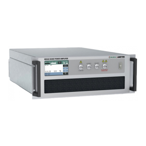
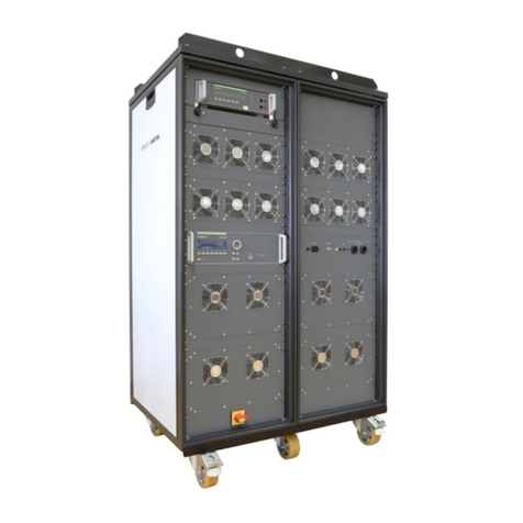
Ametek Teseq TWT Series User manual

Version:
1.0 31.3.2021
Replaces:
Filename:
Quick Start and Saftey TWT Amplifier Series_1.1.docx
Print date:
4.29.202121
QUICK-START GUIDE
AND SAFETY INSTRUCTIONS
TWT Amplifiers:
Teseq TWT Series

Instruction Manual V 1.0 3 / 10
Table of Contents
Table of Contents...............................................................................................................................3
1. Safety ......................................................................................................................................4
1.1 Safety Aspects ............................................................................................................................................4
1.2. Safety symbols and terms ..........................................................................................................................4
1.3 Safety Precaution........................................................................................................................................4
2. Installation ..............................................................................................................................7
2.1 General .......................................................................................................................................................7
2.2 Connecting the line cord. ............................................................................................................................7
2.3 Connecting the chassis to a suitable ground connection. ..........................................................................7
2.4 Connecting the RF cables ..........................................................................................................................7
2.5 Connecting the Safety interlock ..................................................................................................................8
2.6 Connecting an RF Load and Signal Generator ..........................................................................................8
2.7 Line supply input connector ........................................................................................................................ 8
3. Quick Start ..............................................................................................................................9
3.1 Rear Panel Connections .............................................................................................................................9
3.2 Front Panel Connection & Control ..............................................................................................................9
3.3 RF on / RF Standby Operation ...................................................................................................................9
3.4 Amplifier Power On .....................................................................................................................................9
3.5 Applying an RF Signal ................................................................................................................................9
3.6 Switching RF On / Standby.........................................................................................................................9
4MAINTENANCE .....................................................................................................................10
4.1 General cleaning.......................................................................................................................................10
4.2 RF connectors...........................................................................................................................................10
4.3 Air-filter cleaning. ......................................................................................................................................10
4.4 Repairs......................................................................................................................................................10
4.5 Disposal ....................................................................................................................................................10

AMETEK CTS TWT Amplifiers
Quick Start and Safety Guide V 1.0 4 / 10
1. Safety
1.1 Safety Aspects
The amplifier described in this manual is designed to be used only by qualified personnel. Installation and use of
the amplifier in a manner not specified in this manual may impair the protection provided by the amplifier. Before
use, inspect the amplifier for damage which may impair safety.
There are no user-serviceable parts inside the amplifier, and any warranty is rendered void if the seals on any
covers are broken.
The following safety information is intended to protect all installers and operators, and to prevent damage to the
amplifier. It should be read and understood before installing and operating the amplifier.
1.2. Safety symbols and terms
This symbol warns of a potential risk of shock hazard. The symbol on an instrument
shows that that it can source 1000 volt or more, including the combined effect of normal
and common mode voltages. Use standard safety precautions to avoid personal contact
with these voltages.
This symbol indicates where a caution is required. Refer to the operating instructions lo-
cated in the manual to protect against personal injury or damage the equipment.
When used on the amplifier, warns the user of a non-ionising radiation hazard. When
used in this operation manual, alerts the user to the part of the manual that deals with a
non-ionising radiation hazard.
GROUND protective ground terminal
Warns personnel to observe correct lifting practices.
CAUTION:
CAUTION:indicates a potential hazard. It calls attention to a procedure, practice, or con-
dition which, if not followed, could possibly cause damage to equipment. Such damage
may invalidate the warranty. If a “CAUTION” is indicated, do not proceed until its condi-
tions are fully understood and met.
WARNING:
WARNING:indicates a potential hazard. It calls attention to a procedure, practice, or con-
dition which, if not followed, could possibly cause bodily injured or death. If a “WARNING”
is indicated, do not proceed until its conditions are fully understood and met.
1.3 Safety Precautions
Observe all the following precautions to ensure personal safety and prevent damage to the amplifier or equip-
ment connected to it.

AMETEK CTS TWT Amplifiers
Quick Start and Safety Guide V 1.0 5 / 10
WARNING: Do not touch the inner conductor of the RF-output connector.
High voltages can occur on the inner conductor of the RF output connector, or on cables or anten-
nas connected to it. These can cause RF burns if touched.
WARNING:The Amplifier is required to be connected to a suitable ground point.
The amplifier conforms with IEC Safety class 1, meaning that it is provided with a protective ground-
ing terminal. This is through the line supply cord to the centre pin of the power inlet connector. To
maintain this protection, the line supply cord must always be connected to the source of line supply
via a socket with a grounded contact. Do this before making connections to the RF-input or RF-
output connectors of the amplifier.
Without the protective ground connection, all parts of the amplifier constitute a potential shock hazard.
WARNING: Use the correct power cord.
Use only the line supply cord and connector specified for the amplifier. Use only a line supply cord
that is in good condition.
WARNING: Do not remove covers or panels.
To avoid personal injury, do not operate the amplifier without the panels or covers in place. Remov-
al of panels will expose the operator to high voltages that can remain in the amplifier after being
switched off for some time.
WARNING: Do not operate in explosive atmospheres.
The amplifier provides no explosive protection from static discharges or arcing components. Do not
operate the amplifier in an atmosphere of explosive gasses.
CAUTION: Avoid static discharges.
The RF input and output connections are static-sensitive and should not be subjected to static dis-
charge.
CAUTION: Do not obstruct the circuit breaker.
Ensure that there are no obstructions that impair the operation of the rear panel line-supply circuit
breaker(s).
CAUTION: Do not obstruct the airflow through the amplifier.
The cooling airflow is drawn in through the front and exhausted at the rear. If this airflow is ob-
structed, overheating of the amplifier may occur.
CAUTION: Do not operate the amplifier outside its specification.
This may cause the amplifier to malfunction or be damaged.
WARNING: Do not touch the exterior of the amplifier (rack mount version) when in use.
The top and side panels of the amplifier can get hot during use, especially on high power models.
CAUTION: Periodically replace the air-intake filters.
Operating the amplifier with the air filters dirty may cause the amplifier to overheat.
CAUTION: Exercise caution when lifting.
The appropriate lifting practices should be observed during transportation, installation, or removal of the amplifi-
er from its mounting position.

AMETEK CTS TWT Amplifiers
Quick Start and Safety Guide V 1.0 6 / 10
WARNING:Use the safety interlock facility within danger areas.
Any area where personnel may come into direct contact with high power RF, or be exposed to non-ionising ra-
diation, should be designated as a danger area. A barrier should be established around any such area, with a
switch in place when the barrier is broken. This switch can be linked to the safety interlock BNC connector on
the rear of the amplifier, thus disabling the amplifier when the barrier is breached.
It is the responsibility of the operator to ensure that the working environment is safe. The ‘safety interlock’ fea-
ture is provided to assist the purchaser in establishing such a ‘safe’ area.

AMETEK CTS TWT Amplifiers
Quick Start and Safety Guide V 1.0 7 / 10
2. Installation
2.1 General
CAUTION!Exercise care when lifting.
Amplifier models that are very heavy have a caution label on the top cover. Appropriate lifting practices should
be observed during transportation, installation, or removal of the amplifier from its mounting position. When
mounted in a rack, the amplifier must not be supported by the front panel fixing holes alone. For easier instal-
lation and removal, we recommend that the amplifier is positioned with its top no more than 1.4 metres above
ground level.
CAUTION: Do not support the whole weight of the amplifier with the front panel handles.
These should only be used for sliding the amplifier in and out on the rack.
♦Note: The amplifier may be lifted using the rear protection handles.
The amplifier is designed to be mounted in a 19” fixed rack installation. When mounted in a rack, use a support
tray-slider-assembly or rack sliders, especially for heavy amplifier models.
CAUTION:Do not obstruct the airflow through the amplifier.
At least 200mm clearance should be allowed behind the amplifier, so that air flow and connecting cables are not
obstructed. An unobstructed area of at least 200mm should be allowed in front of the amplifier front panel air-
intakes.
CAUTION: Even though the ambient air temperature may be within the amplifier’s specification, the
internal temperature may rise above operational limits if it is operated in direct sunlight.
The cooling airflow is drawn in through the front and exhausted at the rear. If this airflow is obstructed, overheat-
ing of the amplifier may occur. For correct amplifier operation, airflow through the unit must be maintained.
2.2 Connecting the line cord.
CAUTION:It is essential that the amplifier operates from a line source that does not apply voltages
and frequencies between the line conductors (or between either line conductor and ground) that are
outside the range detailed in the specification sheet.
CAUTION:Ensure that the line cord does not interfere with the operation of the rear panel line-input
circuit breaker(s).
2.3 Connecting the chassis to a suitable ground connection.
To improve EMC immunity, bond the amplifier to a good ground with a conductor of 4 sq.mm or the
equivalent earth braid, a ground post being provided for this purpose on the rear panel. Although it
provides an extra measure of safety, this is NOT a protective earth connection. The protective earth
is the ground pin on the line supply connector(s).
2.4 Connecting the RF cables
CAUTION: Ensure that the RF source is in, “RF OFF” mode when making connections.
CAUTION: Ensure any cables and connectors mating with the RF input and RF output connectors
are of 50-ohm impedance and are designed to handle the power at the frequencies generated by
the amplifier. Although very similar, 75-ohm connectors must not be used.
AMETEK CTS TWT Amplifiers
Quick Start and Safety Guide V 1.0 8 / 10
Use cable with the lowest loss that is practical. The connectors or wave guide should not be over-tightened, and
any tightening instructions for the connector or wave guide should be observed. Ensure that any bends in ca-
bles conform to the recommended minimum-bend-radius of those cables, especially where the cables enter the
RF connectors.
2.5 Connecting the Safety interlock
WARNING:Use the safety interlock facility within danger areas.
If the amplifier is to be connected to an antenna, personnel may be exposed to non-ionising radiation. In such
systems, the safety interlock function should used.
Connection (via the rear panel) is with a BNC-type connector. We recommend that shielded cable is used for all
interlock connections to ensure EMC immunity.
The current in the safety-interlock circuit is less than 1mA, so cable with a low current capacity is suitable.
If you do not need this function, fit the supplied BNC shorting-link in place. Failure to do this will result in the
amplifier latching in an “Interlock Open” status which switches the amplifier into standby mode.
2.6 Connecting an RF Load and Signal Generator
CAUTION: Ensure the RF output of the amplifier is connected to a suitable load that is rated for the
frequency and peak RF output of the amplifier.
Do not switch the amplifier on without the RF output connected to a suitable 50ohm load. Switching the amplifier
to an “RF on” state without a suitable load connected has the potential to damage the amplifier. The load must
be rated for the frequency and maximum power the amplifier can generate. Any under rating in the load can
lead to it being damaged with excessive power from the amplifier.
The selection of the load is the responsibility of the customer. The load can vary in type though it is important to
note if the load is a poor match this will affect the amplifiers ability to deliver full power.
2.7 Line supply input connector
Dependent on RF output power requirements the amplifier power supply is equipped with an IEC or a high cur-
rent 3 phase / 5 wire Star configuration (184-264 VAC line to neutral) or 4 wire Delta configuration (184-264
VAC line to line) connector for high power models. The amplifier systems are supplied with mating power cords.
No wiring of power supply leads is required from the customer. Always ensure the supplied power supply lead is
fully inserted and locked into place before the amplifier is powered On.
120/240 single Phase
IEC C20 Mains Inlet
Three Phase
L2120-C Mains Inlet
Three Phase
IEC 60309 Mains Inlet

AMETEK CTS TWT Amplifiers
Quick Start and Safety Guide V 1.0 9 / 10
3. Quick Start
3.1 Rear Panel Connections
A. Remote interface panel
B. Mians power connector
C. Earth/Ground Terminal
D. Interlock
3.2 Front Panel Connection & Control
A. LCD Display
B. AC Mains on indicator
C. Standby (push button)
D. Operate (push button)
E. Air inlet cover and filter
F. FWD RF sample port
RFL RF sample port
G. RF output (coaxial or waveguide)
H. Modulator Input (BNC
I. Main’s switch
J. RF Input
3.3 RF on / RF Standby Operation
CAUTION:Ensure mains voltage is present at the mains power connector.
3.4 Amplifier Power On
When the equipment is first switched on, especially if it has been in storage for a period time the initial operation
will need to be performed at low power. In addition, for pulsed units it’s recommended to start the unit with a
short (1 µs) pulse and slowly widen back to the desired operating pulse width, this will help to remove any gas
that may have built up in the TWT. To avoid TWT Arcs and damage caused by excessive gas build-up, it is ad-
visable to run the Amplifier for at least 24 hours every 6 months.
•Connect power cord to a suitable power source. (B)
•Engage the front panel circuit breaker. (I)
•Display screen becomes illuminated. (A)
•Amplifier is on in a “Standby” State. (C)
3.5 Applying an RF Signal
•Set to “RF OFF” connect a suitable signal generator to the RF input (J)
•To start we recommend the power level is set to -25dBm.
•For pulse TWT a 1µS pulse width.
•Switch RF signal generator to “RF on”
3.6 Switching RF On / Standby
•Pressing the “operate” button (D) on the front panel will switch the amplifier to an “RF On” state.
•The power from the signal generator can now be turned up until the required output power from the am-
plifier is achieved.
•Pressing the “standby” button will return the amplifier to the standby state.

AMETEK CTS TWT Amplifiers
Quick Start and Safety Guide V 1.0 10 / 10
4 MAINTENANCE
4.1 General cleaning
For cleaning the front panel, use an anti-static foam cleaner and a soft lint-free cloth or tissue. Using abrasive
materials or strong solvents may damage the surface finish or the front panel overlay.
4.2 RF connectors
If the RF connectors or wave guide are used frequently, or left disconnected for long periods, there is a tenden-
cy for dirt and oxide deposits to build up. This increases the contact resistance and creates localized heating of
the “RF out” connector pin, which may cause damage on high power models. Periodically inspect the inner pins
of the RF connectors for damage or deposits, and carefully clean if required.
CAUTION:Do not use cleaning materials that leave a residue or that are abrasive for cleaning the
RF connectors, as this seriously degrades their performance.
When storing the amplifier for long periods, the RF connectors should be protected with the plastic covers pro-
vided.
4.3 Air-filter cleaning.
CAUTION:Operating the amplifier with the air-filter clogged, may cause the amplifier to overheat.
The air-intake-filter on the amplifier front panel should periodically be checked for cleanliness. If it is seen to be
obstructed with any dust or debris this should be cleaned away before the amplifier is operated.
4.4 Repairs
Repair work is to be carried out exclusively by an authorized AMETEK CTS repair department.
WARNING: Voltages of more than 230 VAC and are generated within the instrument. Do not open
the cover.
Only original replacement parts and accessories are to be used.
Do not continue to use the instrument in the event of mechanical damage occurring. The metal chassis also
performs insulating and protective functions.
4.5 Disposal
For the disposal of electronic devices, the country-specific regulations are to be considered. The
equipment should be delivered to a specialized waste collection center.
Milmega and Teseq’ devices can be returned to AMETEK CTS in England
or to their agency for
adequate disposal. Alternatively, the equipment can be handed over to a specialized enterprise
for disposal of electronic devices.
Details to used material and components.
The traveling wave tubes in these products contain Beryllium Oxide, and other components contain PTFE. The
appropriate precautions and regulations must be observed concerning the disposal of this amplifier and certain
internal components. Do not crush or incinerate.
Table of contents
Other Ametek Amplifier manuals

Ametek
Ametek Milmega AS Series User manual

Ametek
Ametek VDS 200Q Series Instruction Manual

Ametek
Ametek 7124 User manual

Ametek
Ametek Signal Recovery 5402 User manual

Ametek
Ametek SW 5550AE User manual

Ametek
Ametek SmartWave SW5550A User manual

Ametek
Ametek 5113 User manual

Ametek
Ametek 7230 User manual

Ametek
Ametek 7270 User manual

Ametek
Ametek Teseo CBA Series User manual
Popular Amplifier manuals by other brands

VIETA
VIETA HAM75 owner's manual

Harman Kardon
Harman Kardon SIGNATURE 2.1 owner's manual

Traynor
Traynor Bassmaster YBA200 Service manual

Traynor
Traynor AM150T - Service manual

Cable Electronics
Cable Electronics CE Labs HDMI Distribution Amplifier HA 8 instruction manual

Pearller
Pearller HY1060MBT instruction manual