Ametek TESEO CDN HSS-2 User manual

COUPLING DECOUPLING NETWORK FOR
UNSHIELDED SYMMETRICAL HIGH SPEED
COMMUNICATION LINES
CDN HSS-2
USER MANUAL

COUPLING DECOUPLING NETWORK FOR
UNSHIELDED SYMMETRICAL HIGH SPEED
COMMUNICATION LINES
CDN HSS-2
USER MANUAL

3
85-243826 E03
CONTENT
1. Safety advice ........................................................................................................................4
1.1. General......................................................................................................................................................4
1.2. Applicable safety standards.....................................................................................................................4
1.3. Safety symbols used on the product.......................................................................................................4
1.4. Installation.................................................................................................................................................4
1.5. Test execution ..........................................................................................................................................5
2. Unpacking, storage and transport.......................................................................................6
2.1. General......................................................................................................................................................6
2.2. Storage and transport ..............................................................................................................................6
2.3. Unpacking.................................................................................................................................................6
2.4. Scope of delivery......................................................................................................................................6
3. Description of the product................................................................................................... 7
3.1. General......................................................................................................................................................7
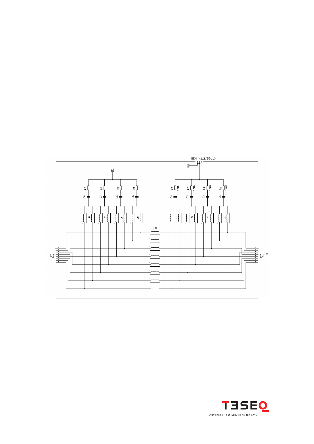
3.2. Functional schematic...............................................................................................................................7
3.3. Construction of the product.....................................................................................................................8
4. Application............................................................................................................................9
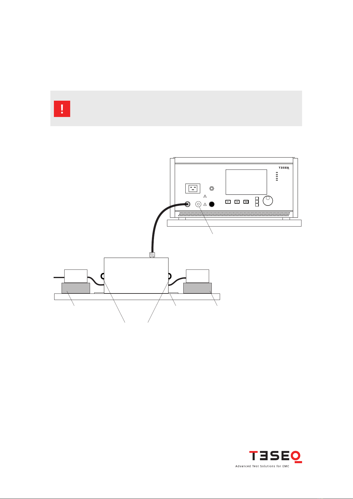
4.1. Setup.........................................................................................................................................................9
4.2. Coupling path to the pair under test (Jumper settings)........................................................................10
4.3. Power over Ethernet (PoE).....................................................................................................................12
4.4. One pair (two lines) application with DC and LF...................................................................................12
5. Verication..........................................................................................................................12
5.1. Voltage....................................................................................................................................................12
5.2. Current....................................................................................................................................................13
6. Technicalspecication .......................................................................................................14
7HFKQLFDOVSHFLFDWLRQVRI&’1+66..................................................................................................14
0HFKDQLFDOVSHFLFDWLRQVRI&’1+66 ..............................................................................................14
7. Maintenance.......................................................................................................................15
7.1. General....................................................................................................................................................15
7.2. Cleaning..................................................................................................................................................15
8. Disposal...............................................................................................................................15

1.4. Installation
&RQQHFW WKH &’1 ZLWK WKH JURXQG SODQH EHIRUH XVLQJ 7KH RSHUDWLRQ ZLWKRXW SURSHU HDUWK FRQQHFWLRQ LV
prohibited.Operatethe equipmentonly in dry surroundings.Allowany condensation thatoccurstoevaporate
before putting the instrument into operation. Do not exceed the permissible ambient temperature, humidity
or altitude.
&RQQHFWLRQVDUHQRWSURWHFWHGE\IXVHVLQVLGHWKH&’1$YRLGDQ\RYHUORDGZLWKDGHTXDWHDUUDQJHPHQWV
4
CDN HSS-2
7KHFRXSOLQJDQGGHFRXSOLQJQHWZRUNV&’1FDQZRUNDWGDQJHURXVYROWDJHV
These operating instructions form an integral part of the equipment and must be available to the operating
SHUVRQQHODWDOOWLPHV$OOWKHVDIHW\LQVWUXFWLRQVDQGDGYLFHQRWHVDUHWREHREVHUYHG1HLWKHU7HVHT*PE+
nor any of the subsidiary sales organizations or the manufacturer can accept any responsibility for personal,
material or consequential injury, loss or damage that results from improper use of the equipment and acces
sories.
1. SAFETY ADVICE
1.1. General
■8VHRIWKH&’1LVUHVWULFWHGWRDXWKRUL]HGDQGWUDLQHGVSHFLDOLVWV
■In the fault case dangerously high voltage may be on the housing.
■The coupling network housing must be properly grounded (earthed).
■Operate the equipment only in dry surroundings.
■This instrument is not designed for use in an explosive atmosphere.
■Only approved accessory items, connectors, adapters, etc. are to be used to ensure safe operation.
■The setup must offer insulation protection against voltage which is at least equal to the pulse voltage.
■The pulse voltage must not be able to find its way to ungrounded metallic objects even if the EUT is faulty
or fails.
■Depending on the type of EUT and especially on its cabling, a considerable amount of interference can
be radiated which could affect nearby systems and radio communication. These environmental interfer
ence effects to be controlled by the user through the use of suitable measures such as a Faraday cage,
shielded cable runs, etc.
1.2. Applicable safety standards
Development and manufacture of the instrument complies with ISO 9001. The product conforms with the
UHTXLUHPHQWVRIWKH/RZ9ROWDJH’LUHFWLYH/9’(&EDVHGRQ’,1(1
1.3. Safety symbols used on the product
WARNING: Improper or careless handling can be fatal!
Use of the CDN is restricted to authorized and trained specialists
Protective earth (earth terminal)Attention: Refer to manual

1.5. Test execution
The test area must be organized so that no unauthorized persons have access during execution of a test. If
a safety contact (interlock) is used as a means of access control to the test area (e.g. Faraday cage), then an
additional contact in series with any hazardous voltages or currents is necessary to provide protection
for parts of the EUT that are in danger of being touched.
EUTs, together with their accessories and cables, are to be considered live during a test. The test generator
must be stopped and the EUT supply interruptedbefore any work can be performed onthe EUT. This can often
be achieved by opening the interlock circuit, depending on the type of generator in use.
The EUT is to be tested only in a protective cage or under a hood which provides protection against electric
shock and all manner of other dangers pertaining to the particular EUT.
The safety instructions for all instruments and associated equipment in the test setup are to be observed.
7KHFRQJXUDWLRQRIWKHWHVWVHWXSLVWREHVWULFWO\LQFRPSOLDQFHZLWKWKHPHWKRGVGHVFULEHGLQWKHUHOHYDQW
standard to ensure that the test is executed in a compliant manner.
5
85-243826 E03

6
CDN HSS-2
2. UNPACKING, STORAGE AND TRANSPORT
2.1. General
Save allpacking materials!They willbeneeded inorder tosafely packagethe equipment for calibration service
or repair.
Packaging materials
■&DUWRQ &DUGERDUG
■3DGGLQJ &)&IUHHSRO\VW\UHQHIRDP
■3ODVWLFEDJV 3RO\HWK\OHQH
■Avoid the risk of condensation!
If a large temperature difference has occurred, allow time for the temperature to stabilize. This may take
several hours.
2.2.Storage and transport
■Do not stack, either packaged or unpacked.
■Do not stand on end; arrows on the packaging must always point upwards.
■Protect from dampness, heat, cold and rain.
■Do not throw.
■Do not sit or stand on the instrument and packaging.
2.3. Unpacking
■Is the packaging damaged? If YES ☎transportation company
■$UHDOOWKHSDFNDJHVSUHVHQWDQGFRUUHFW" ,I12
☎transportation company
■Open the packaging, remove the accessories.
■Grip the instrument at the sides and lift it from the packaging.
■Are the instrument or accessories damaged? If YES ☎transportation company
■$UHWKHFRQWHQWVRIWKHSDFNDJHFRPSOHWH" ,I12
☎Teseq sales office
■Keep the instruction manual with the instrument.
■Keep the packaging.
2.4. Scope of delivery
■&’1+66
■8 Jumper (4 mm safety banana)
■Operating manual

7
85-243826 E03
3. DESCRIPTION OF THE PRODUCT
3.1. General
KH&RXSOLQJ’HFRXSOLQJ1HWZRUN&’1 +66 LVGHVLJQHGIRUFRQYHQLHQWVXUJHWHVWLQJZLWK MVSXOVHV
DVGHQHGLQ,(&(1 RQXQVKLHOGHGV\PPHWULFDOKLJKVSHHGWHOHFRPPXQLFDWLRQOLQHVHJ (WKHUQHW
&RXSOLQJPRGHVWR RU SDLUVDUHJLYHQDQGFRXSOHGZLWK L LQVHULHVZLWKDFDSDFLWLYHFRXSOLQJHOHPHQW
7KH&’1 +66 DOORZVWHVWLQJRQ,6’1 DQG(WKHUQHWZLWK%DVH7 DQG%DVH7 DVZHOO3RZHURYHU
Ethernet (PoE) is applicable.
With a surge test voltage of 2 kV is the maximal residual voltage at the AE port only 65 V due to the excellent
decoupling network. Additional decoupling elements are not required to protect the auxiliary equipment
(AE). The high decoupling provides an AE independent pulse shape for the EUT testing. A high measurement
UHSURGXFLELOLW\LVJLYHQE\ XVLQJWKH&’1 +66 7KHGHFRXSOLQJQHWZRUNLVLQDFFRUGDQFHZLWK,(&
Edition 3.
,WFDQEHXVHGZLWK7HVHTRV16* VHULHVRUDQ\LQGXVWU\VWDQGDUGVXUJHJHQHUDWRUZLWKWKHDSSURSULDWHFRQ
nector adapter.
3.2. Functional schematic
Figure 1: Functional schematic of the CDN HSS-2

8
CDN HSS-2
3.3. Construction of the product
Figure 2: CDN HSS-2
Figure 3: CDN HSS-2, view to the EUT port
Figure 4: CDN HSS-2, view to the AE port
EUT port
Jumper for selecting the coupling path to the pair under test (not shown for the AE port)
Jumper for selecting the coupling path to the pair
Handle
Handle
EUT port
AE port
AE port (not shown)
Protective earth (PE) bolt
Ground plane of the CDN with notch for additional
adjustment to the ground plane of the set-up
Surge input

9
85-243826 E03
Figure 5: Setup example with CDN HSS-2
4. APPLICATION
4.1. Setup
Each test setup should be carefully planned. All the equipment should be securely positioned, and all cables
should be securely connected.
Caution: The safety advice given in Section 1 and in the generator manual
must be observed. The EUT and the wiring should be handled only
when the generator is not active.
7KHIROORZLQJJXUHSURYLGHVDQH[DPSOHVRIDVHWXS
Auxiliary
equipment
EUT
AE
Equipment
under test
Insulating
(if required)
Ground plane Insulating
AE port EUT port
Surge input
CDN HSS
Short circuit connector
Jumper settings as required for the application
SURGE GENERATOR
EUT Power
Output
Surge
Output
High Low
Power on
Pulse
High voltage active
EUT-Power on
Error
Burst
Output
1
10
100
NSG 3040
7KH(87 QHHGVWREHFRQQHFWHGZLWKDVXLWDEOH873 XQVKLHOGHGWZLVWHGSDLUFDEOHWRWKH5- RQWKH(87VLGH
RIWKH&’1 +66 $Q DX[LOLDU\HTXLSPHQWLVUHTXLUHGWREHFRQQHFWHGWRWKH$(VLGHRIWKH&’1 +66 7KH
SXOVHFRQQHFWLRQVIURPWKHVXUJHJHQHUDWRULVSOXJJHGLQWRWKH+9VRFNHWRIWKH&’1+66
The length and layout of the cables, distances, height above ground plane and other descriptions are given
in the basis and product standards.
The jumper setting for selecting the coupling path to1,2or 4pairs is given in chapter 4.3. Power overEthernet
(PoE) is described in chapter 4.4.

10
CDN HSS-2
Figure 6: RJ45 pin arrangement
4.2.Coupling path to the pair under test (Jumper settings)
7KHFRXSOLQJSDWKWRWKHSDLUXQGHUWHVWZLOOEHVHWE\ XVHRIMXPSHUV,WSURYLGHVWKHFRUUHFW L LQVHULHV
ZLWKDFDSDFLWLYHFRXSOLQJHOHPHQWWRWKHVHOHFWHGOLQHVXQGHUWHVW7KHIROORZLQJWDEOHVDQGJXUHVSURYLGH
examples with more precise details.
Jumper J1 J2 J3 J4 J5 J6 J7 Number of lines
under test
Example given
in gure
3,15- /
XXXX2
X XXX2
X X X X 2 7
X XXX2
,6’1EDVLFUDWHDFFHVV6 X X X X 4 8
,6’1SULPDU\UDWHDFFHVV X X )* )* X 4 9
%DVH7 %DVH7 X X X X 4 10
ATM, FDDI X X X X 4
%DVH7 %DVH7 X X X X 8 11
PIN/RJ45 7-8 3-6 4-5 1-2
Jumper J1 J2 J3 J4
(,$7,$% P4 P3 P1 P2
EIA/TIA 568A P4 P2 P1 P3
Table 1: Relation between RJ45 pin arrange-
ment, jumper settings and EIA/TIA
specifications
)* short 4 mm test lead (safety banana connectors) between outer pins of J5 and J6
Table 2: Jumper settings in relation to EIA/TIA 568B
12345678
123456

11
85-243826 E03
Figure 7: Jumper settings for testing on
pin 4 and 5
Figure 8: Jumper settings for ISDN basic
rate access, S0
Figure 9: Jumper settings for ISDN pri-
mary rate access
Figure 10: Jumper settings for 10BaseT,
100BaseT
Figure 11: Jumper settings for 1000BaseT,
100BaseT4
RJ45 PIN
7 - 8
PIN
3 - 6
PIN
4 - 5
PIN
1 - 2
Jumper 5 Jumper 6
Jumper 3
Jumper 7
RJ45 PIN
7 - 8
PIN
3 - 6
PIN
4 - 5
PIN
1 - 2
Jumper 5 Jumper 6
Jumper 2
Jumper 3
RJ45 PIN
7 - 8
PIN
3 - 6
PIN
4 - 5
PIN
1 - 2
Jumper 7 Short 4 mm test lead
between outer pins
Jumper 4
Jumper 3
RJ45 PIN
7 - 8
PIN
3 - 6
PIN
4 - 5
PIN
1 - 2
Jumper 5 Jumper 6
Jumper 2
Jumper 4
RJ45 PIN
7 - 8
PIN
3 - 6
PIN
4 - 5
PIN
1 - 2
Jumper 1
Jumper 2
Jumper 3
Jumper 4

12
CDN HSS-2
4.3. Power over Ethernet (PoE)
7KH&’1 +66 DOORZVWKHXVHRIWKH3RZHURYHU(WKHUQHW3R( IXQFWLRQ,QFDVHWKHKDQGVKDNHSURFHGXUHIDLOV
DOOMXPSHUVQHHGVWREHUHPRYHGIURPWKH&’1 +66 7KHMXPSHUVQHHGWREHUHSODFHGDIWHUHVWDEOLVKPHQW
of a successful PoE connection for proceeding the surge testing.
4.4.One pair (two lines) application with DC and LF
All applications with coupling toone pair (two lines)only allowed withabsence ofDCand lowfrequency signals
EHORZ .+] 7KHVLJQDOVZLOOEHVKRUWHGE\ WKHLQWHUQDO=FKRNHVRIWKH&’1 +66 7HVHTUHFRPPHQGVWKH
XVRI&’1IRUWKLVDSSOLFDWLRQHYHQMVSXOVHVZLWKXSWRN9FDQEHDSSOLHG
5. VERIFICATION
5.1. Voltage
7KHSXOVHVSHFLFDWLRQFDQEHYHULHGZLWKWKHIROORZLQJVHWXSV7KH$( DQG(87VLGHRIWKH&’1 +66 QHHG
WREHFRQQHFWHGLQWKHFRPPRQ PRGHIRUWKHUHTXHVWHGDSSOLFDWLRQ$Q RVFLOORVFRSHZLWKD 0L LQSXWLV
FRQQHFWHGYLDD GLYLGHUZLWKWKH(87VLGHRIWKH&’1 +66 7KHSXOVHFRQQHFWLRQVIURPWKHVXUJH
JHQHUDWRULVSOXJJHGLQWRWKH+9VRFNHWRIWKH&’1+66
The jumper setting for selecting the coupling path is required in relation to the application.
Common mode adapter
as required for the application
Shorted Ground
plane
Divider
1/1000
1 MΩ input
AE port EUT port
Surge input
CDN HSS
Jumper settings
as required for
the application
Short circuit connector
SURGE GENERATOR
EUT Power
Output
Surge
Output
High Low
Power on
Pulse
High voltage active
EUT-Poweron
Error
Burst
Output
1
10
100
NSG 3040
OSCILLOSCOPE
Channel 1 Channel 2 Channel 3 Channel 4
USB
USB
Power
Tuning
Back 0.
1
4
7 8
5
23
kHz
dBm
6
9MHz
dBµV
Hz
V
Enter
StSizeStSize StSize
Step
1
Step
2
Step
3
DIA
MEAS FOR
DIS
SCL
TRA
STO
FRQ LVL
RCL
MOD
MOD
STO
CH 1 CH 2
RCL
STO
FRQ LVL
RCL
MOD
MOD
Stop
Run Hold
STO
FRQ LVL
RCL
MOD
MOD
Local
2nd
Help
RF
ON/OFF
Figure 12: Example of a setup for verifying the pulse parameters with measuring the open-
circuit voltage

13
85-243826 E03
Common mode adapter
as required for the application
Shorted ShortedGround
plane
Current
probe
50 Ω input
AE port EUT port
Surge input
CDN HSS
Jumper settings
as required for
the application
Short circuit connector
SURGE GENERATOR
EUT Power
Output
Surge
Output
High Low
Power on
Pulse
High voltage active
EUT-Poweron
Error
Burst
Output
1
10
100
NSG 3040
OSCILLOSCOPE
Channel 1 Channel 2 Channel 3 Channel 4
USB
USB
Power
Tuning
Back 0.
1
4
7 8
5
23
kHz
dBm
6
9MHz
dBµV
Hz
V
Enter
StSizeStSize StSize
Step
1
Step
2
Step
3
DIA
MEAS FOR
DIS
SCL
TRA
STO
FRQ LVL
RCL
MOD
MOD
STO
CH 1 CH 2
RCL
STO
FRQ LVL
RCL
MOD
MOD
Stop
Run Hold
STO
FRQ LVL
RCL
MOD
MOD
Local
2nd
Help
RF
ON/OFF
Figure 14: Example of a setup for verifying the pulse parameters with measuring the short-
circuit current
Figure 13: Typical voltage waveform
5.2. Current
7KH$( DQG(87VLGHRIWKH&’1 +66 QHHGWREHFRQQHFWHGLQWKHFRPPRQ PRGHIRUWKHUHTXHVWHGDSSOLFD
WLRQ$Q RVFLOORVFRSHZLWKD L LQSXWLVFRQQHFWHGZLWKDVXLWDEOHFXUUHQWSUREH7KH$( DQG(87VLGHRI
WKH&’1 +66 LVVKRUWHG%HWZHHQWKHFRPPRQ PRGHDGDSWHULQVHUWHGLQWKH(87VLGHRIWKH&’1 +66
and ground is placed the current probe for measuring the short cut. The pulse connections from the surge
JHQHUDWRULVSOXJJHGLQWRWKH+9VRFNHWRIWKH&’1+66
The jumper setting for selecting the coupling path is required in relation to the application.

14
CDN HSS-2
6. TECHNICAL SPECIFICATION
6.1. Technical specifications of CDN HSS-2
&LUFXLWGLDJUDP DFFRUGLQJWR)LJRI,(&(GLWLRQ
0D[VXUJHWHVWYROWDJH N9wVSXOVHDVSHU,(&(1
0D[VXUJHWHVWFXUUHQW $wVSXOVHDVSHU,(&(1
&RXSOLQJPRGH &RPPRQPRGHWRRUSDLUVZLWKUHVSHFWWR
&’1FKDVVLV
&RXSOLQJHOHPHQWV bLQVHULHVZLWKFDSDFLWLYHFRXSOLQJHOHPHQWV
0D[UHVLGXDOWHVWYROWDJHDW$(SRUW 9DWN9VXUJHWHVWYROWDJH
6XUJHLQSXWFRQQHFWRU +9FRQQHFWRUIHPDOH)LVFKHU’$
$SSOLFDWLRQV ,6’1%DVH7%DVH7HWFVZLWFKDEOHSHU
jumper, PoE applicable
&DEOHW\SH ZLUHXQVKLHOGHGWZLVWHGSDLU873
,QVHUWLRQORVVW\SLFDO G%DW0+]
2WKHUW\SLFDOQHWZRUNOLPLWV 7,$$&DWHJRU\76%/LQN
0D[RSHUDWLQJVSHHG %DVH7
0D[RSHUDWLQJYROWDJH 9’&EHWZHHQSDLUV
0D[RSHUDWLQJFXUUHQW $UDWHGIRU3RZHURYHU(WKHUQHW
&RQQHFWLRQ(87SRUW$(SRUW 5-IHPDOH
*) +10 % tolerance allowed
6.2. Mechanical specifications of CDN HSS-2
6L]H:[+[’LQPP [[
:HLJKW DSSUR[NJ
Figure 15: Typical current waveform

15
85-243826 E03
7. MAINTENANCE
7.1. General
7KH&’1V LQFOXGLQJWKHDFFHVVRULHVQHHGQRVSHFLDOPDLQWHQDQFH7KHPDLQWHQDQFHLVOLPLWHGWRWKHFOHDQLQJ
of the contacts. The life time of the connectors is limited because of the contact durability. Teseq can replace
WKHZRUQRXWFRQQHFWRUVDQGRIIHUVDJHQHUDODGMXVWPHQWRI&’1VZLWKDGDSWHUVZKLFKPLJKWEHQHFHVVDU\
1RPRGLFDWLRQVDUHWREHFDUULHGRXWRQ&’1VDQGDFFHVVRULHVE\WKHXVHU
It is recommended to send the units to a Teseq Service Centre once a year for recalibration.
7.2. Cleaning
The cleaning shall be done with dry cloth. If a wed cleaning would become necessary, make sure that no
humidity will enter inside of the unit and clean the instrument housing with a damp cloth using a little mild,
QRQDEUDVLYHKRXVHKROGFOHDQVHULIQHFHVVDU\
Chemicals must not be used for cleaning purposes
8. DISPOSAL
The unit is constructed that it can be dismantled right down to the component level.

16
. .
®
®
®
. .
Table of contents
Other Ametek Network Hardware manuals
Popular Network Hardware manuals by other brands

Fortinet
Fortinet FortiAnalyzer 800G quick start guide

EMC
EMC VNX Series Installation and operation guide

Digiever
Digiever DS-8200-RM Pro Series Quick installation guide

JOHNSON SYSTEMS
JOHNSON SYSTEMS PRESIDOR PRLC-4 instruction manual

NorcoSEA
NorcoSEA KVM-1501COMBO-S user manual

ADC
ADC ProPatch Miniature Series Specification sheet