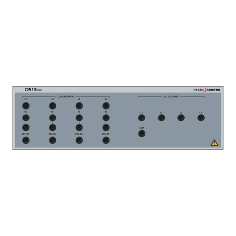
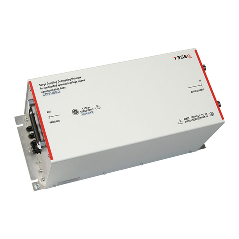
Ametek CDN 117A Series User manual

.
Operating-
manual
CDN 117A - series
CDN 117A-C4-4-1
CDN 117A-C6-4-1
Coupling network for Surge and
Ring wave to signal and datalines
The coupling network of the CDN 117A series are designed for
coupling ringwave, surge- or telecom pulses to signal or data-
lines.
The coupling network expands the range of application of the
impulse generator of the NSG 3040A and NSG 3060A series,
for testing signal and datalines.
Main characteristics are the advantages for handling and the
easy using with banana plugs.
IEC 61000-4-5
IEC 61000-4-12
EN 61000-4-5
EN 61000-4-12
Version:
1.00 / 22.05.2019
The benchmark for emc
Replaces:
No previous version Based on DCD sr
Filename:
UserManual-NSG 117A-Serie-E-V1.00.doc
Printdate:
22.05.19

AMETEK CTS CDN 117A series
Operation Manual V 1.00 2 / 30
AMETEK CTS GmbH
Sternenhofstrasse 15
4153 Reinach BL1
Switzerland
Phone: +41 61 204 41 11
Fax: +41 61 204 41 00
URL: http://www.teseq.com
Copyright © 2019 AMETEK CTS GmbH.
All right reserved.
Information in earlier versions. Specifications subject to change

AMETEK CTS CDN 117A series
Operation Manual V 1.00 3 / 30
Content
1. General.............................................................................................................................4
1.1. Intended use.......................................................................................................................................4
1.2. Safety label on the device ..................................................................................................................4
2. Safety................................................................................................................................5
2.1. Safety aspects....................................................................................................................................5
2.2. Testing and danger.............................................................................................................................6
2.2.1. Coupling networks..............................................................................................................................6
2.2.2. Danger from EUT ...............................................................................................................................6
3. Standards for testing with coupling networks of CDN 117A series............................7
3.1. Description..........................................................................................................................................7
3.2. Coupling- decoupling network models ...............................................................................................8
3.3.Impulse generators.............................................................................................................................8
4. Device functions and operating.....................................................................................9
4.1. Coupling network CDN 117A C4-4-1 and CDN 117A C6-4-1............................................................9
4.1.1. Coupling Surge and Ringwave...........................................................................................................9
4.2. Coupling Line to Line........................................................................................................................10
4.2.1. Coupling with 40 resistor and 0.5 µF capacitor ............................................................................10
4.2.2. Coupling with 40 Ohm and Gas Discharge Tube (GDT)..................................................................10
4.2.3. Coupling with external coupling device ............................................................................................11
4.3. Coupling to GND ..............................................................................................................................12
4.3.1. Test setup Coupling to PE................................................................................................................12
4.4. Test Setup for CDN 117A series application....................................................................................13
5. Technical data CDN 117A series..................................................................................14
5.1. Technical data ..................................................................................................................................14
5.2. Weight and dimension......................................................................................................................14
5.3. AE Protection for auxiliary equipment ..............................................................................................15
6. Maintenance...................................................................................................................18
6.1. General.............................................................................................................................................18
6.2. Calibration and Verification...............................................................................................................18
6.2.1. Factory calibration ............................................................................................................................18
6.2.2. Guideline to determine the calibration period of AMETEK CTS instrumentation.............................18
6.2.3. Calibration of Accessories made by passive components only .......................................................18
6.2.4. Periodically In-house verification......................................................................................................18
6.3. Maintenance, Adjustments, Replacement of Parts ..........................................................................19
6.4. Calibration procedure as per IEC 61000-4-5 Ed3............................................................................20
6.4.1. General.............................................................................................................................................20
6.4.2. Calibration procedure for CDNs for unsymmetrical interconnection lines........................................20
6.4.3. Surge waveform definition................................................................................................................21
6.5. Kalibrationsprozedur gem. IEC 61000-4-12 Ed.3.............................................................................22
6.5.1. Ringwave Impulsformdefinition gem. IEC 6100-4-12 Ed.3 ..............................................................22
7. Delivery Groups.............................................................................................................23
7.1. Delivery groups CDN 117A series coupling network........................................................................23
7.2. Accessories ......................................................................................................................................23
8. Appendix........................................................................................................................24
8.1. Declaration of conformity..................................................................................................................24
8.2. Diagram CDN 117A series...............................................................................................................25
8.3. Typical waves...................................................................................................................................26
8.3.1. Surge coupling..................................................................................................................................26
8.3.2. Ringwave coupling 12 Ω generator impedance ...............................................................................27
8.3.3. Ringwave coupling 30 Ω generator impedance ...............................................................................28
8.3.4. Residual voltage measurements at the AE port...............................................................................29
8.4. Transfer function in function with the EUT Impedance ....................................................................30

AMETEK CTS CDN 117A series
Operation Manual V 1.00 4 / 30
1.
General
1.1.
Intended use
Coupling decoupling networks of the CDN 117A seriesare used for simulating conducted electromagnetic inter-
ference effects for immunity testing to international, national, and manufacturers’standards.
The CDN’s are designed for full compliance conducted electromagnetic compatibility (EMC) test requirements.
The application range is for testing of industrial, light industrial, household or commercial equipment, including
many product family and product standards as per following basic standards.
Only qualified personnel who deal with attendant hazards in impulse generators, can perform installation and
servicing. Before putting in service the attached safety and user manual must be read and applied. The Safety
and user manual are an essential part of the equipment and must be available to the operator always. The user
must obey all safety instructions and warnings.
It is the user’s responsibility to ensure that the test rig does not emit excessive electromagnetic interference
(EMI) that might affect other equipment. The test system itself does not produce any excessive radiation; how-
ever, the injection of interference pulses into the EUT can result in the device and/or its associated cables
radiating EMI. To avoid radiating unwanted interference the standards organizations recommend that the test
setup is located in a Faraday cage.
1.2.
Safety label on the device
Please take note of the following explanations of the symbols used to achieve the optimum benefit from this
manual and to ensure safety during operation of the equipment.
This symbol warns of a potential risk of shock hazard. The symbol on an instrument
shows that it can source 1000 volt or more, including the combined effect of normal
and common mode voltages. Use standard safety precautions to avoid personal con-
tact with these voltages.
This symbol indicates where a caution is required. Refer to the operating instructions
located in the manual to protect against personal injury or damage the equipment
CAUTION
The CAUTION symbol indicates a potential hazard. It calls attention to a procedure,
practice or condition which, if not followed, could possibly cause damage to equip-
ment. Such damage may invalidate the warranty. If a CAUTION is indicated, do not
proceed until its conditions are fully understood and met.
WARNING
The WARNING symbol indicates a potential hazard. It calls attention to a procedure,
practice or condition which, if not followed, could possibly cause bodily injured or
death. If a WARNING is indicated, do not proceed until its conditions are fully under-
stood and met.

AMETEK CTS CDN 117A series
Operation Manual V 1.00 5 / 30
2.
Safety
2.1.
Safety aspects
Read the following operation manual carefully. Pay special attention to both safety and operation details!!!
Observe all of these precautions to ensure your personal safety and to prevent damage to the test equipment.
The generators correspond to Installation Category II (overvoltage category).
Symbols marked on equipment
WARNING
Risk of electric shock. Dangerous voltages are present.
Use extreme care. Refer to the manual.
GROUND
Indicates protective earth terminal
Power Mains
The equipment is not intended to operate with a power mains supply. The equipment is designed (depending
the model) to operate with maximum dc voltage up to 250 Vdc between the lines, or between line and ground. A
proper protective ground connection, through the grounding conductor in the power cord of the impulse genera-
tor, is essential for safe system operation.
Safety Ground and grounding the generators
The generators are grounded through the power cord. To avoid electrical shock, plug the power cord into a
properly wired receptacle where earth ground has been verified by a qualified service person. Do this before
making connections to the input or output terminals of the test equipment.
Without the protective ground connection, all parts of generators are potential shock hazards. This includes
knobs and controls that may appear to be insulators. The equipment MUST NOT BE USED if this protection is
impaired.
Use the proper power cord
Use only the power cord and connector specified for your product. Only use a power cord that is in good condi-
tion.
Use the proper fuse
To avoid fire hazard, use only the fuse specified in the parts list for your product, with matching type, voltage
rating, and current rating.
Do not remove covers or panels
To avoid personal injury, do not operate the generators without the panels in place or covers.
Do not operate in explosive atmospheres
The generators provide no explosion protection from electrostatic discharges or arcing components. Do not
operate them in an atmosphere of explosive gases around explosive chemicals.
Electric Overload
Never apply a generator's voltage to a connector which is not specified for that voltage range.
Read the Operation Manual of each instrument carefully!

AMETEK CTS CDN 117A series
Operation Manual V 1.00 6 / 30
2.2.
Testing and danger
All tests offered by the High Voltage or EMC generators are immunity tests on electronic equipment or devices.
These tests are potentially dangerous for the operator. Therefore, it is the responsibility of the user to avoid
critical failures and risks to the environment and operator.
Long and distributed lines of the DUT are able to radiate certain energy to their vicinity. Therefore, it is also the
responsibility of the user to decide whether it is allowed to conduct immunity tests in a given installation.
National and international recommendations regarding human safety must be followed.
People with certain health conditions, e.g. with a heart pace-maker or similar device, must be excluded from
testing.
When setting up the test national and international regulations regarding human safety have to be guaranteed.
Generator and coupling/decoupling network must be grounded and connected to reference plane.
2.2.1.
Coupling networks
•The coupling network has mostly no On- Off switch and no internal fuse for the EUT power supply. This is
caused the different regulation in each country. The device under test must be protected by the user in an
adequate safe solution. As an option special adapters and switches can be built in, but the user must to
specify this special solution.
•Generators and coupling devices must be grounded and connected to the reference ground.
•For coupling pulses to the lines, the coupling path must be setted.
•If a line has not to be coupled, it is necessary to disconnect or switch off this coupling path.
•Special safety adapter cables are part of the delivery.
2.2.2.
Danger from EUT
The device being tested may become defective and
ignite due to the influence of the applied test signal.
Therefore, the operator shall take the following precautions:
•As soon as the EUT ceases to operate as intended, the test shall be stopped immediately.
•In case of internal damage, the operator may be exposed to high frequency signals of high power (up to 75
Watts and more) anywhere on the EUT.
•Cables and connectors can be overloaded by high voltages or energies.
•Due to internal damage of components fire and/or explosion may occur.
•Unintended use of the EUT may cause hazardous situations near the test area.
Never touch the EUT or anything connected to the EUT during a test.
It is suggested to read the operating manual carefully and completely. It is necessary to observe and
comply with all safety recommendations.

AMETEK CTS CDN 117A series
Operation Manual V 1.00 7 / 30
3.
Standards for testing with coupling networks of CDN 117A series
The coupling network CDN 117A seriesare suitable for testing the following standards:
IEC 61000-4-5
Surge 1.2/50s with capacitor and gas arrestor
IEC 61000-4-12
Ring wave
The figures below show the setup as per the applied standards.
IEC 61000-4-5 Ed.3 Figure 9
Coupling and decoupling network for unshielded
unsymmetrical interconnection lines for coupling
line to line and line to ground via capacitor and gas
arrestor
IEC 61000-4-12 Ed.3 Figure 8
Coupling and decoupling network for unshielded
unsymmetrical interconnection lines for coupling
line to line and line to ground via capacitors
3.1.
Description
The CDN 117A is a coupling/decoupling network for coupling Surge and Ringwave impulses to unsymmetrical
signal- and data-lines. The surge impulses as per IEC 61000-4-5 can be coupled as per standard via a coupling
impedance of 5.0 µF and 40 . Alternatively, a coupling via a gas discharge tube (GDT 90 V) is possible. The
advantage is, that the GDT is built in the bridge. So, it is possible to adapt the breakdown voltage of the GDT to
the EUT line voltage.
For Ringwave application to signal and datalines, the CDN 117A offers a bridge for coupling the impulse via a
capacitor > 3 µF.

AMETEK CTS CDN 117A series
Operation Manual V 1.00 8 / 30
3.2.
Coupling- decoupling network models
Following coupling decoupling network for signal and data lines exis:
Model
Signal
lines
EUT current
max.*
I
Test level max.
Coupling
gas 0.5µF > 3 µF
arrestor
CDN 117A C4-4-1
4 wires
1 A
4.8 kV 1.2/50us
x x x
CDN 117A C6-4-1
4 wires
1 A
6.6 kV 1.2/50us
x x x
na= no application
* max intermittent current for 1 models = 2A for 20 minutes, pause 20 minutes
3.3.
Impulse generators
The CDN 117A coupling/decoupling series can be used for the following surge and ring wave generators:
Device
previous name
Pulse form
Remark generator
NSG 3040A
All models
1.2/50s - 8/20s
up to 4800V as per IEC 61000-4-5
NSG 3060A
All models
1.2/50s - 8/20s / Ring wave
up to 6600V as per IEC 61000-4-5/12
NSG 3040
All models
1.2/50s - 8/20s
up to 4800V as per IEC 61000-4-5
NSG 3060
All models
1.2/50s - 8/20s / Ring wave
up to 6600V as per IEC 61000-4-5/12

AMETEK CTS CDN 117A series
Operation Manual V 1.00 9 / 30
4.
Device functions and operating
The difference between the various models is:
- Number of data lines (CDN 117A Cx-4-1 series with 4 lines
- nominal voltage and current level of the signal- and data lines
- various test voltage level of 4.8 kV and 6.6 kV
4.1.
Coupling network CDN 117A C4-4-1 and CDN 117A C6-4-1
1 Signal output to EUT
2 HV COM input (Generator)
3 Signal input (AE port)
4 Protection device
5 PE earth plug to ground
6 Coupling HV to L1 - L4 (S2)
7 Coupling L1 L4 to COM (S1)
8 Connection COM-GND (S1)
9 External coupling
10 Coupling 3 µF Ringwave
11 Coupling 0.5 µF / 40 ΩSurge
12 Coupling GDT (inside the bridge) / 40 ΩSurge
4.1.1.
Coupling Surge and Ringwave
The coupling networks of the CDN 117A seriesare suitable for tests according the following standards:
IEC 61000-4-5 Surge impulse with combination generator 1.2/50 µs / 8/20 µs
The GTD is line voltage related (90 V type) and inside the bridge located. Other line voltages may require an GTD
with adapted line voltage. For more information see 4.2.2.Coupling with 40 Ohm and Gas Discharge Tube (GDT)
IEC 61000-4-12 Ringwave

AMETEK CTS CDN 117A series
Operation Manual V 1.00 10 / 30
4.2.
Coupling Line to Line
4.2.1.
Coupling with 40 resistor and 0.5 µF capacitor
Example for coupling as per IEC 61000-4-5
Coupling: Capacitive with 0.5 µF and 40 resistor
Coupling Path: Line L1 (S2) to Line L3 (S1)
4.2.2.
Coupling with 40 Ohm and Gas Discharge Tube (GDT)
Use only bridges with built in GDT (gas discharge tube). Otherwise the generator circuit is
loaded with the line voltage in series with 40 . This can destroy the generator
Example for coupling as per IEC 61000-4-5
Coupling: Gas discharge tube (GDT) and 40 resistor NOTE: The GDT is inside the bridge!
Coupling Path: Line L2 (S2) to Line L4 (S1)
Max. applied EUT voltage with GDT coupling is given by the GDT breakdown voltage of 90 V.
Other line voltages may require an GTD with adapted line voltage.

AMETEK CTS CDN 117A series
Operation Manual V 1.00 11 / 30
4.2.3.
Coupling with external coupling device
Example for coupling as per IEC 61000-4-5
Coupling: Ecternal coupling device, designed bythe user
Coupling Path: Line L2 (S2) to Line L4 (S1)
The external coupling device requires the following components
- Coupling: Capacitor or GDT (gas discharge tube) od clamping diode / varistor
- Resistor: For limit the max. surge impulse current

AMETEK CTS CDN 117A series
Operation Manual V 1.00 12 / 30
4.3.
Coupling to GND
4.3.1.
Test setup Coupling to PE
Example for coupling as per IEC 61000-4-5
Coupling: Capacitive with 0.5 µF and 40 resistor
Coupling Path: Line L1 (S2) protected earth PE (S1)

AMETEK CTS CDN 117A series
Operation Manual V 1.00 13 / 30
4.4.
Test Setup for CDN 117A series application
CDN 117A
coupling / decoupling network
Impulse generator
Earth connections
Earthcable: Low inductance and low ohmic connection ex. Use a copper tresse or a flat copperband.
Connection: Connect the earth bolt of the CDN 117A, NSG 3040A / 3060A generator and ground refer-
ence together
Depending on the application, the sequence of the earth connection CDN 117A - generator - reference earth
can be changed as required.
The device earth bolt must be connected to the ground reference plane, if there is one. In other case
user is responsible that the generator earth bolt is proper connected with the building earth.
Connection HV –COM (impulse cable generator –CDN 117A series)
Twisted cable (HV and COM)
HV-cable red: HV generator - HV CDN 117A coupling / decoupling network
HV-cable black: COM generator - COM CDN 117A coupling / decoupling network
Dataline connection
- Input from AE port on rear side
- Output to EUT on frontside
The coupling musd be made as reported in chapter 4

AMETEK CTS CDN 117A series
Operation Manual V 1.00 14 / 30
5.
Technical data CDN 117A series
5.1.
Technical data
na= no application
* max intermittent current for 4 A models = 5 A, for 20 minutes, pause 20 minutes
Line coupling
For coupling line to line and line to GND
4 lines CDN
L1, L2, L3, L4, GND
Coupling
Coupling as per IEC 61000-4-5
C coupling 0,5F damping resistor 40 + 2 Generator
Coupling as per IEC 61000-4-5
Gas arrestor 90V damping resistor 40 + 2 Generator
Coupling as per IEC 61000-4-12
C coupling > 3F
Decoupling
Decoupling inductance
L = 20mH
General
Temperature
5 - 40 C operating
Humidity
10%...90% no condensing
Atmospheric pressure
86 kPa (860 mbar) to 106 kPa (1,060 mbar)
5.2.
Weight and dimension
Model
Signal lines
Weight [kg]
Dimension
L x W x H [mm]
Housing
CDN 117A C4-4-1
4 wires
448 x 500 x 142
A
CDN 117A C6-4-1
4 wires
448 x 500 x 142
A
Housing: A

AMETEK CTS CDN 117A series
Operation Manual V 1.00 15 / 30
5.3.
AE Protection for auxiliary equipment
Application
Depends on the application different
protection units are awailable to pro-
tect the auxiliary equipment.
The protection unit is changeable to
get the best protection for the auxiliary
equipment
Dimension and weight off all protection modules
Dimension : 100mm x 50 mm x 42 mm
Weight: 170 g
5.3.1.
Protection unit VPM 250-100
This protection unit is suitable for
mains driven datalines up to 250VAC.
The used varistor has a non-linear
characteristics as shown in the dia-
gram below.
250 V Varistor: Epcos S20K300
Technical data of the built in varistor
Type
VRMS
[V]
VDC
[V]
imax
(8/20 μs)
[A]
Wmax
(2 ms)
[J]
Pmax
[W]
S20K300 (Epcos)
300
385
8000
173
1
Maximum ratings (TA = 85 °C)

AMETEK CTS CDN 117A series
Operation Manual V 1.00 16 / 30
V/I characteristics
v = f (i) - for explanation of the characteristics refer to "General technical information", 1.6.3
A = Leakage current,
B = Protection level for worst-case varistor tolerances

AMETEK CTS CDN 117A series
Operation Manual V 1.00 17 / 30
5.3.2.
DPM 50 and DPM 50-1
The Protection module DPM 50 and DPM 50-1 includes two
transil diodes, provide high overvoltage protection by clamping
action. With a peake pulse power of 5000 W (10/1000 μs)
Parallel resistor:
DPM 50 none, open circuit
DPM 50-1 1 kΩ, 4W
Transil
diode
IRM @ VRM
max. VBR @ IR(1)
min.
VCL @ IPP
10/1000 μs max.
VCL @ IPP 8/20 μs
max.
αT(2)
C(3)typ.
μA
V
V
mA
V
A
V
A
10-4/°C
pF
BZW50-68
5
68
75.6
1
121
41
157
382
10.5
3000
1. Pulse test: tp < 50 ms.
2. To calculate VBR versus Tj: VBR at TJ = VBR at 25 °C x (1 + αT x (Tj - 25))
3. VR = 0 V, F = 1 MHz. For bidirectional types, capacitance value is divided by 2.
=> Non relevant data for the standards can be changed by the manufacturer <=

AMETEK CTS CDN 117A series
Operation Manual V 1.00 18 / 30
6.
Maintenance
6.1.
General
The coupling network is built with passive components only. The coupling network of the DCD series is abso-
lutely maintenance free.
6.2.
Calibration and Verification
6.2.1.
Factory calibration
Every AMETEK CTS generator is entirely checked and calibrated as per international standard regulations be-
fore delivery. A calibration certificate is issued and delivered along with a list of the equipment used for the
calibration proving the traceability of the measuring equipment. All auxiliary equipment and accessories are
checked to our internal manufacturer guidelines.
The calibration certificate and the certificate of compliance (if available) show the date of calibration.
The AMETEK CTS equipment is calibrated in the factory and marked with a calibra-
tion mark. The used measuring instruments are traceable to the Swiss Federal Office
of Metrology.
The calibration date is marked. The validity of the calibration is to the responsibility
of the user’s quality system. Neither the certificate of calibration nor the correspond-
ing label mark any due date for recalibration.
Examples: Calibration mark
6.2.2.
Guideline to determine the calibration period of AMETEK CTS instrumentation
Our International Service Departments and our QA Manager are frequently asked about the calibration interval
of AMETEK CTS equipment.
AMETEK CTS doesn’t know each customer’s Quality Assurance policy, nor do we know how often the equip-
ment is used and what kind of tests is performed during the life cycle of test equipment. Only the customer
knows all the details and therefore the customer needs to specify the calibration interval for his test equipment.
In reply to all these questions we like to approach this issue as follows:
AMETEK CTS make use of a solid-state semiconductor switch technique to generate high voltage transients. A
precious advantage of this technique is the absolute lack of periodical maintenance effort. In consequence,
thereof a useful calibration period must be defined based on two criteria:
- The first one is the customer’s Quality Assurance Policy. Any existent internal regulation must be applied at
highest priority. In the absence of such internal regulation the utilization rate of the test equipment must be
taken into consideration.
- Based on the experience and observation collected over the years AMETEK CTS recommends a calibra-
tion interval of 1 year for frequently used equipment. A 2-years calibration interval is considered sufficient
for rarely used test generators in order to assure proper performance and compliance to the standard speci-
fications.
6.2.3.
Calibration of Accessories made by passive components only
Passive components do not change their technical specification during storage. Consequently, the measured
values and the plots stay valid throughout the storage time. The date of shipment shall be considered as the
date of calibration.
6.2.4.
Periodically In-house verification
Please refer to the corresponding standard before carrying out a calibration or verification. The standard de-
scribes the procedure, the tolerances and the necessary auxiliary means. Suitable calibration adapters are
needed. To compare the verification results, AMETEK CTS suggests refers to the waveshape and values of the
original calibration certificate.
All calibrations and verifications are always done without mains supply voltage connected to the coupling net-
work input.
Before starting the calibration or verification
remove the EUT Mains Supply
from the coupling network

AMETEK CTS CDN 117A series
Operation Manual V 1.00 19 / 30
Danger
6.3.
Maintenance, Adjustments, Replacement of Parts
ATTENTION
Electrical maintenance must only be performed by
qualified service technicians...
The generators do not contain any parts or components requiring special maintenance.
Electrical maintenance must only be performed by experienced and specially trained technicians. Generally,
standard maintenance requires only the periodic cleaning of the instrument, verification and calibration of certain
parameters.
•When removing the cover or other parts of the equipment, high voltage parts may become exposed. High
voltages are potentially lethal.
•For service, repair, adjustment or replacement of parts, the generator must be disconnected from all power
supply sources before covers are to be removed.
•The user is not permitted to change or modify any AMETEK CTS generator. Only original AMETEK CTS
parts and components shall be used for repair and service. AMETEK CTS is not responsible for accidents
or injuries caused through the use of parts or components not sold by AMETEK CTS
•Maintenance and service must only be performed by qualified service technicians who are trained and famil-
iar with the dangers of servicing the AMETEK CTS device.

AMETEK CTS CDN 117A series
Operation Manual V 1.00 20 / 30
6.4.
Calibration procedure as per IEC 61000-4-5 Ed3
6.4.1.
General
It is recommended and sufficient to calibrate the CDNs for interconnection lines in the same configuration that
will be used for testing. The residual surge voltage measured between the surged lines and ground on the AE
side of the CDN, with the EUT and AE equipment disconnected, shall be measured and recorded so that users
of the CDN may determine if the protection is sufficient for use with a particular AE.
6.4.2.
Calibration procedure for CDNs for unsymmetrical interconnection lines
Measurements shall be performed with the impulse applied to one coupling path at a time.
The peak amplitude, the front time and impulse duration shall be measured for the CDN rated impulse voltage
and current at the EUT output port according to (Table 7 of IEC 61000-4-5 Ed3.0).
The inputs of the decoupling network at the AE side shall be short-circuited to PE for the impulse voltage and
impulse current measurement at the EUT output port.
The residual voltage value depends on the protection requirements of the AE. Therefore, no limits are given in
this standard.
Coupling
Measuring
AE side
EUT side
Surge voltage
at EUT side
Single line to PE
Single line
Peak voltage,
front time, duration
All lines shorted to PE
Open–circuit
Surge current
at EUT side
Single line to PE
Single line
Peak current,
front time, duration
All lines shorted to PE
Short-circuit
Surge voltage
at EUT side
Single line to line
Single line
Peak voltage,
front time, duration
All lines shorted to PE
Open–circuit
Surge current
at EUT side
Single line to line
Single line
Peak current,
front time, duration
All lines shorted to PE
Short-circuit
Residual voltage
on AE side (with protec-
tion elements)
Single line to PE
Line to PE at a time
peak voltage
Open–circuit
Open–circuit
Table 7 IEC 61000-4-5 Ed3.0 Summary of calibration process for CDNs for unsymmetrical interconnection lines
This manual suits for next models
2
Table of contents
Other Ametek Network Hardware manuals