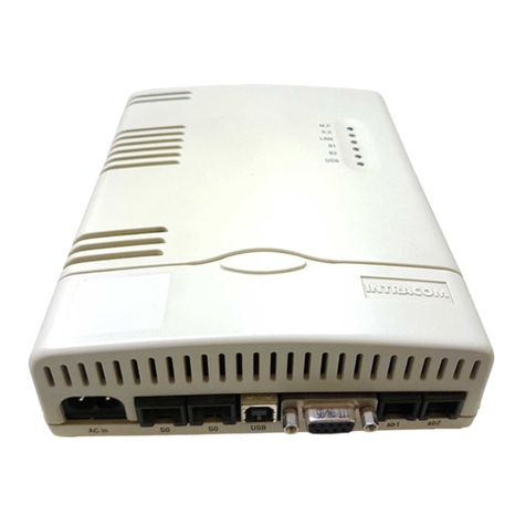
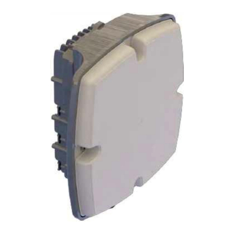
Intracom WiBAS G5 Connect+ User manual

Installation & Cabling
Edition 2.1
GDC-004/70 Confidential
Terminal stations

The information contained in this document is subject to change without prior notice.
INTRACOM S.A. TELECOM SOLUTIONS, 2022All rights reserved.
All copyright, intellectual and industrial rights in this document and in the technical knowledge it contains
are owned by INTRACOM S.A. TELECOM SOLUTIONS and/or their respective owners.
This document ismade available to the end users only for their internal use.
No part of this document nor anydata herein may be published, disclosed, copied, reproduced,
redistributed by any form or means, electronically or mechanically, or used for anyother purpose
whatsoever without the prior written approval of INTRACOM S.A. TELECOM SOLUTIONS.
Information as well as drawings and specifications contained in this document are subject to change
without prior notice.
All trademarks and copyrights mentioned herein are the property of INTRACOM S.A. TELECOM
SOLUTIONS and/or their respective owners.
Any rights notexpressly granted herein are reserved.
Printed in Greece.
INTRACOM TELECOM
19.7 km Markopoulou Ave., Peania, Athens, GR19002
T+30 210 667 1000, F +30 210 667 1001
http://www.intracom-telecom.com
email (product support): wireless-support@intracom-telecom.com

Document Revision History
WiBAS / WiBAS G5 Terminal Stations
Installation & Cabling Manual - Edition 2.1
3
Document Revision History
Revisions
This page shows the main changes effected in relation to the previous
edition of the WiBASTM / WiBASTM G5 Terminal Stations Installation &
Cabling manual.
Revisions
Previous Document Edition:
2.0
Current Document Edition:
2.1
Reasons of
change
The table below shows the main reason for the document change effected
in relation to the previous document edition:
Chapter or Paragraph
Changes
Statement: Information to the User
(page 6)
Paragraph updated.
Radio Units & Antennas Compatibility
Matrix (page 16)
Paragraph added.
Safety Precautions (page 17)
RF exposure assesment updated.
Antennas (page 31)
List of antennas updated (values).
WiBAS G5 Connect+ (page 36)
Pics of unit updated (label).

(Page intentionally left blank)

WiBAS / WiBAS G5 Terminal Stations
Installation & Cabling Manual - Edition 2.1
5
Equipment Disposal
Disposal of old electrical and electronic equipment (applicable through the
European Union and other European countries with separate waste collection
systems).
This symbol, found on this product and any of its parts or on its operating instructions
or on its packaging, indicates that electrical and electronic equipment may not be
disposed of as unsorted municipal waste. Instead, this product should be handed over
to applicable collection points for the recycling of electrical and electronic equipment.
By ensuring the correct disposal of this product, you will help prevent potential
negative consequences to the environment and human health, which could otherwise
be caused by inappropriate disposal of this product.
By recycling, reusing and other forms of recovery of old electrical and electronic
equipment you are making an important contribution to the conservation of natural
resources and to the protection of the environment.
For more information about the recycling of this product, please contact your local
municipal authorities, municipal waste disposal service or the store where you
purchased this product.
Απόρριψη παλαιών ηλεκτρικών και ηλεκτρονικών συσκευών (ισχύει στην
Ευρωπαϊκή Ένωση και άλλες Ευρωπαϊκές χώρες με συστήματα χωριστής
συλλογής απορριμμάτων).
Το σύμβολο αυτό, που απεικονίζεται πάνω στο προϊόν και σε τυχόν εξαρτήματα του
ή στο εγχειρίδιο οδηγιών του ή στη συσκευασία του, δείχνει ότι οι ηλεκτρικές και
ηλεκτρονικές συσκευές, μετά το πέρας της λειτουργίας τους, δεν θα πρέπει να
απορρίπτονται μαζί με τα αστικά απόβλητα. Αντίθετα θα πρέπει να παραδίδονται σε
κατάλληλα σημεία συλλογής για την ανακύκλωση των ηλεκτρικών και ηλεκτρονικών
συσκευών.
Διασφαλίζοντας τη σωστή απόρριψη αυτού του προϊόντος, συνεισφέρετε στην
πρόληψη πιθανών αρνητικών συνεπειών στο περιβάλλον και την ανθρώπινη υγεία,
οι οποίες θα μπορούσαν να προκληθούν από την μη ενδεδειγμένη απόρριψη του
προϊόντος.
Η ανακύκλωση, επαναχρησιμοποίηση και άλλες μορφές αξιοποίησης των παλαιών
ηλεκτρικών και ηλεκτρονικών συσκευών βοηθούν στη διαφύλαξη των φυσικών πόρων
και στην προστασία του περιβάλλοντος.
Για περισσότερες πληροφορίες σχετικά την ανακύκλωση αυτού του προϊόντος,
παρακαλούμε επικοινωνήστε με τις τοπικές δημοτικές αρχές, την υπηρεσία
αποκομιδής αστικών αποβλήτων ή το κατάστημα από το οποίο αγοράσατε το
συγκεκριμένο προϊόν.
Για περισσότερες πληροφορίες, μπορείτε να επικοινωνείτε με το Συλλογικό Σύστημα
Εναλλακτικής Διαχείρισης Αποβλήτων Ηλεκτρικού και Ηλεκτρονικού Εξοπλισμού
“Ανακύκλωση Συσκευών Α.Ε.” (www.electrocycle.gr).

WiBAS / WiBAS G5 Terminal Stations
Installation & Cabling Manual - Edition 2.1
6
Statement: Information to the User
Concerned
equipment
The statement hereinafter concerns the following equipment:
WiBASTM G5 Connect+ Terminal Station (auto polarization)
WiBASTM-Connect Terminal Station
WiBASTM-Connect Terminal Station (auto polarization)
WiBASTM OSDR-Terminal Station
Outdoor DC power injector (order code: PONE-OD-DC)
Outdoor AC power injector (order code: PONE-OD67-AC)
Outdoor DC power injector (order code: POE-HP-OD67-DC)
Continued on next page

WiBAS / WiBAS G5 Terminal Stations
Installation & Cabling Manual - Edition 2.1
7
Statement: Information to the User, Continued
WiBAS G5 Connect+
(auto polarization)
WiBAS-Connect
WiBAS-Connect
(auto-polarization)
Class B equipment
FCC Part 15.19 Statement: Information to the User
This device complies with Part 15 of the FCC Rules. Operation is
subject to the following two conditions:
(1) this device may not cause harmful interference, and
(2) this device must accept any interference received, including
interference that may cause undesired operation.
FCC Part 15.21 Statement: Information to the User
Changes or modifications made to this equipment, not expressly
approved by the party responsible for compliance, could void the user's
authority to operate the equipment.
FCC Part 15.105 Statement: Information to the User
This equipment has been tested and found to comply with the limits for
a Class B digital device, pursuant to part 15 of the FCC Rules. These
limits are designed to provide reasonable protection against harmful
interference in a residential installation. This equipment generates, uses
and can radiate radio frequency energy and, if not installed and used in
accordance with the instructions, may cause harmful interference to
radio communications.
However, there is no guarantee that interference will not occur in a
particular installation. If this equipment does cause harmful interference
to radio or television reception, which can be determined by turning the
equipment off and on, the user is encouraged to try to correct the
interference by one or more of the following measures:
Reorient or relocate the receiving antenna.
Increase the separation between the equipment and receiver.
Connect the equipment into an outlet on a circuit different from that to
which the receiver is connected.
Consult the dealer or an experienced radio/TV technician for help.
RF Exposure Statement
This equipment complies with FCC radiation exposure limits set forth for
an uncontrolled environment. This transmitter must not be co-located or
operating in conjunction with any other antenna or transmitter. In order
to avoid the possibility of exceeding the FCC radio frequency exposure
limits, this equipment should be installed and operated with minimum
distance 440 cm between the antenna and your body during normal
operation. Users must follow the specific operating instructions for
satisfying RF exposure compliance.
Continued on next page

WiBAS / WiBAS G5 Terminal Stations
Installation & Cabling Manual - Edition 2.1
8
Statement: Information to the User, Continued
WiBAS OSDR-TS
Class A equipment
EN 55022 / EN 55032:
This equipment generates, uses, and can radiate radio frequency
energy and, if not installed and used in accordance with the instruction
manual, may cause harmful interference to radio communications.
Warning: This is a Class A product according to EN 55022/EN 55032.
Operation of this equipment in a residential environment could cause
radio interference in which case the user may be required to take
adequate measures.
FCC Part 15.19:
This device complies with Part 15 of the FCC Rules. Operation is
subject to the following two conditions:
(1) this device may not cause harmful interference, and
(2) this device must accept any interference received, including
interference that may cause undesired operation.
FCC Part 15.21:
Changes or modifications made to this equipment, not expressly
approved by the party responsible for compliance, could void the user's
authority to operate the equipment.
FCC Part 15.105:
This equipment has been tested and found to comply with the limits for
a Class A digital device, pursuant to part 15 of the FCC rules.
These limits are designed to provide reasonable protection against
harmful interference when the equipment is operated in a commercial
environment.
This equipment generates, uses, and can radiate radio frequency
energy and, if not installed and used in accordance with the instruction
manual, may cause harmful interference to radio communications.
Operation of this equipment in a residential area is likely to cause
harmful interference in which case the user will be required to correct
the interference at his own.
Continued on next page

WiBAS / WiBAS G5 Terminal Stations
Installation & Cabling Manual - Edition 2.1
9
Statement: Information to the User, Continued
PONE-OD-DC
Class B equipment
EN 55022 / EN 55032:
This equipment generates, uses, and can radiate radio frequency energy
and, if not installed and used in accordance with the instruction manual,
may cause harmful interference to radio communications.
FCC Part 15.19:
This device complies with Part 15 of the FCC Rules. Operation is subject
to the following two conditions:
(1) this device may not cause harmful interference, and
(2) this device must accept any interference received, including
interference that may cause undesired operation.
FCC Part 15.21:
Changes or modifications made to this equipment, not expressly approved
by the party responsible for compliance, could void the user's authority to
operate the equipment.
FCC Part 15.105:
This equipment has been tested and found to comply with the limits for a
Class B digital device, pursuant to part 15 of the FCC Rules. These limits
are designed to provide reasonable protection against harmful interference
in a residential installation. This equipment generates, uses and can
radiate radio frequency energy and, if not installed and used in accordance
with the instructions, may cause harmful interference to radio
communications.
However, there is no guarantee that interference will not occur in a
particular installation. If this equipment does cause harmful interference to
radio or television reception, which can be determined by turning the
equipment off and on, the user is encouraged to try to correct the
interference by one or more of the following measures:
Reorient or relocate the receiving antenna.
Increase the separation between the equipment and receiver.
Connect the equipment into an outlet on a circuit different from that to
which the receiver is connected.
Consult the dealer or an experienced radio/TV technician for help.
PONE-OD67-AC
POE-HP-OD67-DC
Class B equipment
EN 55022 / EN 55032:
This equipment generates, uses, and can radiate radio frequency energy
and, if not installed and used in accordance with the instruction manual,
may cause harmful interference to radio communications.

WiBAS / WiBAS G5 Terminal Stations
Installation & Cabling Manual - Edition 2.1
10
Declaration of Conformity
English
Hereby, Intracom S.A. Telecom Solutions declares that the product
WiBASTM is CE marked in compliance with the essential requirements of
the Radio Equipment Directive 2014/53/EU, Eco Design Directives
2009/125/EC, 2017/1369/EU, RoHS directive 2011/65/EU, 2015/863/EU
and relevant amendments of the above directives.
The full text of the EU declaration of conformity is available at the
following URL: http://emc.intracom-telecom.com/en/start.htm
Δήλωση Συμμόρφωσης
Greek
Με την παρούσα, η Intracom Α.Ε. Τηλεπικοινωνιακών Λύσεων δηλώνει ότι
το προϊόν WiBASTM συμμορφώνεται με τις απαιτήσεις της οδηγίας
Ραδιοεξοπλισμού 2014/53/ΕΕ, Οικολογικού Σχεδιασμού 2009/125/EΚ,
2017/1369/ΕΕ, οδηγίας RoHS 2011/65/ΕΕ, 2015/863/EE και λοιπών
τροποποιήσεων των παραπάνω οδηγιών.
Το πλήρες κείμενο της δήλωσης συμμόρφωσης (EU) είναι διαθέσιμο στην
ακόλουθη διεύθυνση URL: http://emc.intracom-telecom.com/en/start.htm

WiBAS / WiBAS G5 Terminal Stations
Installation & Cabling Manual - Edition 2.1
11
Table of Contents
1. Introduction....................................................................................................................... 13
About this Document........................................................................................................ 13
About WiBAS Terminal Stations....................................................................................... 15
Radio Units & Antennas Compatibility Matrix.................................................................... 16
Safety Precautions........................................................................................................... 17
2. Materials ............................................................................................................................ 30
3. Before Starting the Installation ........................................................................................ 35
3.1. Radio Unit Connection Points........................................................................................... 35
WiBAS G5 Connect+........................................................................................................ 36
WiBAS-Connect ............................................................................................................... 39
WiBAS OSDR-TS............................................................................................................. 46
3.2. Radio Unit Cabling Overview............................................................................................ 49
Gigabit ETH cable for service Traffic, Inband Management and Powering ....................... 50
3.3. Site Prerequisites............................................................................................................. 58
3.4. Recommended Installation Tools ..................................................................................... 61
4. Installation Procedures..................................................................................................... 63
4.1. Installing Radio Units and Antennas................................................................................. 64
WiBAS G5 Connect+ Combo ........................................................................................... 65
WiBAS-Connect Combo................................................................................................... 74
WiBAS-Connect and Low Profile 0.3 m / 0.5 m................................................................. 97
WiBAS-Connect and Parabolic 0.3 m with Adaptation Plate / 0.6 m with Clamps........... 110
WiBAS-Connect and Panel............................................................................................. 124
WiBAS OSDR-TS and Parabolic 0.3 m .......................................................................... 140
WiBAS OSDR-TS and Panel.......................................................................................... 144
4.2. Installing Radio Units Cables.......................................................................................... 157
Grounding Cable............................................................................................................ 158
ETH Cable...................................................................................................................... 162
Cable Holder .................................................................................................................. 170
Appendix A - Installing Power Injectors............................................................................ 173
POE-AC75-ID / POE-ID-AC72 / POE-AC56-IDH / POE-ID-AC35................................... 174
PONE-OD67-AC ............................................................................................................ 181
PONE-OD-DC................................................................................................................ 188
POE-HP-OD67-DC......................................................................................................... 198
Appendix B –Terminating Cables ..................................................................................... 203
Ethernet (S-FTP)............................................................................................................ 204
Grounding ...................................................................................................................... 209
Power............................................................................................................................. 212

(Page intentionally left blank)

WiBAS / WiBAS G5 Terminal Stations
Installation & Cabling Manual - Edition 2.1
13
1. Introduction
About this Document
Scope of
document
The scope of this document is to provide detailed instructions to the
installation and cabling of the following wireless PtMP / PtP Terminal
Station products:
WiBASTM G5 Connect+ (auto polarization)
WiBASTM –Connect (single & auto polarization)
WiBASTM OSDR-TS
OSDR is an Outdoor Software-Defined Radio platform. The same
radio unit, based on software running is capable to operate, as
follows:
PtMP Terminal Station: WiBASTM OSDR-TS.
PtMP Base Station: WiBASTM OSDR-HUB.
PtP Node: OmniBASTM OSDR.
WiBASTM G5 Connect+ can operate as follows:
PtMP Terminal Station
PtP Node
Continued on next page

1.Introduction
14
About this Document, Continued
Target
audience
This document is addressed to certified technicians with wireless
equipment knowledge and skills concerning the following:
Outdoor Radio Unit pole / tower / wall installation.
Antenna with mounting kit installation.
Preparation & Termination of: Ethernet & Grounding cables.
Laying and Installation of: Ethernet, Fiber Optic & Grounding cables.
Testing Ethernet cables using Ethernet testers.
Reference
manuals
The listed reference manuals in the table below maybe are useful during
installation process:
WiBASTM / WiBASTM System Description.
WiBASTM / WiBASTM G5 Product Catalog.
WiBASTM / WiBASTM Startup & Commissioning.
Lightning & Surge Protection for Intracom Telecom Radios –Installation
Practices.
Lightning & Surge Protector (LSP) Datasheet.
Document
conventions
This document applies to the following conventions:
Bold blue fonts are used for order codes.
Blue underline fonts are used for references.
Bold black fonts are used for indicating important information or
paragraph header.
This symbol means DANGER. The purpose of this symbol is to warn you
that any wrong action can cause bodily injury or even death.
This symbol means CAUTION. The purpose of this symbol is to prevent
you from performing an action that might result in damage of the
equipment.
The purpose of this symbol is to protect you from unauthorized entry to
the site and damage your equipment.
A note calls your attention to important supplementary information.
A hint denotes helpful piece of advice or practical suggestion.

WiBAS / WiBAS G5 Terminal Stations
Installation & Cabling Manual - Edition 2.1
15
About WiBAS Terminal Stations
Product
installation
overview
WiBASTM solution provides high flexibility and with zero-footprint
installation, through a wide variety of compact Terminal Station radio unit
and smart-design antenna options, as shown below:

1.Introduction
16
Radio Units & Antennas Compatibility Matrix
Product
installation
overview
WiBASTM solution provides high flexibility, through a wide variety of compact
Terminal Station radio units combined with multiple antenna options facilitating
demanding coverage scenarios. The following table presents a compatibility
matrix between the radio units form factors and the available antennas.
WiBASTM Terminal Station Form Factors
/ Frequency (GHz)
Single Polarization
Automatic Polarization
OSDR-TS
Connect
Connect
G5 Connect+
10.5
26
28
32
10.5
26
28
28
24 / 27 / 28
Antennas Order Codes
ANT-IS-2628-1F-C
-
-
-
-
-
√
√
-
-
ANT-IS-2628-1D6F-C
-
-
-
-
-
√
√
-
-
ANT-IS-2628-2F-C
-
-
-
-
-
√
√
-
-
ANT-DP-2628-1F-C
-
-
-
-
-
-
-
√
√
ANT-DP-2628-1D6F-C
-
-
-
-
-
-
-
√
√
ANT-DP-2628-2F-C
-
-
-
-
-
-
-
√
√
ANT-IS-11-PL-C
√
-
-
-
√
-
-
-
-
ANT-IS-10-1F-C
-
-
-
-
√
-
-
-
-
ANT-IS-11-2F
ANT-IS-11-3F
ANT-IS-11-4F
ANT-IS-11-6F
√
-
-
-
√
-
-
-
-
ANT-IS-26-1F
ANT-IS-26-2F
ANT-IS-26-3F
ANT-IS-26-4F
-
√
-
-
-
√
-
-
-
ANT-IS-28-1F
ANT-IS-28-2F
ANT-IS-28-3F
ANT-IS-28-4F
-
-
√
-
-
-
√
-
-
ANT-IS-32-1F
ANT-IS-32-2F
ANT-IS-32-3F
-
-
-
√
-
-
-
-
-

WiBAS / WiBAS G5 Terminal Stations
Installation & Cabling Manual - Edition 2.1
17
Safety Precautions
RF exposure
assessment
Introduction
Any Radio Equipment is emitting Radio Frequency (RF) Radiation through
its antenna which may be integrated to the equipment or not. It is
important to follow any local, national or international regulation during
installation and operation of the Radio Equipment to avoid radiation
hazards.
Regulations
A lot of countries have issued and follow their own regulations but others
adopted European or international regulations, standards or guidelines.
In Europe, some countries follow the recommendations included in
1999/519/EC directive which is based on the guidelines document
published by the International Commission on Non-Ionizing Radiation
Protection (ICNIRP). Other countries have issued their own regulations for
this purpose.
The above mentioned European Directive provides the reference levels
(limits) for assessment of the human exposure to electromagnetic fields
based on health effects. European Union, FCC (US) and Industry Canada
Reference Levels for microwave frequencies applied to INTRACOM
Telecom equipment are given in the following table (Table 1).
Table 1: RF Exposure Reference Levels
Regulation
Frequency Range
Power Density
Notes
1999/519/EC
2-300 GHz
10 W/m2
General Public
FCC 1.1310
1.5-100 GHz
1 mW/cm2
(10 W/m2)
General Public
FCC 1.1310
1.5-100 GHz
5 mW/cm2
(50 W/m2)
Occupational
IC RSS-102
6-150 GHz
1 mW/cm2
(10 W/m2)
General Public
IC RSS-102
6-150 GHz
5 mW/cm2
(50 W/m2)
Occupational
Continued on next page

1. Introduction
18
Safety Precautions, Continued
RF exposure
assessment,
continued
RF Exposure General Guidelines for equipment installation
As a general rule it is expected that the highest level of emission would be
in line of sight and in close vicinity of the antenna. Additional requirements
for the installation of equipment shall be as follows:
The equipment should be located in such a way to prevent the public from
accessing the area where the RF Radiation exceeds the regulation limits.
For this, a compliance boundary is determined, based on its radio
characteristics. Outside this area the RF radiation levels are below the
reference levels (limits).
Operation and maintenance personnel, which have to work within the RF
radiation compliance boundary area, should be informed about the source
of radiation and should have the capability to power off the radio
equipment before entering the compliance boundary area.
The compliance boundary area should be defined by a relevant warning
sign or physical barrier.
Radiation Exposure Assessment –Compliance Boundary Calculation
In order to calculate the RF exposure compliance boundary around a Radio
Equipment and its antenna, a theoretical approach is described below. As
the installation environment could be complex, i.e obstacles causing
reflections or scattering, soil conditions etc., this approach may be used to
provide a rough estimation of the expected exposure in power flux density
on a certain point. More precise estimations can be feasible if detailed
knowledge of the installation environment is available. In some cases a
safety factor can be used to increase the level of confidence.
The power flux density Scan be calculated using the following formula:
S=P*Gnum / (4*r2*π)
where,
P= is the maximum power at the antenna port of the Radio Equipment,
Gnum = is the numerical gain of the antenna,
r = is the distance between the antenna and the point of interest.
Continued on next page

WiBAS / WiBAS G5 Terminal Stations
Installation & Cabling Manual - Edition 2.1
19
Safety Precautions, Continued
RF exposure
assessment,
continued
Specification
Value / Description
Radio Unit
Type
WiBASTM-Connect
Frequency, GHz
28
Antenna
Type
Low profile parabolic
Diameter, m
0.3
Gain, dBi
37.5
Parameter
Power Flux Density Limit, W/m2(General Public)
10.0
Compliance Boundary, m (General Public)
1.38
Power Flux Density Limit, W/m2(Occupational)
50.0
Compliance Boundary, m (Occupational)
0.62
Specification
Value / Description
Radio Unit
Type
WiBASTM-Connect
Frequency, GHz
26
Antenna
Type
Low profile parabolic
Diameter (m)
0.3
Gain, dBi
37.0
Parameter
Power Flux Density Limit, W/m2(General Public)
10.0
Compliance Boundary, m (General Public)
1.20
Power Flux Density Limit, W/m2(Occupational)
50.0
Compliance Boundary, m (Occupational)
0.54
Continued on next page

1. Introduction
20
Safety Precautions, Continued
RF exposure
assessment,
continued
Specification
Value / Description
Radio Unit
Type
WiBASTM-Connect
Frequency, GHz
10.5
Antenna
Type
Low profile parabolic
Diameter, m
0.3
Gain, dBi
29.5
Parameter
Power Flux Density Limit, W/m2(General Public)
10.0
Compliance Boundary, m (General Public)
0.87
Power Flux Density Limit, W/m2(Occupational)
50.0
Compliance Boundary, m (Occupational)
0.39
Continued on next page
This manual suits for next models
5
Table of contents
Other Intracom Network Hardware manuals
Popular Network Hardware manuals by other brands

FLIR
FLIR VIEWCOM/E MAX+ Setup guide

Seiko
Seiko NS-2250 Command reference

Advanced
Advanced AxisAX AX-PENN Installation & operation manual

Tosibox
Tosibox 350 quick start guide

HP
HP AdvanceStack Hub-8U J2610B Hardware installation and reference guide

TerraMaster
TerraMaster F5-421 Fundamentals and Preliminaries

Lindy
Lindy 32164 user manual

Cambium Networks
Cambium Networks RFU-C installation guide

M86 Security
M86 Security M86 Threat Analysis Reporter user guide

Cisco
Cisco LightStream 1010 Configuration guide

Digital Voice Systems
Digital Voice Systems Net-2000-P25 Specifications

Costar
Costar CR4020XDI installation manual