M550004-01
ii
LIST OF FIGURES
Figure 2-1 Outline Drawing, 2kW to 3kW (Output Voltage <=60 V)..........................................................2-5
Figure 2-2 Outline Drawing, 2kW to 3kW (Output Voltage >=80 V)..........................................................2-6
Figure 2-3 Outline Drawing, 3.3kW to 15kW (Output Voltage <=60 V).....................................................2-7
Figure 2-4 Outline Drawing, 3.3kW to 15kW (Output Voltage >=80 V).....................................................2-8
Figure 2-5 Outline Drawing, 13.3kW & 16kW to 30kW (Output Voltage <=60 V)......................................2-9
Figure 2-6 Outline Drawing, 13.3kW & 16kW to 30kW (Output Voltage >=80 V)....................................2-10
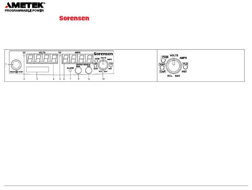
Figure 3-1 DHP Series Controls and Indicators.........................................................................................3-1
Figure 3-2 Pin-out for Connector J1...........................................................................................................3-8
Figure 3-3 Remote Current Programming Using Resistance..................................................................3-11
Figure 3-4 Remote Current Programming Using 0-5 or 0-10 VDC Source.............................................3-11
Figure 3-5 Remote Voltage Programming Using Resistance..................................................................3-12
Figure 3-6 Remote Voltage Programming Using 0-5 or 0-10 VDC Source.............................................3-12
Figure 3-7a Remote Sensing Operation at the Load...............................................................................3-13
Figure 3-8b Remote Sensing Operation at the Load ≤ 60V Out..............................................................3-13
Figure 3-9 Remote On/Off Control by Contact Closure...........................................................................3-14
Figure 3-10 Remote On/Off Using Isolated AC or DC Voltage Source ...................................................3-14
Figure 3-11 Remote On/Off Using Isolated TTL/CMOS Voltage Supply.................................................3-15
Figure 3-12 Remote Overvoltage Set Using DC Voltage Source............................................................3-15
Figure 4-1 Auto-step Programming Screen...............................................................................................4-1
Figure 4-2 Auto-step Programming Menu System ....................................................................................4-2
Figure 4-3 Programming Start Screen.......................................................................................................4-3
Figure 4-4 Control Source Menu................................................................................................................4-4
Figure 4-5 Control Source – Auto-step......................................................................................................4-4
Figure 4-6 Auto-step Activation Screen.....................................................................................................4-4
Figure 5-1 Power Supply Calibration Screen.............................................................................................5-1
Figure 5-2 Calibration Abort Screen ..........................................................................................................5-2
Figure 5-3 Prepare Shunt Screen..............................................................................................................5-2
Figure 5-4 Current Calibration 1 ................................................................................................................5-2
Figure 5-5 Hot Shunt Warning Screen.......................................................................................................5-3
Figure 5-6 Current Calibration 2 ................................................................................................................5-3
Figure 5-7 Prepare Load Screen ...............................................................................................................5-4
Figure 5-8 Voltage Calibration 1................................................................................................................5-4
Figure 5-9 High Voltage Warning Screen..................................................................................................5-4
Figure 5-10 Voltage Calibration 2..............................................................................................................5-5
Figure 5-11 Accept Calibration Screen......................................................................................................5-5
LIST OF TABLES
Table 1-1 2 kW to 3 kW Series Technical Characteristics.........................................................................1-2
Table 1-2 5kW to 15kW and 16kW to 30kW Series Technical Characteristics.........................................1-4
Table 1-3 Available Voltages and Currents...............................................................................................1-6
Table 2-1 2kW to 3kW High Series Input/Output Connectors ...................................................................2-2
Table 2-2 5kW to 15kW and 16kW to 30kW Series Input/Output Connectors..........................................2-2
Table 2-3 Output Connection Descriptions*...............................................................................................2-3
Table 2-4 Input Connection Descriptions...................................................................................................2-3
Table 2-5 Maximum AC Current Ratings...................................................................................................2-3
Table 2-6 Minimum Wire SizeTable...........................................................................................................2-4
Table 3-1 2U, 3U and 6U High Series Controls and Indicators.................................................................3-1
Table 3-2 J1 Designations and Functions..................................................................................................3-6
Table 6-1 Preventive Maintenance Schedule............................................................................................6-1
Table 6-2 Inspection and Corrective Action...............................................................................................6-2