Ametek Gemco 2120 User manual

R
ESOLVER
& LDT I
NTERFACING
2120
PLC Interface Module
Series 956
ABSOLUTE PROCESS CONTROL
KNOW WHERE YOU ARE... REGARDLESS
INSTALLATION MANUAL
Series 2120
2120 Manual Z71.indd 12120 Manual Z71.indd 1 8/22/2005 8:32:38 AM8/22/2005 8:32:38 AM
Spec Tech Industrial Electric
www.spectechind.com
888-773-2832
Spec Tech Industrial Electric
www.spectechind.com
888-773-2832

i Installation and Programming Manual
1080 North Crooks Road
Clawson, MI 48017-1097
Phone (248) 435-0700
FAX (248) 435-8120
Internet www.ametekapt.com
www.ametek.com
Copyright 1997, 1998, 1999, 2001 by AMETEK
All Rights Reserved - Made in the U.S.A.
Version 0.3
AMETEK has checked the accuracy of this manual at the time it was printed. Any comments you may
have for the improvement of this manual are welcomed.
AMETEK reserves the right to revise and redistribute the entire contents or selected pages of this manual.
All rights to the contents of this manual are reserved by AMETEK.
Preface
This manual is divided into four parts. Part 1 provides an introduction for the Theory and
Operation of the Series 2120 PLC Interface Module. Part 2 contains a Hardware Overview.
Part 3 explains the Mounting and Wiring of the 2120 PLC Interface Module. Part 4 provides
the Programming Instructions. Also included are four Appendixes; Error Messages, Function
Summary Chart, Catalog Numbering System, and Specifi cations. A glossary and index are also
provided at the back of this manual.
Disconnect power before servicing. The Gemco Series 2120 contains no servicable
components other than the power supply fuse. Consult factory for repair or replacement.
Spec Tech Industrial Electric
www.spectechind.com
888-773-2832
Spec Tech Industrial Electric
www.spectechind.com
888-773-2832

Installation and Programming Manual ii
Contents
Chapter 1: Theory of Operation 1
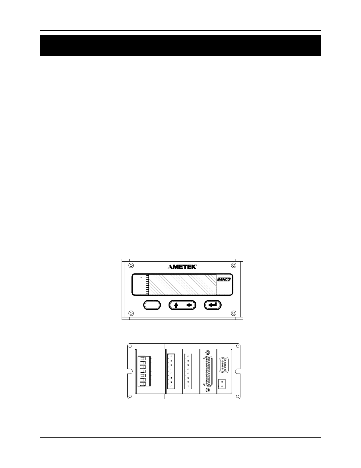
Chapter 2: Hardware Overview 2
2.1 tandard Modules ..................................................................................................................... 3
Controller (FMMP01) ......................................................................................................... 3
Power upply (FMP 01) .................................................................................................... 3
2.2 Input/Output Module ............................................................................................................... 3
Resolver (FMIR01) ............................................................................................................. 3
Variable Pulse (FMIP01)..................................................................................................... 4
LDT Input (FMIP020) ........................................................................................................ 4
Digital Output (FMOD01) .................................................................................................. 4
Analog Output (FMOA01).................................................................................................. 4
Relay Output (FMOR01) .................................................................................................... 5
2.3 tatus LEDs Defi ned ................................................................................................................ 5
Chapter 3: Mounting and Wiring 7
Things to Consider ..............................................................................................................7
3.1 Mounting ................................................................................................................................. 7
Interface Module ................................................................................................................. 7
Cabling ................................................................................................................................ 8
3.2 Wiring ..................................................................................................................................... 10
Controller Module (FMMP01).......................................................................................... 10
Relay Output Module (FMOR01)..................................................................................... 10
Power upply Module (FMP 01)..................................................................................... 11
Resolver Module (FMIR01).............................................................................................. 12
Variable Pulse LDT Module (FMIP01)............................................................................. 12
LDT Input (FMIP02) ........................................................................................................ 13
Digital Output (FMOD01) ................................................................................................ 13
Analog Output (FMOA01)................................................................................................ 14
Chapter 4: Programming 21
Before You tart ................................................................................................................21
Programming Keys Defi ned .............................................................................................. 22
4.1 Resolver Input Confi guration Functions................................................................................. 23
cale Factor (300) ............................................................................................................. 23
Turns Counting (301) ........................................................................................................ 23
Turns Counting Wrap Around (308) ................................................................................. 24
Position Offset (302) ......................................................................................................... 24
Programming cale Factor (300) ...................................................................................... 24
Display Power-Up (305) ................................................................................................... 26
Resolver Reset-to-Preset (307) ......................................................................................... 26
Spec Tech Industrial Electric
www.spectechind.com
888-773-2832
Spec Tech Industrial Electric
www.spectechind.com
888-773-2832

iii Installation and Programming Manual
4.2 : LDT Confi guration Functions..........................................................................................27
Wire S eed (300) .............................................................................................................. 28
Count Direction (301) ....................................................................................................... 28
Position Offset (302) ......................................................................................................... 29
Fault Pulse Time (306) ...................................................................................................... 30
LDT Out ut Ty e (307) .................................................................................................... 30
LDT L1 In ut Reset-to-Preset (311)................................................................................. 31
4.3 : Monitor Setu Functions .................................................................................................31
Unit of Measurement (14)................................................................................................. 31
Decimal Location (13) ...................................................................................................... 32
Position Hold (15)............................................................................................................. 32
Auxiliary LED (16)........................................................................................................... 33
Move Detection Time-Out(12).......................................................................................... 34
4.4: Relay Setu Functions ......................................................................................................34
U er End Limit (400)...................................................................................................... 35
Lower End Limit (401) ..................................................................................................... 35
Relay State (402)...............................................................................................................36
Relay Override (403)......................................................................................................... 36
4.5: Digital Out uts..................................................................................................................37
Out ut Ty e (200) ............................................................................................................. 37
Latch/Synchronize Handshake (201) ................................................................................ 37
Logic Level (202).............................................................................................................. 38
Error Condition Out ut State (203) .................................................................................. 38
4.6: Analog Out uts ................................................................................................................39
Analog Out ut Channel 1 ................................................................................................. 39
Analog Out ut Channel 2 ................................................................................................. 42
4.7: Program and Su ervisory Mode Functions .....................................................................43
Program Mode Access (10)............................................................................................... 43
Program Mode Time-out (11) ........................................................................................... 44
A endix A: Error Messages 45
Error Conditions (306) ...................................................................................................... 50
A endix B: Function Summary Chart 51
A endix C: Catalog Numbering System 53
A endix D: S ecifi cations 54
Glossary ............................................................................................................................ 56
Index.................................................................................................................................. 58
Spec Tech Industrial Electric
www.spectechind.com
888-773-2832
Spec Tech Industrial Electric
www.spectechind.com
888-773-2832

1
Installation and Programming Manual
Chapter 1: Theory of Operation
The Gemco Series 2120 P C Interface Module converts the input signal from a resolver based
rotary transducer or Magnetostrictive inear Displacement Transducer ( DT) to digital analog or
overtravel relay outputs. Resolver based inputs provide up to 14 bit resolution per turn with a
fi eld programmable scale factor. DT based inputs allow fi eld selection of position data in inches
to .001 inches or millimeters to .01 millimeter. The module’s 6 digit display can show position
or velocity data. The optional 20 bit digital output board allows fi eld confi guration of parallel
digital outputs in a binary, BCD or grey code format. The optional analog output board allows
fi eld selection of a voltage or current output of position or velocity and is scalable over any
portion of the displayed data. The optional relay output board provides two mechanical relay
outputs intended for use as overtravel limits.
Advanced features include:
Reset-to-Preset input for continuous recalibration or compensation for process
drift.
Turns counting software for multiple turn applications using a single turn resolver.
Move detection software for detection of a jammed motor driven mechanism or
drive component failure.
Position hold input to freeze displayed data during high vibration periods at the
sensor.
Field programmed data is protected by a hard contact closure on the back of the module and a
user selectable security code.
Chapter 1: Theory of Operation
Spec Tech Industrial Electric
www.spectechind.com
888-773-2832
Spec Tech Industrial Electric
www.spectechind.com
888-773-2832

2Installation and Programming Manual
Chapter 2: Hardware Overview
Figure 2-1 Interface Module with Resolver/Digital Modules
his chapter contains descriptions of the Interface Module’s components. For installation
instructions, see Chapter 3: Mounting and Wiring.
he Interface Module contains a heavy-duty case which can hold up to fi ve modules. Several
optional modules can be used with the Interface Module. See also Appendix C: Catalog
Numbering System for more information on optional modules.
Power Supply
Controller (CPU)
Digital Output (optional)
Analog Output (optional)
Resolver Input (optional)
Linear Displacement ransducer L1 (optional)
Linear Displacement ransducer V1 (optional)
Relay Output (optional)
he Interface Module’s faceplate contains a 6-digit, seven-segment LED display and four
programming keys. he LED display is used to indicate the position, as well as to display
parameters when programming. he programming keys are used to program the Interface
Module. en small status LEDs are also provided. hese LEDs are used to indicate the state
of the monitor during machine operation.
Chapter 2: Hardware Overview
AUX3
AUX2
AUX1
PROGRAM
FLT OK
MVT FLT
POS
UPR LIM
LWR LIM
RPM
2120
SERIES
F()
3
FMIR01
3
RSLVR
}
7
POWER
FMPS01
FMOR01
4
}
POWER
POWER SUPPLY
100-240VAC 50/60 Z
3 5 6412
RELAY
GND
AUX INP
FLT C K
L1
L2
Y
A
L
R
E
4
U
FMMP01
2
T
1
C.P.U.
S
V
R
E
L
O
E
R
P
T
O
U
G
T
L
D
2 1
BACK
FRONT
Spec Tech Industrial Electric
www.spectechind.com
888-773-2832
Spec Tech Industrial Electric
www.spectechind.com
888-773-2832

Installation and Programming Manual
Chapter 2: Hardware Overview
3
2.2: Input/Output Modules
2.1: Standard Modules
his section provides descriptions of basic Interface Modules (also see Section 2.2: Input/Output
Modules).
Controller (FMMP01)
his module contains the Central Processing Unit (CPU) which is used to process data it receives from
the resolver or Linear Displacement ransducer (LD ). It then shows the position on the Interface
display. he controller is also responsible for continuously monitoring all programmed setpoints and
timing functions. o store programmed functions, including fi xed settings, the controller contains
battery-backed memory. his battery requires no maintenance and is non-replaceable. o allow for
remote communications with the Interface Module, RS-232 and RS-485 serial ports are available through
a D9 connector. he controller is located in slot 1 of the enclosure. (For wiring instructions, see Section
3.2: Wiring)
Power Supply (FMPS01)
his module supplies power to the Interface Module. It also contains a fault check relay and an auxiliary
input. he fault check relay is designed to take power away from the operating machine when a fault
occurs during machine operation, or when power is taken away from the Interface Module. In order for
this to perform it’s intended function, the fault check relay must be properly wired to the machine’s safety
interlock. For a listing of errors which will cause the fault check relay to deenergize, see Chart A-4 in
Appendix A: Error Messages. he auxiliary input is designed for the Move Detection ime-out and
Position Hold functions and accepts an 85-265 VAC input signal. he power supply is located in slot 5 of
the enclosure. (For wiring instructions, see Section 3.2: Wiring.)
he PLC Interface Module can be used with a resolver or Linear Displacement ransducer (LD ). Either
input module will be located in slot 3 of the enclosure. You can identify the module type by the name
found on the back of the module.
Resolver (FMIR01) Input Option R1
his module is used with a Gemco resolver. he resolver assembly consists of a highly accurate and
repeatable brushless resolver, housed in an industrial-grade enclosure. he shaft position is calculated
from two analog signals that vary as a function of the angular rotation of the input shaft.
he brushless resolver works on the same principle as a rotary transformer to couple power into the rotor.
he construction of the brushless resolver consists of a two-phase stator and a single-phase rotor. Each
stator is positioned 90° apart from each other. he two stators continually provide two different output
voltages. Using these two outputs, the module performs a ratiometric conversion and provides an absolute
position. his results in a highly accurate and repeatable transducer having excellent reliability with an
infi nite resolution which can be converted by a resolver-to-digital converter into digital position data. his
module also provides the reset-to-preset input terminals. An input at these terminals will reset the position
display and outputs to a preprogrammed value. his input can be used to continuously compensate for
position drift caused by slippage in the drive mechanism turning the resolver.
Spec Tech Industrial Electric
www.spectechind.com
888-773-2832
Spec Tech Industrial Electric
www.spectechind.com
888-773-2832

4Installation and Programming Manual
Chapter 2: Hardware Overview
Variable Pulse (FMIP01) Input Option V1
This module is used with an LDT that provides its output in the form of a pulse width modulated S-422
signal. This module only works with Gemco Series 951VP2110 LDT’s.
LDT Input (FMIP02) Input Option L1
This module will accept an output from a controlled pulse, start stop pulse or variable pulse
magnetostructive LDT. This card accepts a wide range of LDT inputs and provides faster updates than
the variable pulse version described above.
It allows the PLC Interface Module to receive the signals from the LDT. The pulse width signal is
converted to position data which the monitor displays. The module also provides +24 VDC to supply
power to the LDT. The module was designed to work with the Gemco Series 951 or 952CP or S LDT.
However, other LDTs can be used with the module. If you are using a different type of LDT, contact the
factory for wiring and programming instructions.
This module also contains reset-to-preset input terminals. A signal at this input will reset the position
display and outputs to a preprogrammed value. This feature is useful for quick recalibration of the
system to a gauge block or known machine position.
Digital Output (FMOD01) Output Option D1, D2 or D3
This module is used to transmit parallel digital output data to a PLC or personal computer. The digital
output is fi eld confi gurable for position or velocity data in a binary, BCD or grey code format. This data
is updated every 50 microseconds. The electrical characteristics of this output data can be current sinking,
current sourcing or TTL which must be specifi ed in the module’s part number.
This module also provides two input pins for use as a fi eld confi gured latch or synchronized handshake
input. The latch input freezes the digital output data while the PLC reads it. The data is updated when the
input is released. When confi gured for synchronized handshake, the PLC must provide a clocked square
wave input into these input pins. Digital data is updated on each transition of the square wave and the PLC
is synchronized to read the updated position data after a 100 microsecond settling time.
This input accepts a 5 to 24 VDC source from the PLC to perform the latch or synchronized handshake
function described above. For details on wiring to the digital output board, see pages 17 & 18.
Analog Output (FMOA01) Output Option A1
This module is used to transmit position or velocity data to a PLC in an analog format. The module
provides two separate analog output channels that can be independently confi gured for position or
velocity data.
These analog outputs can be fi eld scaled over any range and confi gured for 0 - 10 VDC, 10 - 0 VDC,
-10 VDC to +10 VDC, 4 - 20 mA, 20 - 4 mA, 0 - 20 ma or 20 - 0 mA.
For applications that require remote indication it is recommended to use an aftermarket analog input
display or a digital input display. When using one of these displays the optional analog or digital output
board must be specifi ed in the part number.
Spec Tech Industrial Electric
www.spectechind.com
888-773-2832
Spec Tech Industrial Electric
www.spectechind.com
888-773-2832

Installation and Programming Manual
Chapter 2: Hardware Overview
5
2.3: Status L Ds Defi ned
The Interface Module has 10 status L Ds and four programming keys. The L Ds provide information on
the monitor’s state during machine operation, and the programming keys are used to program functions
and perform basic operations.
Figure 2-2 Status L Ds and Programming Keys
PROGRAM The program L D turns on when the Interface Module is in program mode and
turns off when it is not. Functions cannot be programmed when this L D is off.
FAULT OK The fault check OK L D turns on when the power supply’s fault check relay is
energized, indicating the system is OK. This L D will turn off when a fault is
detected, indicating that the fault check relay is deenergized.
MVT FLT The movement fault L D turns on when a movement fault is detected. (For more
information, see Move Detection Time-out in Section 4.3: Setup Functions.)
Relay Output (FMOR01)
This optional module contains two overtravel limit relays. These relays can be programmed to either
energize or deenergize upon reaching the programmed overtravel position. These relays will also actuate
upon detection of the system and operating errors listed in chart A-5 in Appendix A.
Status LEDs
Shift Key
Scroll Key
Function Key
Enter Key
AUX 3
AUX 2
AUX 1
PROGRAM
FLT OK
MVT FLT
POSITION
UPR LIM
LWR LIM
RPM
2120
SERIES
F()
Spec Tech Industrial Electric
www.spectechind.com
888-773-2832
Spec Tech Industrial Electric
www.spectechind.com
888-773-2832

6Installation and Programming Manual
Chapter 2: Hardware Overview
POSITION This position LED turns on when the Inter ace Module is showing position in the
large LED display.
RPM The RPM LED turns on when the Inter ace Module is showing RPM in the large
LED display.
UPR LIM The upper limit LED refl ects the state o the relay when the value programmed in
the Upper End Limit unction is reached. The relay can be programmed to energize
or deenergize upon reaching the programmed overtravel position. (For more
in ormation, see Upper End Limit in Section 4.3: Setup Function).
LWR LIM The lower limit LED refl ects the state o the relay when the value programmed in
the Lower End Limit unction is reached. The relay can be programmed to
energize or deenergize upon reaching the programmed overtravel position. (For
more in ormation, see Lower End Limit in Section 4.3: Setup Functions.)
AUX 1 For uture expansion.
AUX 2 For uture expansion.
AUX 3 The auxiliary LED is programmable and can be used with the Position Hold
unction. When enabled, this LED indicates when the position is being held. (For
more in ormation, see Position Hold and Auxiliary LED in Section 4.3: Setup
Functions.)
The unction key is used to begin a process or programming a unction. When
this key is pressed, the Inter ace Module prepares itsel or the entry o a specifi c
unction number.
The scroll key is used to scroll through the Inter ace Module’s list o unction
numbers, as well as other lists. This key is also used to increment selected digits
shown on the Inter ace Module’s LED display.
The shi t key is used to move to (select) a specifi c digit shown on the Inter ace
Module’s LED display rom right to le t.
The enter key is selected a ter a unction number has been entered. This begins
the programming process or the selected unction. The enter key is also used to
program a value in a unction.
NOTE: For more in ormation on how to use the programming keys, see Chapter 4: Programming
(F)
Spec Tech Industrial Electric
www.spectechind.com
888-773-2832
Spec Tech Industrial Electric
www.spectechind.com
888-773-2832

Installation and Programming Manual
Chapter 3: Mounting and Wiring
7
This chapter provides instructions for mounting and wiring the PLC Interface Module. These instructions
have een divided into two sections: Section 3.1: Mounting and Section 3.2: Wiring.
Things to Consider
It is recommended that you consider the following efore installing the PLC Interface Module:
To minimize the effects of electromagnetic interference (EMI), the monitor should e
mounted as far away as possi le from motor starters, drives and control relays.
The monitor should e mounted in an area free of water spray, corrosive gases, fl ying
chips, or any other foreign matter that could cause damage to the unit.
If the module is mounted directly on the machine, it should e installed in an area
where shock and vi ration will e minimized.
The module should e located in an area that is within the temperature and humidity
specifi cations. (See Appendix D: Specifi cations.)
3.1: Mounting
Interface Module
To assist you in mounting the PLC Interface Module, refer to Figure 3-1. Perform the following steps:
1. According to the dimensions as shown in Figure 3-1, cut out a section of the panel
you wish to mount the module in.
2. Remove the mounting rails on the left and right side of the unit y removing the
#6-32 UNC screws located on the rear of the unit.
3. Place the module in the cutout section of the panel.
4. From ehind the panel, insert the two mounting rails into the module’s side grooves.
The feet of the rails must e inserted fi rst. See Figure 3-1 for the location of the
mounting rails.
The mounting rails secure the monitor y their feet eing pressed against the ack
of the panel.
Chapter 3: Mounting and Wiring
Spec Tech Industrial Electric
www.spectechind.com
888-773-2832
Spec Tech Industrial Electric
www.spectechind.com
888-773-2832

8Installation and Programming Manual
Chapter 3: Mounting and Wiring
5. Insert each #6-32 NC screw into each of the module’s screw holes.
6. sing a 7/64" Allen wrench, secure the screws into position. This will secure the
mounting rails. 8 to 10 inch pounds of torque is required.
Cabling
The signals from a resolver or LDT are inherently very immune to electrical noise. However, to ensure
trouble free operation in an industrial environment, it is recommended that these cables be routed in a
separate conduit isolated from all power handling leads. A continuous uninterrupted length of cable from
the transducer to the Interface Module is preferred. If fi eld splices to the cable are required, they must
be done in an isolated grounded junction box with no other power handling leads present. Shielded cable
must be used that has similar shielding as the standard Gemco cable and the shield must not be tied to
ground anywhere along the cable run except as shown in the wiring diagram in this manual.
The cabling should also be routed away from noise generating devices like variable frequency drives,
servo amplifi ers, solenoid valves or large contactors.
Spec Tech Industrial Electric
www.spectechind.com
888-773-2832
Spec Tech Industrial Electric
www.spectechind.com
888-773-2832

Installation and Programming Manual
Chapter 3: Mounting and Wiring
9
Figure 3-1 Dimensional Drawing
Drawing E0232200
AUX 3
AUX 2
AUX 1
PROGRAM
FLT OK
MVT FLT
POSITION
UPR LIM
LWR LIM
RPM
2120
SERIES
2.67
2.61
3.00
2.00 TYP
6.50
5.32 CASE WIDTH
6.00
5.3
.50 5.53
RECOMMENDED
PANEL CUTOUT
MOUNTING RAIL W/ FOOT
ALUMINUM CASE
3/ DIN STD
ALUMINUM BEZEL
1/ " GASKET DEPLUGGABLE
TERMINAL STRIPS
F
()
MOUNTING RAIL FOOT
MOUNTING SCREWS
Spec Tech Industrial Electric
www.spectechind.com
888-773-2832
Spec Tech Industrial Electric
www.spectechind.com
888-773-2832

10 Installation and Programming Manual
Chapter 3: Mounting and Wiring
This section contains pinout diagrams for each module. System iring diagrams follo .
Controller Module (FMMP01)
The controller has t o connectors: a D9 connector (J1) for RS-232 and RS-485 serial
communications, and a program lockout connector (J2) intended for a keys itch. (See Figure
3-2). Making connections to both connectors is optional. Ho ever, the program lockout
connector must be jumpered to allo the unit to enter program mode. J2’s input rating is +5
VDC maximum dry contact or open collector (drain) only. Actuation voltage must be less than
+1.0 VDC at 0.2 mA. The terminal ire size is No. 22-12 AWG.
Figure 3-2 Controller Pinout Diagram
Dra ing E8002099
NOTE: The controller’s program lockout connector (J2) must be jumpered to allo the unit
to enter program mode.
Relay Output Module (FMOR01)
The relay output module contains t o overtravel limit relays. Each relay contains a N.O. contact
pair and a separate N.C. contact pair. (See Figure 3-3). The relay contacts are rated at 8 amps
250 VAC, 30 VDC, 1/4 HP 125, 250 VAC. The terminal ire size is 22-12 AWG.
COMMUNICATIONS CONNECTOR
PIN SIGNAL NAME DIRECTION
OUTPUT
INPUT
INPUT
OUTPUT
4NO CONNECTION
9
8
7
6
5
CTS RS-232
TX2- RS-485
GND SIGNAL
RTS RS-232
TX2+ RS-485
I / O
I / O
3
2
1GND CHASSIS
RXD RS-232
TXD RS-232
(J2) INPUT -
INPUT +
PIN 6
CONNECTOR D9 FEMALE
COMMUNICATIONS (J1)
PIN 9
PIN 1
FMMP01
21
PIN 5
C.P.U.
3.2: Wiring
Spec Tech Industrial Electric
www.spectechind.com
888-773-2832
Spec Tech Industrial Electric
www.spectechind.com
888-773-2832

Installation and Programming Manual
Chapter 3: Mounting and Wiring
11
Figure 3-3 Relay Output Pinout Diagram
Figure 3-4 Power Supply Pinout Diagram
Power Supply Module (FMPS01)
The power supply module has a main power input an auxiliary input and a fault check output.
(See Figure 3-4). Power input: 85-265 VAC at 450 mA maximum. Fault check output: 8 amps
250 VAC 30 VDC 1/4 HP 125 250 VAC. It is recommended that the fault check contacts be
connected to the required safety interlock. Auxiliary input: 85-265 VAC at 12 mA maximum.
The terminal wire size for all connectors is No. 22-12 AWG. See page 3 15 and 16 for use of
this special purpose input concerning position hold and move detection.
LOWER LIMIT
UPPER LIMIT
RELAY 2
RELAY 1
FMOR01
{NC
NC
NC
NO
NO
NC
{
NO
NO
3687
5
4
RELAY
21
FAULT
CHECK
AUXILIARY
INPUT
POWER
INPUT {GND
L1
L2
NO
NO
{
L2
L1
36 7
5
4
21
POWER UPPLY
100-240VAC 50/60Hz
FMP 01
L1
L2
GND
FLT CHK
AUX INP
{
{
{
Spec Tech Industrial Electric
www.spectechind.com
888-773-2832
Spec Tech Industrial Electric
www.spectechind.com
888-773-2832

12 Installation and Programming Manual
Chapter 3: Mounting and Wiring
Resolver Module (FMIR01)
The resolver module has an eight-position connector. ( ee Figure 3-5). The terminal wire size
for all positions is No. 22-12 AWG. The reset-to-preset input is an edge sensitive input that
resets position data to a preprogrammed value. An open collector sinking device or dry contact
applied to these terminals activates the input. For programming of reset-to-preset value, see
Chapter 4: Programming.
Figure 3-5 Resolver Pinout Diagram
Variable Pulse LDT Module (FMIP01) Inpu Op ion V1
The variable pulse LDT module has an eight-position connector. It is only necessary to connect
your LDT to positions 1 through 4. ( ee Figure 3-6). Positions 1 and 2 provide +24 VDC to
power the LDT. Positions 3 and 4 are used for the LDT’s pulse-width output signals. These
signals comprise an R -422 differential input. Positions 5-8 are provided for future expansion.
The terminal wire size for all positions is No. 22-12 AWG. This module should only be used
with Gemco LDT model 951VP-2110 transducers. An open collector sinking device or dry
contact applied to the Reset to Preset terminals activates the input.
Figure 3-6 Variable Pulse LDT Pinout
Diagram Input Option V1
(See wiring
diagram for
ratings)
Reset-to-Preset
Input
{
S2
S4
S1
RL
S3
RH
FMIR 1
867
5
4
23
1
RSLVR
Input -
Input +
{
PROBE VP -
GROUND
GROUND
PROBE VP+
FMIP 1
867
5
4
23
1
PROBE
+24VDC @135mA
Aux 24VDC @15mA
Input -
Input +
Reset-to-Preset
Input
Spec Tech Industrial Electric
www.spectechind.com
888-773-2832
Spec Tech Industrial Electric
www.spectechind.com
888-773-2832

Installation and Programming Manual
Chapter 3: Mounting and Wiring
13
Figure 3-7 LDT Pinout Diagram Input Option L1
LDT Input (FMIP02) Input Option L1
This module will accept an output from a controlled pulse start stop pulse or variable pulse
magnetostrictive LDT. (See Figure 3-7). This card accepts a wide range of LDT inputs and
provides faster updates than the variable pulse module as described on page 12.
The pulse width signal is converted to position data which the monitor displays. The module
also provides +24 VDC to supply power to the LDT. The monitor was designed to work with
the Gemco 951 or 952CP & RS LDTs. However other LDTs can be used with the PLC
Interface Module. If you are using a different type of LDT contact the factory for wiring and
programming instructions. The terminal wire size for all positions is No. 22-12 AWG.
The reset-to-preset input is an edge sensitive input that resets position data to a preprogrammed
value. A 5-24VDC source applied to these terminals activates the input. For programming of
reset value see Chapter 4: Programming.
Digital Output (FMOD01) Output Option D1, D2 or D3
This module will output Binary BCD or Grey Code digital outputs in either current sinking
current sourcing or TTL level outputs. See Fig. 3-13A & B and Fig. 3-14 for wiring details. It
also contains a 5-24VDC source input for freezing the digital data while the PLC reads it. See
page 37 Latch/Synchronize Handshake.
+ INPUT 5-24VDC
-RS422 OUT
+RS422 OUT
+24VDC @ 135mA
{
-RS422 IN
+RS422 IN
GROUND
FMIP02
876
45
3
21
PROB
Reset-to-Preset
Input - INPUT Common
Spec Tech Industrial Electric
www.spectechind.com
888-773-2832
Spec Tech Industrial Electric
www.spectechind.com
888-773-2832

14 Installation and Programming Manual
Chapter 3: Mounting and Wiring
Analog Output (FMOA01) Output Option A1
The Analog Output board provides two hannels of analog output that an be independently
onfi gured and s aled. Ea h hannel an be onfi gured for an output based upon position or
velo ity. Velo ity will be RPM if the sensor is a resolver or in hes/mm per se ond if the input
sensor is an LDT. The two hannels of analog output allow you to onfi gure one analog output
to be based on position while the other hannel provides a simultaneous indi ation of velo ity.
Figure 3-8 Pinout Diagram Digital Output
Drawing E8002099
Terminal Wire Size: No. 22-12 AWG
Figure 3-9 Pinout Diagram Analog Output
Drawing E8005099
P
T
U
O
T
U
L
T
D
G
PIN13
PIN25
PIN1PIN14
OUT
OUT
OUT
OUT
OUT
OUT
OUT
OUT
23
25
24
IN
IN
21
22
20
19
18
17
16 DATA OUT BIT 5
DATA OUT BIT 7
DATA OUT BIT 9
DATA OUT BIT 11
DATA OUT BIT 13
SYNC
VSRC+
OUT
OUT
OUT
OUT
OUT
OUT
OUT
OUT
OUT
OUT
OUT
OUT
OUT
DIRECTION
8
12 IN
15
14
13 IN
10
11
9
6
7
5
4
3
2
1
PIN
DATA OUT BIT 1
DATA OUT BIT 3
DATA OUT BIT 12
DATA OUT BIT 10
DATA OUT BIT 8
DATA OUT BIT 6
DATA OUT BIT 4
DATA OUT BIT 2
DATA OUT BIT 0
BUS ENABLE*
BUSY*
GND
DESCRIPTION
DATA OUT BIT 14/INCRE ENTAL OUT Z*
DATA OUT BIT 16/INCRE ENTAL OUT A*
DATA OUT BIT 18/INCRE ENTAL OUT B
DATA OUT BIT 15/INCRE ENTAL OUT B*
DATA OUT BIT 17/INCRE ENTAL OUT Z
DATA OUT BIT 19/INCRE ENTAL OUT A
51
ANALOG
423 867
F OA01
CH1 VDC OUTPUT
CH1 VDC GROUND
CH1 CURRENT OUT
CH1 CURRENT RETURN
CH2 VDC OUTPUT
CH2 VDC GROUND
CH2 CURRENT OUT
CH2 CURRENT RETURN
Spec Tech Industrial Electric
www.spectechind.com
888-773-2832
Spec Tech Industrial Electric
www.spectechind.com
888-773-2832

Installation and Programming Manual
Chapter 3: Mounting and Wiring
15
Figure 3-10 Resolver - Based System Wiring iagram
rawing E0235800
AUX 3 INPUT
7
7
LIMIT NC INPUT+
FMIR01
O
RESOLVER
AUXILIARY
INPUT
CHECK
FAULT
POWER
INPUT
85-265VAC 450mA
50-60 Hz
85-256VAC 12mA
AUXILIARY INPUT RATING :
POWER INPUT RATING :
1/4 HP 125, 250VAC
8A 250VAC 30VDC
RELAY CONTACT RATING :
FAULT CHECK
FMPS01
}
}
POWER
POWER
POWER SUPPLY
100-240VAC 50/60HZ
NO
L1
L2
NO
12345
L2
L1
67
V
RELAY
L1
4
FLT CHK
GND
L2
3
RSLVR
R
E
A
L
Y
S
E
R
L
FMOR01
AUX INP
4
R
E
3
NC
NO
NO
NO
NC
NO
LIMIT
UPPER
LOWER
RELAY
12
12
5
34 6
534 6
DIRECTIONPIN SIGNAL NAME
BLACK OF GREEN
WIRE COLORS
BLACK OF WHITE
BLACK OF RED
NO CONNECTION
WHITE
GREEN
GND SIGNAL
RED
SHEILD TO CASE ASSEMBLY
TX2- RS-485
CTS RS-232
RTS RS-232
TX2+ RS-485
TXD RS-232
RXD RS-232
GND CHASSIS
PIN 9
2
PIN 6
C.P.U.
1
2
FMMP01
1
PIN 1
2
4
3
6
5
1
PIN 5
7
8
9
INPUT-
SINKING DEVICE, +5VDC MAX
PROGRAM SECURITY INPUT
INPUT+
ON AT < 1VDC 0.2mA
SEE DIAGRAM 1 FOR SUGGESTED CONNECTIONS
1 2
S3
RH
RL
S2
S1
S4
SECURITY
PROGRAM
INPUT
OUTPUT
+I/O
INPUT
OUTPUT
-I/O
RESOLVER CONN.
PIN C
PIN B
PIN A
PIN F
PIN E
PIN D
SHIELD
(P/N SD0481500)
CABLE ASSEMBLY
SWITCH CLOSED ENABLES PROGRAM MODE
NC
(CLOSED)
PROGRAM
UPPER & LOWER LIMIT
RELAY CONTACT RATINGS :
DIAGRAM 1
1/4 HP 125, 250VAC
8A 250VAC 30VDC
INPUT+
OR
8
8
INPUT-
TWISTED PAIR
INPUT-
SOURCING DEVICE, +24V MAX
SINKING DEVICE, +5VDC MAX
ON AT > 21.6VDC 5mA
ON AT < 1VDC 5mA
AUX 3 INPUT RATING :
SD0284200
RESOLVER
ASSEMBLY
TO CHANGE RESOLVER DIRECTION
REVERSE GREEN-BLACK PAIR.
Spec Tech Industrial Electric
www.spectechind.com
888-773-2832
Spec Tech Industrial Electric
www.spectechind.com
888-773-2832

16 Installation and Programming Manual
Chapter 3: Mounting and Wiring
L2
100-240VAC 50/60HZ
POWER SUPPLY
POWER
1
L1
PROBERELAY
4 3 2 1
C.P.U.
FLT CHK
AUX I P
FMPS01
}
}
4523
G D
67
FMIP01
FMOR01 FMMP01
POWER 4 3 2 1
PI SIG AL AME DIRECTIO
G D CHASSIS1
RXD RS-2322 OUTPUT
TXD RS-2323 I PUT
O CO ECTIO4
G D SIG AL5
TX2+ RS-4856 +I/O
RTS RS-2327 I PUT
CTS RS-2328 OUTPUT
TX2- RS-4859 -I/O
87564
78
546
312
RELAY
312
PROBE
21
L1
L2
O
O
L1
L2
I PUT
POWER
FAULT
CHECK
AUXILIARY
I PUT
O
O
C
C
O
O
C
C
UPPER
LIMIT
LOWER
LIMIT
RELAY CO TACT RATI GS :
8A 250VAC 30VDC
1/4 HP 125, 250VAC
PI 1
PI 5
PI 6
PI 9
SHEILD TO CASE ASSEMBLY
CABLE ASSEMBLY
(P/ SD0439700)
MAG ET ASSEMBLY
SERIES 951VP-2110
LI EAR TRA SDUCER
RED
BLACK
BLUE
BROW
WIRE COLORS PROBE CO .
I PUT-
I PUT+
+24VDC
GROU D
RELAY CO TACT RATI G :
8A 250VAC 30VDC
1/4 HP 125, 250VAC
AUXILIARY I PUT RATI G :
85-256VAC @ 12mA
POWER I PUT RATI G :
85-265VAC @ 450mA I PUT+
I PUT-
PI C
PI B
PI F
PI E
FAULT CHECK
UPPER & LOWER LIMIT
PROGRAM
SECURITY
AUX POWER
AUX 3 I PUT
AUX POWER RATI G :
+24VDC @ 15mA
AUX 3 I PUT RATI G :
SI KI G DEVICE, +5VDC MAX
O AT < 1VDC @ 2mA
P
R
O
B
EY
A
L
E
R
PROGRAM SECURITY I PUT
SWITCH CLOSED E ABLES PROGRAM MODE
I PUT+ I PUT-
OR
PROGRAM
(CLOSED)
DIAGRAM 1
SI KI G DEVICE, +5VDC MAX
O AT < 1VDC @ 0.2mA
SEE DIAGRAM 1 FOR SUGGESTED CO ECTIO S
50-60 Hz
I SULATE A D TIE BACK
ALL U USED WIRES
368745
PROBE
21
WIRE COLORS
BROW
BLUE
BLACK
RED
PI F
ALL U USED WIRES
I SULATE A D TIE BACK
PI E
PI B
PI C
PROBE CO .
MAG ET ASSEMBLY
(P/ SD0439700)
LI EAR TRA SDUCER
SERIES 951 OR 952 CP, RS OR VPE
CABLE ASSEMBLY
WHITE
GRAY PI K
PI A
CUSTOMER
DC POWER
SUPPLY
OPTIO AL
-
+
FMIP02
6mA MAX.
5-24VDC
SEE OTE 1
SHEILD TO CASE ASSEMBLY
FMIP01
OTES: U LESS OTHERWISE SPECIFIED
1. REQUIRED FOR RESET TO PRESET O LY.
WAR I G: SEE OTE 2.
2. WAR I G: DO OT CO ECT A 951 CP OR
TO PROBE WILL RESULT.
RS PROBE TO FM1P01 I PUT CARD. DAMAGE
Figure 3-11 LDT - Based S stem Wiring Diagram
Spec Tech Industrial Electric
www.spectechind.com
888-773-2832
Spec Tech Industrial Electric
www.spectechind.com
888-773-2832
Table of contents
Other Ametek Recording Equipment manuals