AMG AMG4743BxE-SF User manual

AMG Systems Ltd. reserves the right to make cha
nges to this
document without notice. The information herein is believed to
be accurate. No responsibility is assumed by AMG for its use.
Page
1
of
12
AMG4743BxE
-
SF
Instruction
Sheet
D18215
-
01.doc
AMG4743BxE
-
SF
Instruction Manual
4 Channel Video Transmit Unit with up to 2 Bi
-
directional
Data and Audio Channels and Ethernet for a Singlemode
Fibre Link
The
AMG4743BxE
-
SF
is a standalone four channel video transmit unit designed to transmit 4
video
signals and transmit and receive up to 2 data or audio signals plus full duplex 100BaseT Ethernet
connectivity over one Singlemode optical fibre.
The
AMG4743BxE
-
SF
is designed to be powered using an
AMG2003
standalone power supply.
The
AMG4743Bx
E
-
SF
is designed to operate with
AMG4744BxEN
-
SF
or rackmount equivalent
AMG4744BxERN
-
SF
four channel video receive unit in a point to point configuration.

AMG Systems Ltd. reserves the right to make changes to this
document without notice. The information herein is believed to
be accurate. No responsibility is assumed by AMG for its use.
Page
2
of
12
AMG4743BxE
-
SF
Instruction
Sheet
D18215
-
01.doc
Contents
Introduction
3
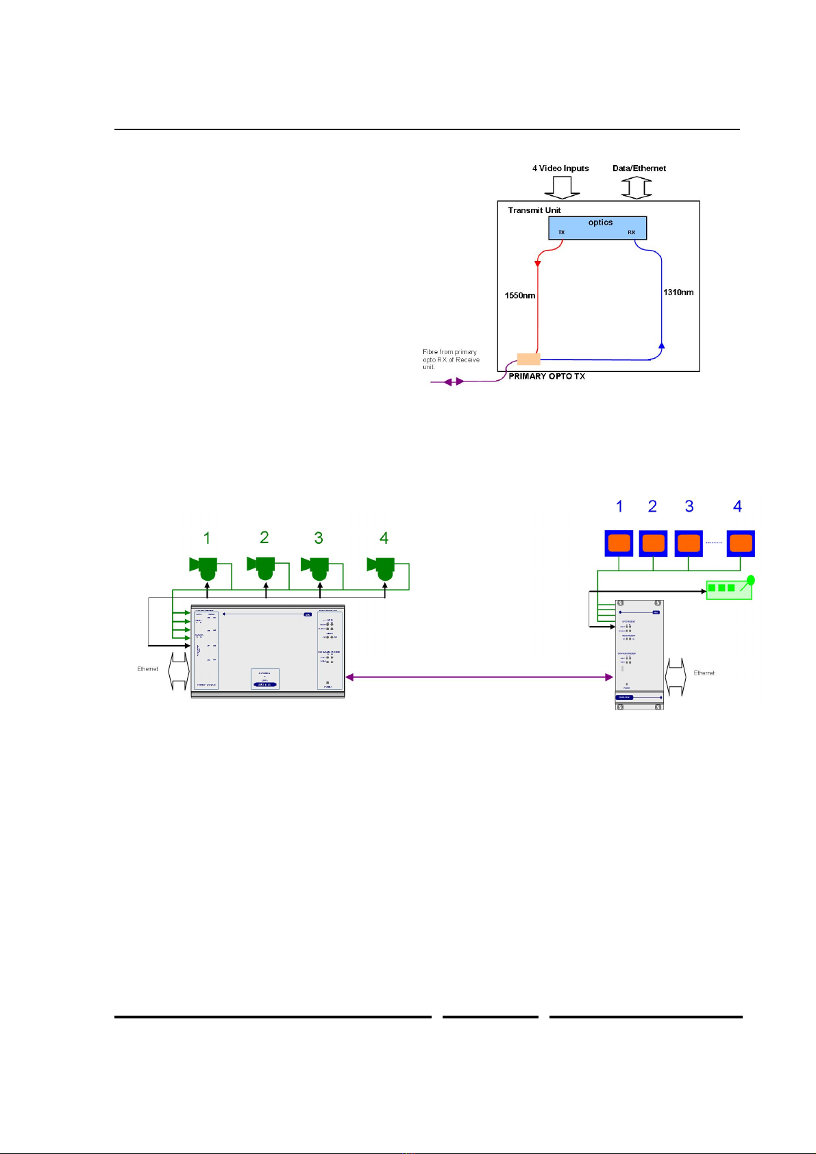
Unit Functional Schematic
................................
................................
................................
..................
3
Optical Connection
................................
................................
................................
.............................
3
Connections
4
Video Input Connections
................................
................................
................................
....................
4
Optical Connections
................................
................................
................................
...........................
4
Power Connection
................................
................................
................................
..............................
4
Ethernet Connection
................................
................................
................................
...........................
4
Data and Audio Channel Connections
................................
................................
...............................
4
Data and Audio Channel Configuration
5
Data and Audio Channel Configuration
................................
................................
..............................
5
Data Interface Connections Channel A
................................
................................
..............................
5
Data Channel A Configuration
................................
................................
................................
............
5
Data / Audio Channel B Configuration
................................
................................
...............................
6
Data Interface Daughter Board
Options
................................
................................
.............................
6
Audio / Data Interface Connections RJ45
-
Channel B
................................
................................
......
6
Front Panel Indicators
7
Power LED
................................
................................
................................
................................
..........
7
Video Input LED’s
................................
................................
................................
...............................
7
Fibre Optic LED’s
................................
................................
................................
...............................
7
Low Speed Data LEDs
................................
................................
................................
.......................
7
Ethernet Operation
9
Physical Information
10
Dimensions
................................
................................
................................
................................
.......
10
Mounting Details
................................
................................
................................
...............................
10
Removal / replacement from / to the Case
................................
................................
.......................
10
Safety
10
Maintenance and Repair
10

AMG Systems Ltd. reserves the right to make changes to this
document without notice. The information herein is believed to
be acc
urate. No responsibility is assumed by AMG for its use.
Page
3
of
12
AMG4743BxE
-
SF
Instruction
Sheet
D18215
-
01.doc
Introduction
Unit Fun
ctional Schematic
The
AMG4743BxE
-
SF
transmits up to 4
video and 2 data signals to the
AMG4744BxEN
-
SF
.
It also receives 2 data signals transmitted
from the
AMG4744BxEN
-
SF
.
Ethernet connectivity is also provided
between the two units.
Optical Connecti
on
The
AMG4743BxE
-
SF
is connected as illustrated below when used with an
AMG4744BxERN
-
SF
rackmount receive unit acting as a point to point system.

AMG Systems Ltd. reserves the right to make
changes to this
document without notice. The information herein is believed to
be accurate. No responsibility is assumed by AMG for its use.
Page
4
of
12
AMG4743BxE
-
SF
Instruction
Sheet
D18215
-
01.doc
Connections
Video Input Connections
No. of channels
................................
....
4
Connector
................................
............
75 ohm BNC Socket.
Input Impedance
................................
..
75 o
hm terminated.
Input Level
................................
...........
1 volt p
-
p nominal
Frequency Response
...........................
10Hz to 7MHz.
Optical Connections
PRIMARY OPTO OUT
Connector
................................
............
LC/PC
Optical Fibre
................................
........
One fibre
-
Singlemode
Primary Optical Launch Power
............
-
5dBm
Wavelength
................................
..........
1510nm
Primary Optical Sensitivity
...................
-
22dBm
Wavelength
................................
..........
1310nm
Power Connection
Connector Type
................................
...
2.1mm screw lock long power jack
–
centre positive
Connector Partno.
................................
Switchcraft S761K, AMG G16125
-
00
Supply Voltage
................................
.....
13.5 to 18.0 Volts DC.
Maximum Power
................................
.
10 Watts
Ethernet Connection
Ethernet D
ata Connector
....................
RJ45
Interface
................................
...............
Auto
-
negotiation up to 100BASE
-
TX full duplex
Ethernet Data Rate
..............................
Maximum 50Mbits/s total Ethernet traffic on fibre
Data and Audio Channel Connections
Total No. of Data Channels
.................
2 channels
DATA CHANNEL A
Data Connector
................................
....
RJ45
Channel A Interface
.............................
On Board Data Interface
–
RS232, RS422 or RS485. Selected
by slide switch above the RJ45 connector.
RS232
–
switch position
-
high (closest to BNC connections)
RS422
–
switch position
–
middle
RS485
–
switch position
–
low (furthest
from BNC connections)
DATA CHANNEL B
Data Connector
................................
....
RJ45
Channel B Interface
.............................
Defined by data/audio interface daughter board fitted into Slot 1
on main board and indicated by the 'x' in the AMG partno.

AMG Systems Ltd. reserves the right to make changes to this
document without notice. The information herein is believed to
be accurate. No responsibility is assumed by AMG for its use.
Page
5
of
12
AMG4743BxE
-
SF
Instruction
Sheet
D18215
-
01.doc
Data and Audio Channel Configuration
Data and Au
dio Channel Configuration
The
AMG4743BxE
-
SF
and rackmount equivalent
AMG4743BxER
-
SF
sends and receives data
to/from Channel A and Channel B. Channel A is a single data interface selectable by the user with the
slide switch on the rear panel. Channel B carr
ies a second channel of data / audio, the function and
physical interface being determined by the type of daughter board fitted to the B Channel data slot.
Data Interface Connections Channel A
Channel A
RJ45 Pin
No.
RS485
[switch low]
RS422 [switch
mid]
RS232
[switch high]
Cat 5/6 Cable
Colour Code T568B
1
IN + (A)
GND
White/orange
2
IN
-
(B)
IN
Orange
3
White/green
4
Blue
5
White/blue
6
Green
7
IN/OUT + (A)
OUT + (A)
N/A
White/brown
8
IN/OUT
-
(B)
OUT
-
(B)
OUT
Brown
Note: (A) or (B) in brackets in above table refers to RS485 / RS422 data specification, not Channel A,
Channel B.
Data Channel A Configuration
Channel A is always present and allows for a RS232, RS422 (full duplex, four wire) or RS
485 (half
duplex, two wire) interface depending on the position of the switch located above the RJ45 connector.
The switch signifies the presence of the X16004 Low Speed Data/Audio Interface Board. If there are
LED's present on the RJ45 connector then an X
16003 Ethernet Interface Board is fitted.
The data input for both the RS485 and the RS422 modes detects a tri
-
state input condition by
monitoring the differential voltage level across the input. A differential level below 600mV positive or
negative will b
e detected as a tri
-
state condition. A level above 600mV positive or negative will be
detected as a logic 1 or logic zero respectively. It is important therefore to terminate the RS485 bus or
the RS422 input bus using 120Ωif a pre
-
bias is present on the R
S485 or RS422 bus.
A large number of third party equipment manufacturers apply a pre
-
bias on their RS485 bus. This pre
-
bias is applied by pulling one arm of the RS485 bus high (+5 volts) and the other arm low (0 volts)
using high value resistors within t
he third party equipment. In order to ensure that the AMG equipment
detects a tri
-
state condition, then these resistors should have a value above 5kΩ. If the third party
bias resistors are less the 750Ωthe bus can be double or triple terminated as requir
ed to ensure that a
tri
-
state level is detected.
Note: The Data Channel A is shipped from the factory set up for RS485 operation unless otherwise
requested.

AMG Systems Ltd. reserves the right to make changes to this
document without notice. The information herein is believed to
be accurate. No responsibility is assumed by AMG for its use.
Page
6
of
12
AMG4743BxE
-
SF
Instruction
Sheet
D18215
-
01.doc
Data / Audio Channel B Configuration
Data Channel B is operational when fitted with the appropri
ate daughter board.
Data Interface Daughter Board Options
The data interface daughter board options are as follows:
Option Code
'x'
Part No.
Description
0
X12542
4 Wire Audio Interface Daughter Board
1
X04057
RS422/485 Data Interface Daughter Board
2
X04049
RS232 Data Interface Daughter Board
3
X04058
20mA Current Loop Data Interface Daughter Board
4
X12579
TTL Data Interface Daughter Board
5
X12578
Contact Closure Data Interface Daughter Board
6
X13038
FTT10A Echelon Lonworks Data Interface Daugh
ter Board
Audio / Data Interface Connections RJ45
-
Channel B
RJ45 Channel B low speed data/audio interface connections:
Channel B
RJ45 Pin
No.
Data / Audio
Daughter Board
Cat 5/6 Cable
Colour Code T568B
1
White/orange
2
Orange
3
OUT + (A)
White/green
4
IN
-
(B)
Blue
5
IN + (A)
White/blue
6
OUT
-
(B)
Green
7
White/brown
8
Brown
Note: (A) or (B) in brackets in above table refers to RS485 / RS422 data specification, not Channel A,
Channel B.

AMG Systems Ltd. reserves the right to make changes to this
document without notice. The information herein is believed to
be accu
rate. No responsibility is assumed by AMG for its use.
Page
7
of
12
AMG4743BxE
-
SF
Instruction
Sheet
D18215
-
01.doc
Front Panel Indicators
Power LED
Power
................................
..................
G
reen
-
unit powered
Off
-
no power applied to unit
Video Input LED’s
Video Present CH1
-
4
..........................
Green
-
video signal present on input BNC
R/G
-
channel present but no video on I/P BNC
Fibre Optic LED’s
Primary Opto Sync TX
.........................
Green
-
optical channel transmit
ting
Off
-
optical channel not transmitting
Primary Opto Sync RX
........................
Green
-
optical channel receiving
Org
-
optical channel receiving but not sync.
Off
-
optical channel not transmitting
Low Speed Data LEDs
Channel A
Data Present TX (RS485 or RS422)
...
Green
-
logic zero (+V,
-
V) present on IN+, IN
-
Red
-
logic one (
-
V,V+) present on IN+, IN
-
Off
-
tri
-
state off or no connection on IN+, IN
-
Data Present TX (RS232)
...................
Green
-
logic zero (+V) present on input IN+
Red
-
logic transitions present on input
IN+
Off
-
logic one (
-
V) present on input IN+
This represents the data signals being transmitted on the optical fibre
Data Present RX (RS485 or RS422)
...
Green
-
logic zero (+V,
-
V) present on OUT+, OUT
-
Red
-
logic one (
-
V,+V) present on OUT+, OUT
-
Of
f
-
tri
-
state off or no connection on OUT+, OUT
-
Data Present RX (RS232)
...................
Green
-
logic zero (+V) present on OUT+
Red
-
logic transitions present on OUT+
Off
-
logic one (
-
V) present on OUT+
This represents the data signals being received on the optic
al fibre
Channel B
(When RS232 data daughter board fitted)
Data Present TX
................................
..
Green
-
logic zero (+V) present on IN+
Red
-
logic transitions present on IN+
Off
-
logic one (
-
V) present on IN+
This represents the data signals being transmitted on the opt
ical fibre
Data Present RX
................................
..
Green
-
logic zero (+V) present on OUT+
Red
-
logic transitions present on OUT+
Off
-
logic one (
-
V) present on OUT+
This represents the data signals being received on the optical fibre

AMG Systems Ltd. reserves the right to make changes to this
document without notice. The information herein is believed to
be accu
rate. No responsibility is assumed by AMG for its use.
Page
8
of
12
AMG4743BxE
-
SF
Instruction
Sheet
D18215
-
01.doc
Channel B
(When RS485 / RS422 data da
ughter board fitted)
Data Present TX
................................
..
Green
-
logic zero (+V,
-
V) present on IN+, IN
-
Red
-
logic transitions present on IN+, IN
-
Off
-
logic one (
-
V, +V) present on IN+, IN
-
This represents the data signals being transmitted on the optical fibre
Data P
resent RX
................................
..
Green
-
logic zero (+V,
-
V) present on OUT+, OUT
-
Red
-
logic transitions present on OUT+, OUT
-
Off
-
logic one (
-
V , +V) present on OUT+, OUT
-
This represents the data signals being received on the optical fibre
Channel B
(When audio daught
er board fitted)
Audio Present TX
................................
.
Green
-
audio present >
-
40dBm
Red
-
audio present > 0dBm (overload at +6dBm)
Off
-
audio not present or <
-
40dBm
This represents the audio signals being transmitted on the optical fibre
Audio Present RX
................................
Green
-
audio
present >
-
40dBm
Red
-
audio present > 0dBm (overload at +6dBm)
Off
-
audio not present or <
-
40dBm
This represents the audio signals being received from the optical fibre.

AMG Systems Ltd. reserves the right to make c
hanges to this
document without notice. The information herein is believed to
be accurate. No responsibility is assumed by AMG for its use.
Page
9
of
12
AMG4743BxE
-
SF
Instruction
Sheet
D18215
-
01.doc
Ethernet Operation
In order for the AMG system to transmit Ethernet signals,
an onboard RJ45 Ethernet interface or
X16003 Ethernet interface adaptor should be fitted to both the Transmit unit and the Receive unit.
The Ethernet interface can operate at either 10Mbits/s half duplex, or 100Mbit/s full duplex, and data is
transmitted
from one port the other port with the minimum of delay or buffering. The maximum
bandwidth (at 100Mbit/s full duplex) available for transmission across the fibre link is nominally
50MBit/s.
The 100BaseT port does not implement MDI/MDIX; it should be con
nected with a straight though
cable to an external switch port and with a cross over cable when connected directly to a PC or DTE.

AMG Systems Ltd. reserves the right to make changes to this
document without notice. The information herein is believed to
be accurate. No responsibility is assumed by AMG for its use.
Page
10
of
12
AMG4743BxE
-
SF
Instruction
Sheet
D18215
-
01.doc
Physical Information
Dimensions
Height
................................
...................
112mm
Width
................................
....................
170mm (excluding connectors)
Depth
................................
...................
70mm
Weight
................................
..................
1000grams
Mounting Det
ails
The AMG unit is supplied with a clip
-
on mounting bracket which should be attached to a panel or wall
using 2 off 4.0mm screws, see diagram on page 1 for dimensions. The unit is clipped into the
mounting bracket, and is then held firmly in position.
Removal / replacement from / to the Case
Note:
-
The AMG unit PCB's are static sensitive. Handle with proper care and use normal electrostatic
discharge (ESD) procedures. Use properly grounded protection (for example, wrist straps) when
handling the PCB.
To remove units from the case to access the data expansion boards and the daughter boards, remove
the 2 or 4 fixing screws on the rear panel and slide the PCB's out of the case.
Ensure that the fibres do not snag or get trapped.
To replace the PCB's in
to the case, slide the PCB's gently into the case aligning the boards with the
appropriate slots. Ensure that the fibre do not snag or get trapped.
Safety
AMG Optical Fibre Products use Class 1 laser systems in accordance with EN 60825
-
2:2000.
It is al
ways advisable to follow good practice when working with optical fibre systems. This includes:
Do not stare with unprotected eyes or with any unapproved collimating device at fibre
ends or connector faces, or point them at other people.
Use only approved
filtered or attenuating viewing aids
For other safety issues and advice on good practice associated with optical fibre systems, please see
EN 60825
-
2:2000 or your local safety officer.
Maintenance and Repair
There are no user serviceable parts within A
MG products. See unit data sheet for full specification.
In case of problem or failure, please call your local support centre or contact:
AMG Systems Ltd.
at
3 The Omega Centre, Stratton Business Park, Biggleswade, Beds., SG18 8QB, UK.
Phone
+44 (0
) 1767 600 777
Technical Support
+44 (0) 1767 604 491
Email
techsupport@amgsystems.com

AMG Systems Ltd. reserves the right to make changes to this
document without notice. The information herein is believed to
be accurate. No responsibility is assumed by AMG for its use.
Page
11
of
12
AMG4743BxE
-
SF
Instruction
Sheet
D18215
-
01.
doc
This page is intentionally blank.

AMG Systems Ltd. reserves the right to make changes to this
document without notice. The information herein is believed to
be accurate. No responsibility is assumed by AM
G for its use.
Page
12
of
12
AMG4743BxE
-
SF
Instruction
Sheet
D18215
-
01.doc
This page is intentionally blank.
This manual suits for next models
1
Table of contents
Other AMG Extender manuals