AMGO MR06 Manual

Portable Mid-rised Lift
Model:MR06

1
CONTENTS
Product Features and Specifications ......................................................... 1
Installation Requirement..…………………………...…..…….………………………………………….2
Steps of Installation...………………..................…………………............................. 3
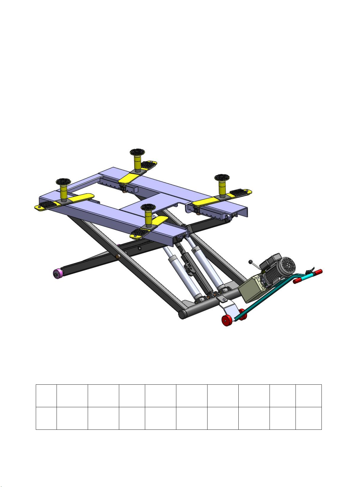
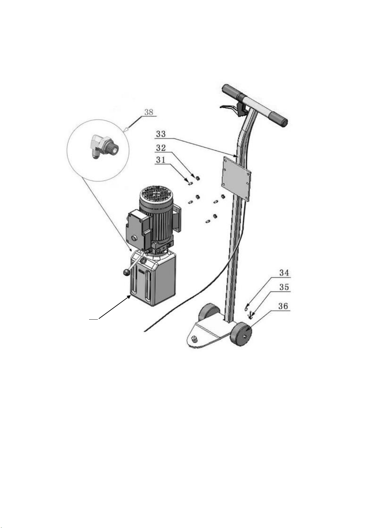
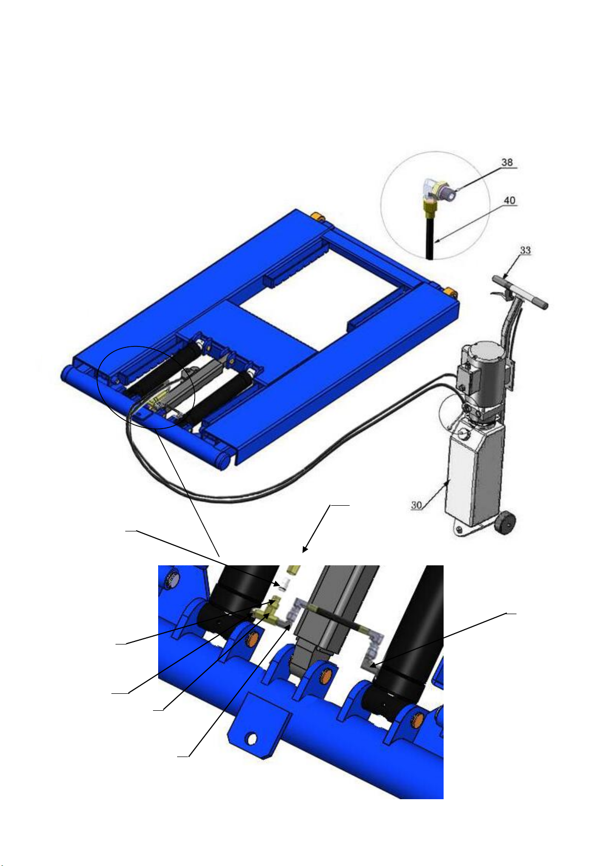
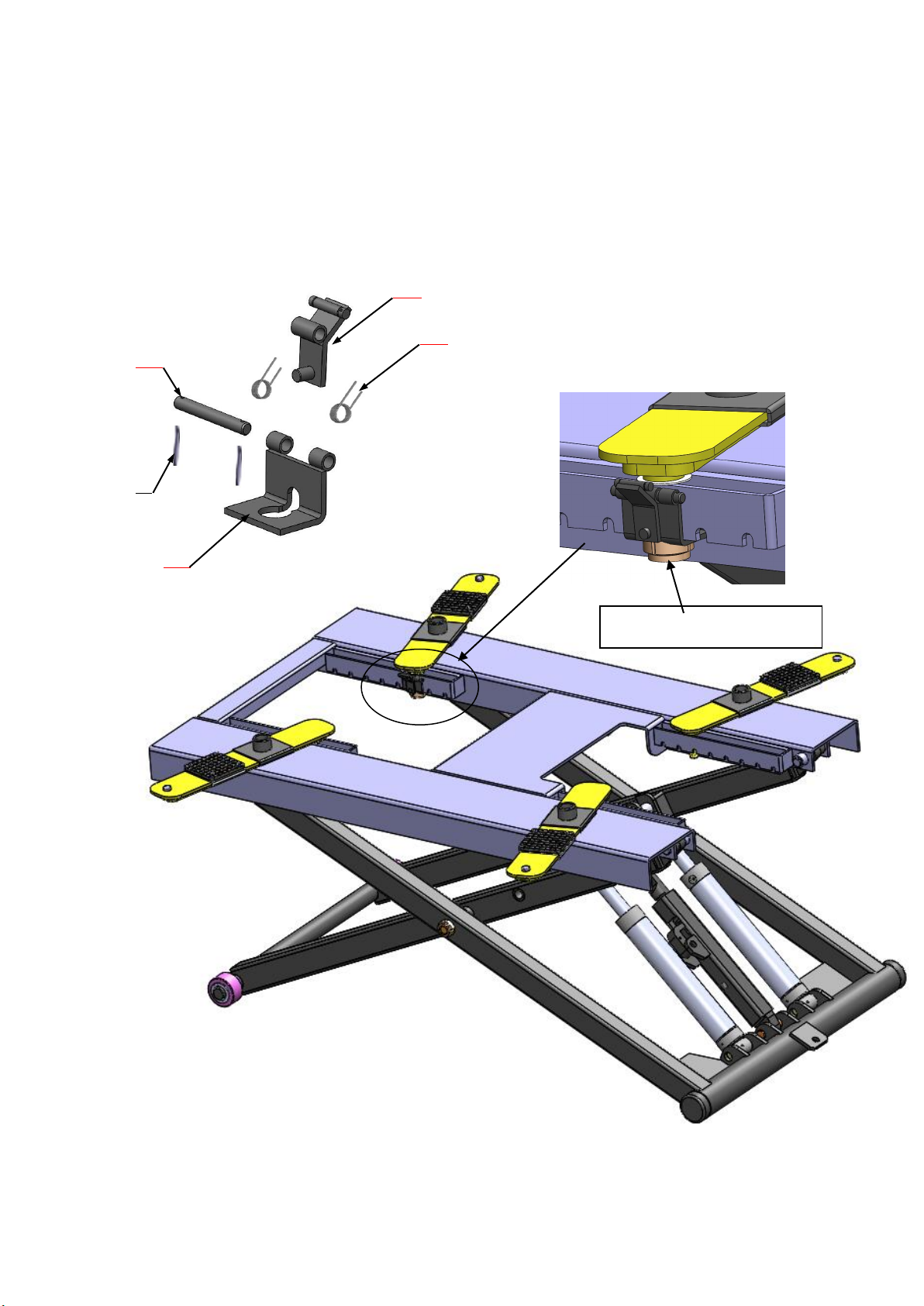
Exploded View...……………………………..………….…...….………………………………………….. 9
Operation Instruction..……………………………………..…..…………………………………………..12
Maintenance …………………………………………………………………………………………………….. 13
Trouble Shooting ...……………………………………….....…………………………………………….. 14
MR06 Parts List ...……………………………………………..….…………………………………………. 15

1
I. PRODUCT FEATURES AND SPECIFICATIONS
PORTABLE MID-RISED MODEL MR06
●Manual safety lock: 7 position safety locks, mechanical safety locks release, No need
air source.
●High speed: From 0-1090mm (43”) in just 21 seconds
●Portable design: It is easy to move the whole lift with the power unit stand
●Adjustable rubber pad included
Fig.1
MODEL MR06 SPECIFICATIONS
Model Lifting
Capacity
Raised
Height
Lifting
Time
Overall
Length
Platform
Width
Swing
Width
Lowered
Height
Gross
Weight Motor
MR06 2.8T
6,000 lbs
1090mm
43” 21S 1885mm
74-1/4”
1000mm
39-3/8”
1604mm
63 1/8”
125mm
5”
394Kg
840 lbs 1.5HP

2
II. INSTALLATION REQUIREMENT
A. TOOLS REQUIRED
Screw Set
English Spanner (12″)
Wrench sets:(13#、15#、17#、19#)
B. POWER SUPPLY
The electrical source must be 1.5HP minimum. The source cable size must be
2.5mm² and in good condition of contacting with floor.
Fig. 2
Pliers
Grease gun
Hook spanner (40~42mm)

3
III. INSTALLATION STEPS
A. Check the parts before assembly, make sure all the parts are completed.
1. Packaged lift, Parts box, Power Unit and Power Unit Stand.
Move the parts aside, open the outer packing and check the parts according to the
shipment parts list (See Fig. 3).
2. Open the parts box, check the parts according to the part list (See Fig. 4).
Fig. 3
Fig. 4
41

4
3. Check the parts of the parts bag according to the parts bag list (See Fig. 5).
B. Install brake handle (See Fig. 6)
Fig.5
Fig.6
Firstly,dismantle handle grip,then
put brake handle in and tighten
screw

5
Install power unit and power unit fitting (See Fig. 7)
Fig. 7
30

6
C. Install oil hose (See Fig.8)
Caution: Wrap some PTFE TAPE
when install fitting
43
37A
42
37B
39
27
29
Fig.8

7
D.Install safety cable
1. Insert the Safety cable to the hole
of the bolt of M8*16.(See Fig.9)
2. Lower the lift in order to lock it on the safety device then tighten the bolt to tighten
the safety cable.
②
①
Fig.9
Fig.10

8
E.Tighten supporting arm
1. Raise the lift up to 39-3/8”and lock the safety device, then tighten the self-lock
nut .(See Fig. 11)
Fig. 11
Tighten the self-lock nut
19A
19D
19B
19C
24

9
F Install electric system
Connect the power source on the data plate of Motor
Note: 1. For the safety of operators, the power wiring must contact the floor well.
2. Pay attention to the direction of rotations when using three phase motors.
Single phase motor (See Fig. 12)
1. Connecting the two power supply lines (fire wire Land zero wire N) to terminals of AC
contactor marked L1, L2 respectively.
2. Connecting the two motor wires to terminals of AC contactor marked T1, T2.
3. Connecting L2 to A2 of AC contactor.
4. Two wires of control button connected with terminals of AC contactor marked A1, L1.
Fig. 12
Single phase
Circuit diagram

10
IV. EXPLODED VIEW
Model MR06
Fig. 13
9A 19
18
4445
46
47

11
CYLINDER
MANUAL POWER UNIT
220V/60HZ/1 phase
Fig.14
Fig.15

12
Illustration of hydraulic valves
Single phase 110 V ,60 HZ Manual power unit(Fig.16)
V. OPERATION INSTRUCTIONS
1. Install the oil hose between oil cylinder and power unit, connect with the power
supply wire well. The machine can be ready to use.
2. When lifting vehicle, be sure the center of gravity of vehicle must be in the middle
of lift, select the suitable adapters and move the arms to find the support point.
(See Fig.17,18)Make sure the safety lock must be in engaged when lifting (See
Fig. 19).
3. Lower the lift: Press the button “UP”, until the safety lock is in released position
clench the brake handle(See Fig.20,21), lower the lift by pushing lowering handle.
Fig. 17 Fig.18
Fig.16
Relief valve
Throttle valve
Release valve
Oil outlet
Oil return port
Pull cable to move supporting arm Relax cable to fasten supporting arm
Check valve
Handle for
release valve

13
4. Move the lift with the trailer assembly(See Fig. 22)
VI. MAINTENANCE SCHEDULE
Monthly:
1. Lubricate all moving parts with lubricant (See Fig.23).
Fig. 23
Fig. 22
Fig.19
Fig.20
Fig.21
Clench the brake
handle to release
Safety engaged
Safety released
Towing trailing

14
2. Check all connectors, bolts and pins to insure proper mounting.
3. Make a visual inspection of all hydraulic hoses/lines for possible wear or leakage.
Every six months:
1. Make a visual inspection of all moving parts for possible wear, interference or
damage.
2. Check all fastener and re-torque.
VII. TROUBLE SHOOTING
TROUBLE CAUSE REMEDY
Motor does not
run
1. Button does not work
2. Wiring connections are not in good
condition
3. Motor burned out
4. Safety Switch is damaged
5. AC contactor burned out
1. Replace button
2. Repair all wiring connections
3. Repair or replace motor
4. Replace the Safety Switch
5. Replace AC Contactor
Motor runs but
the lift is not
raised
1. Motor runs in reverse rotation
2. Gear Pump out of operation
3. Release Valve in damage
4. Relief Valve or Check Valve in damage
5. Low oil level
6. Overload lifting or low pressure
1.Reverse two power wire
2. Repair or replace
3. Repair or replace
4. Repair or replace
5. Fill tank
6.Check load or adjust the
pressure
Lift does not
stay up
1. Release Valve out of work
2. Relief Valve or Check Valve leakage
3. Cylinder or Fittings leaks
Repair or replace
Lift raises slowly
1. Oil line is jammed
2. Motor running on low voltage
3. Oil mixed with air
4. Gear Pump leaks
5. Overload lifting
1. Clean the oil line
2. Check Electrical System
3. Fill tank
4. Repair or replace
5. Check load

15
Lift cannot lower
1. Safety device are in activated
2. Release Valve in damage
3. Oil system is jammed
1. Release the safeties
2. Repair or replace
3. Clean the oil system
VIII. PARTS LIST FOR MODEL MR06
Item Part# Description QTY. Note
1 11640001 Platform 1
2 11640002A Stackable Adapter Bracket 4
3 11209052B Stackable Adapter (2.5”) 4
3A 11209051B Stackable Adapter (1.5”) 4
4 10201046A Rubber Pad Assy. 4
4A 10420138 Socket bolt 4
4B 10209134 Rubber pad 4
4C 11680030C Rubber Pad Frame 4
5 10209009 Cup Head Bolt 16
6 10680004 Rubber Pad 4
7 10640003 Supporting pad 4
8 11640023A Limit pin 4
9 11640004 Supporting arm 4
10 10640005 Washer 10
11 10640109 Washer 4
11A 10620022 Self locking Nut 8
12 10640116 Cylinder 2
13 10206032 Snap Ring 12
14 11640057 Pin For Cylinder Connecting 2
14A 11640012 Pin 2
15 11640006A Pin for Cylinder 2
16 11640017B
Outer Scissor
1
17 11640009 Inner Scissor Pin 2
18 11640130 Safety Bar Set 2
19 19A 11640134 Slide limit block 4
19B 11640135 Slide stop 4

16
19C 11640136 Safety Pin 4
19D 10640127 Spring 8
20 10203004A Bronze Bush 8
21 10420023A Washer 2
22 10420132A Bronze Bush 4
23 11640022 Roller 2
24 10630107 Split Pin 10
25 11640016B Inner Scissor 1
26 10610003A Slider 2
27 1061K107 Straight Fitting 1
28 10640114 Oil Hose 1
Item Part# Description QTY.
Note
29 10420097 Straight Fitting 2
30 81513006/
81513007
Manual Power Unit 1
31 10209003 Hex Bolt 4
32 10209005 Self locking Nut 4
33 10640138 Power Unit Stand 1
34 10206006 Washer 2
35 10201005 Split Pin 2
36 10640023 Roller 2
37A 10201020 900Fitting 1
37B 10209119 compensation valve 1
38 10209060 Straight Fitting For Power Unit 1
39 10206062 T Fitting 1
40 10630110 Oil Hose 1
41 10640500A Parts Box 1
42 10420244 Straight fitting 1
43 10420245 Straight fitting 1
44 11640132 Safety block 1
45 11640131 Safety block pin 1
46 11640675 Self-lock supporting tube 1
47 11640667 Self-lock supporting pin 1
48 10640115 Brake Handle 1
PARTS FOR HYDRAULIC CYLINDER
12-1 11640657 Bore Weldment 2
12-2 11640031A Piston Rod 2
12-3 10201034 Bleeding Plug 2

17
12-4 11203083 Head Cap 2
12-5 10209078 Dust Ring 2
12-6 10201032 O - Ring 2
12-7 10203084 O - Ring 2
12-8 11203079 Piston 2
12-9 10206069 O-Ring 2
12-10 10203082 O-Ring 2
12-11 10410087 Y-Ring 2
12-12 10410086 Support Ring 2
12-13 10206071 Nut 2
12-14 10620064 Greasing Fitting 4
Manual Power Unit 110V/60HZ/1 phase
Item
Part#
Description
QTY.
Item
Part#
Description
QTY
1 81400180 Rubber pad 2 22 41030055 Ac contactor 1
2 81400073 Start capacitor 1 23 81400287 Cover of motor
1
3 10420148 Cup Head Bolt with
washer 6 24 71111106 AMGO power unit label
1
4
81400066
Cover of capacitor
2
25
81400296
Nut
1
5 81400363 Motor connecting
shaft 1 26 81400459 Throttle valve body 1
6
81400362
Manifold block
1
27
10209069
O-ring
1
7 10209149 Washerφ64 28 81400266 Relief valve 1
8 81400276 Iron plug 1 29 81400284 Iron plug 1
9 81400259 Red rubber plug 1 30 81400452 Hair pin 1
10 85090142 Lock Washer 4 31 81400451 Handle for release
valve 1
11 81400312 Gear pump 1 32 10209020 Plastic ball for arm
lock bar 1
12 81400294 Buffer valve 1 33 81400125 Nut for release valve
1
13 10209034 Washer φ82 34 81400124 Shim for release
valve 1
14
81400295
Socket bolt
2
35
81400449
Valve seat(low)
1
15 81400365 O-ring 1 36 070001 Release valve 1
16 10209152 Ties 1 37 070002 Check valve 1
17 85090167 Magnet 1 38 81400375 Oil suction pipe 1
18 81400290 Filter 1 39 81400376 Oil return pipe 1
19
81400412 Steel plate motor 1
40
81400364
Hose
clamps(stainless
steel )
1
20 81400086 Run capacitor 1 41 81400263 Filler cap 1
21 10420070 Button switch 1 42 81400320
Reservoir 1

18
72126710
10/2018
Other manuals for MR06
1
Table of contents
Other AMGO Scissor Lift manuals
Popular Scissor Lift manuals by other brands

Terex
Terex Genie GS-2669 DC Service and repair manual

LGMG
LGMG SC0407E Maintenance manual

AUTEC
AUTEC ASLP-3005 user manual

Custom Equipment
Custom Equipment Hy-Brid HB 1030E Operation, safety and maintenance manual

JLG
JLG 3369LE Operation and safety manual

POP UP
POP UP PUSH 6 PRO Operator's Safety and Maintenance Handbook