AMI 227 User manual

10500 Orbital Way
Pacoima, California 91331 U.S.A.
MODEL 227 POWER SUPPLY
OPERATION MANUAL
Document No. 740063

MODEL 227
OPERATION MANUAL
Doc # 740063 Rev E
NOTICE
This document and the information contained herein is the property of Arc Machines, Inc.. It
is proprietary and submitted and received in confidence. It shall be used only for the purpose
for which it is submitted and shall not be copied in whole or in part without the prior express
written permission of Arc Machines, Inc.
The information in this document has been carefully reviewed and is believed to be accurate.
However, no responsibility is assumed for inaccuracies.
Information and instructions in this document are subject to change and Arc Machines, Inc.
reserves the right to change specifications and data without notice.
WARNING
The nature of the GTAW process creates some POTENTIAL HAZARDS. In accordance
with international safety regulations the EXCLAMATION SYMBOL indicates that this
equipment is considered HAZARDOUS until an operator has been made aware of these
POTENTIAL HAZARDS by READING THIS MANUAL. The LIGHTNING FLASH
SYMBOL indicates that there are potential electrical hazards. The use and display of these
symbols make it the OPERATOR’S RESPONSIBILITY TO INSURE THAT HE HAS
READ AND/OR BEEN MADE AWARE OF ALL OF THE SAFETY-RELATED ITEMS
CONTAINED IN THIS MANUAL.
Publication date : First Edition - February 12, 1992
Copyright 1992 by Arc Machines, Inc.
All rights reserved
REV
DCO # CHANGE DESCRIPTION
DATE
APR
A
2367
Revised to include required IEC-974 information 10/03/96 GPE
B
3053
Add M227/207-CW Spec-info pgs: iv, v, 1.1, 2.4, 4.14,
4.16, 5.7, 7.6, 7.8, 8.1, 8.2. 04/08/98 GPE
C
3583
Added Offset adj. Information to sect. 7. Replaced Sect. 7,
Pg. i & iv.
03/23/00 GPE
D 3682 Removed ref to miller coolant pages 8.1,8.2 7/19/00 GPE
E 4633 Correct typo in section 7.2.14 2/25/08 LEC
i

MODEL 227
OPERATION MANUAL
Doc # 740063 Rev E
EFFECTIVITY
Features and operation of the Model 227 are derived mostly from SOFTWARE. This
document is based on the latest STANDARD version of SOFTWARE at the time of last
revision (see revision page).
Some deviations in actual operation, from this document, are possible depending on the
software version of a particular machine. Please feel free to contact Arc Machines
Service Department for documentation or information on how software updates effect
this document.
ii

MODEL 227
OPERATION MANUAL
Doc # 740063 Rev E
TABLE OF CONTENTS
SECTION DESCRIPTION PAGE
SECTION I INTRODUCTION
1.0 Introduction 1.1
1.1 Safety Precautions 1.2
1.2 Operational Precautions 1.4
1.3 RF and EMI emissions 1.5
1.4 Shock Hazard Warning 1.8
SECTION II SPECIFICATIONS
2.0 Electrical 2.1
2.1 Physical Construction 2.3
2.2 Programmable Functions 2.3
2.3 Multi-level Functions 2.4
2.4 Non-Programmable Functions 2.4
2.5 Ambient Temperature Ranges 2.4
2.6 Cable Operating Distance Limits 2.4
SECTION III INSTALLATION
3.0 Inspection 3.1
3.1 Power Connection 3.1
3.2 Welding Gas Connections 3.2
3.3 Adapter Cable to M-227 Installation 3.3
3.4 Weld Head Installation 3.7
3.5 Ground (Work) Cable Installation 3.7
3.6 Remote Pendant Installation 3.8
SECTION IV SYSTEM FUNCTIONS
4.0 Introduction 4.1
4.1 Functional Description, General 4.1
4.2 Weld Library and Description 4.3
4.3 Weld Sequence 4.3
4.4 Panel Keys 4.11
4.5 Operate Mode Switch 4.14
4.6 Faults 4.14
4.7 Sensor 1,2,3 Faults 4.16
4.8 Set-Up Functions 4.16
4.9 Glossary of Abbreviations 4.17
4.10 Glossary of Terms 4.18
iii

MODEL 227
OPERATION MANUAL
Doc # 740063 Rev E
TABLE OF CONTENTS
SECTION DESCRIPTION PAGE
SECTION V OPERATION
5.0 Introduction 5.1
5.1 Initial Power-On 5.1
5.2 Use of Next/Prev 5.2
5.3 Weld Schedule Selection 5.3
5.4 Pass Advance 5.4
5.5 Viewing Function Values 5.6
5.6 Overriding Function Values 5.6
5.7 Set Up Functions 5.7
5.8 Remote Pendant Operation 5.11
5.9 Rotation Calibration 5.14
5.10 Wire Feed Calibration 5.15
5.11 Manual Advance Function 5.16
5.12 Welding Operation 5.17
5.13 Printer Operation 5.18
SECTION VI PROGRAMMING
6.0 Introduction 6.1
6.1 Create a Weld Schedule 6.1
6.2 Modify a Weld Schedule 6.4
6.3 Copy a Weld Schedule 6.5
6.4 Transfer/Receive a Weld Schedule 6.5
6.5 Delete a Weld Schedule 6.6
6.6 Program Select Function 6.6
SECTION VII CALIBRATION
7.0 Introduction 7.1
7.1 Equipment Required 7.1
7.2 Current Servo 7.2
7.3 AVC Servo 7.4
7.4 Oscillator Servo 7.5
7.5 General Maintenance 7.7
7.6 System Fault Corrections 7.8
7.7 Error Messages 7.11
7.8 Miscellaneous Maintenance 7.12
SECTION VIII OPTIONS
8.0 Introduction 8.1
8.1 M227/207-CW & M207-CW Cooling Units 8.1
8.2 M-227-EMM External Memory Module 8.3
iv

MODEL 227
OPERATION MANUAL
Doc # 740063 Rev E
LIST OF ILLUSTRATIONS
NUMBER DESCRIPTION PAGE
FIGURE 1 SYSTEM CONFIGURATION 1.7
FIGURE 2 INSTALLATION LOCATIONS 3.4
FIGURE 3 AC POWER SET-UP 3.5
FIGURE 4 CABLE CONNECTIONS 3.6
FIGURE 5 SEQUENCE TIMING CHART 4.7
FIGURE 6 PANEL KEY LOCATIONS 4.8
FIGURE 7 USE OF NEXT/PREV KEYS 5.5
FIGURE 8 STANDARD REMOTE PENDANT 5.10
FIGURE 9 M227/207-CW or M207-CW INSTALLATION 8.4
v

MODEL 227
OPERATION MANUAL
Doc # 740063 Rev E
SECTION I - INTRODUCTION
1.0 INTRODUCTION
This manual is intended to assist users of this equipment in set-up and basic
operation. Automated welding requires a good deal of operator expertise which
also requires AMI supplied, hands-on training. THIS MANUAL IS NOT
INTENDED AS A SUBSTITUTE FOR THAT TRAINING.
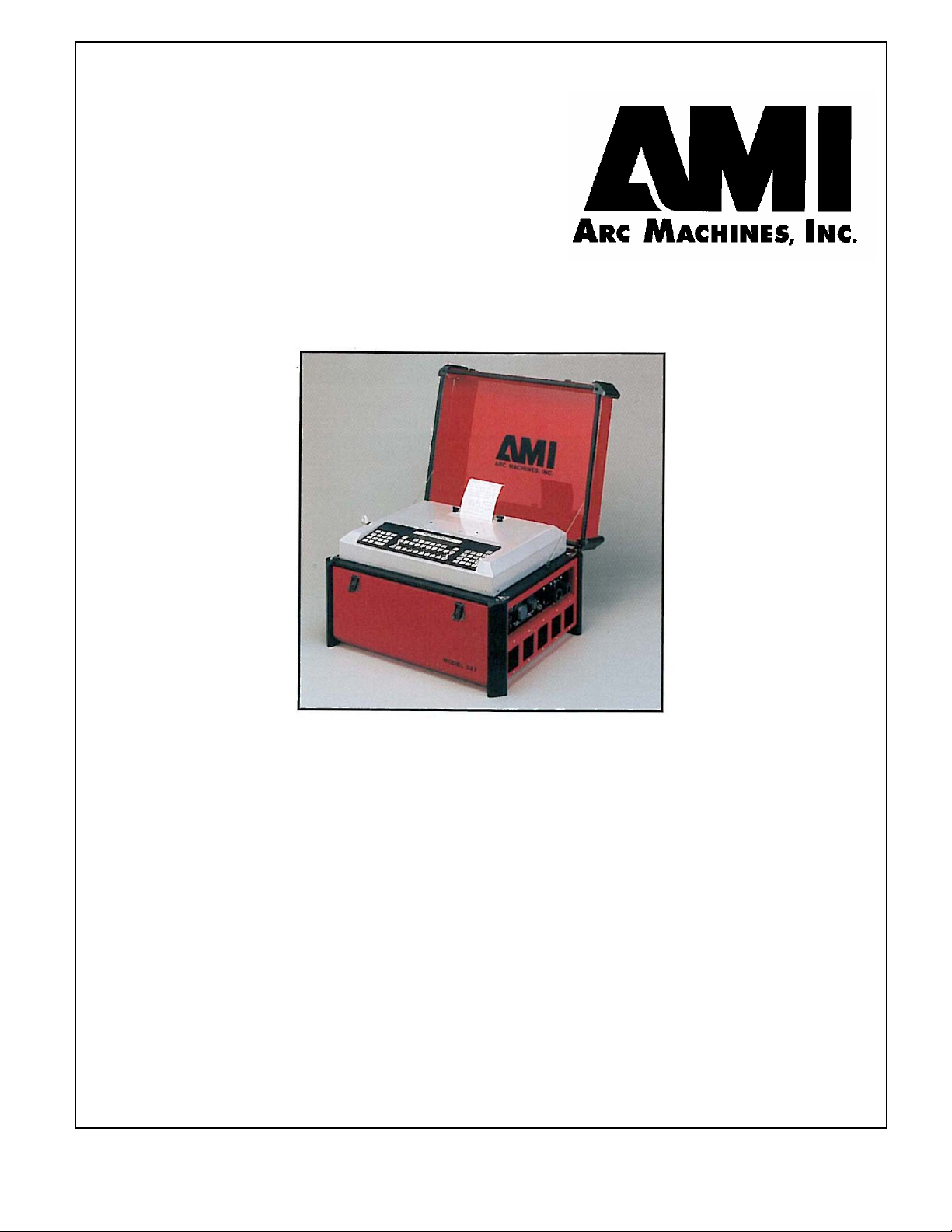
The Model 227 (M-227) welding power supply is part of a complete welding
system intended for the welding of tubes, pipes and fittings (see figure 1). The
complete system consists of the M-227 power supply, adapter cable, gas lines and a
variety of different AMI Welding Heads or Torch Fixture devices (Heads and
Fixtures are sold separately).
The standard version of the M-227 power supply provides GTAW current with
pulsation controls, high frequency arc starting, purge gas controls, weld head arc
rotation, cold wire feed, Arc Voltage Control, Torch Weave/Steering (Oscillation)
and automatic timing functions. Another version is available without the
AVC and
Oscillator functions. The M-227 includes a Remote Operators Pendant and comes
ready to weld. Users need only to supply input AC power, regulated gas source
with flow meter and the appropriate weld head or manual torch.
Some operation conditions may require optional components such as the M227/207-
CW Cooling Unit (for liquid cooled weld heads and torches). The M-227 family
of options also includes memory back up devices, off-line programming and quality
assurance options such as chart recorders.
The system can also be used as a manual welding power source using an optional
manual torch with a variety of manual welding options such as a variable current
foot controller with remote start/stop switch.
NOTE
In-depth weld development instructions, weld head set-up, maintenance and
troubleshooting are contained in other manuals, documents and training classes
and are not included in this manual. Contact your AMI representative for more
information about these items.
1.1

MODEL 227
OPERATION MANUAL
Doc # 740063 Rev E
SECTION I - INTRODUCTION
1.1 SAFETY PRECAUTIONS
This section contains cautions and warnings concerning the operation of this
equipment and welding equipment in general. However, in addition to reading
this manual and before operating this or any welding equipment, users should
reference and be familiar with “ANSI-49.1 Safety in Welding and Cutting”.
This standard is published by the American National Standards Institute and the
American Welding Society.
WARNING: Touching energized electrical parts can cause
fatal shocks and burns. When in weld sequence the electrode
and work are electrically energized. Incorrectly installed or
improperly grounded equipment is a hazard.
WARNING: This equipment is authorized to use a type of
arc starter that produces a High Frequency Radio Wave
(sometimes called HF and/or RF Starting). It can cause
interference and sometimes even damage to nearby electronic
equipment (such as computers) that are un-protected or poorly
protected against such interference.
WARNING: Magnetic Fields from High Currents can affect
pacemakers. PACEMAKER WEARERS KEEP AWAY
UNTIL CONSULTING YOUR DOCTOR.
WARNING: Disconnect the input power to the machine
before opening or servicing. Discharge all circuits that store
high voltage such as capacitor packs. Only QUALIFIED
service personnel should open this equipment.
WARNING: Welding can cause fires or explosions. Do not
weld near FLAMMABLE or EXPLOSIVE MATERIALS.
Watch for fire. Have proper type of extinguisher in work area.
WARNING: Welding Operators should wear non-flammable
protective clothing, footwear and head gear.
1.2

MODEL 227
OPERATION MANUAL
Doc # 740063 Rev E
SECTION I - INTRODUCTION
1.1 SAFETY PRECAUTIONS
WARNING: Never weld on sealed containers or pipes. This
may result in an EXPLOSION.
WARNING: Welding produces high temperatures in both the
welded components and the welding equipment. Both can
cause severe burns. Do not touch recently welded components.
Avoid touching internal components of the welding system
soon after use. Avoid touching torch components and welding
fixtures soon after welding.
WARNING: The welding arc emits ultra-violet (UV) radiation
and the molten weld gives off infra-red (IR). Both can burn
eyes and skin if unprotected. Suitable eye and skin protection
must be worn.
WARNING: Weld materials can emit toxic fumes during
welding. WELD ONLY IN AREAS WITH ADEQUATE
VENTILATION.
WARNING: Most GTAW gases like Argon are non-toxic,
however, Argon is heavier than air and will displace the
normal atmosphere in enclosed areas. DO NOT WELD IN
ENCLOSED AREAS WITH OUT PROPER VENTILATION
OR RESPIRATORS.
WARNING: AMI factory training is essential for all Welding
Operators and Maintenance Technicians who operate AMI
equipment.
WARNING: Before operating, storing or handling, always
make sure that the M-227, M-227-RP Pendant, weld heads and
cables are not exposed to rain or standing water. SYSTEM
COMPONENTS ARE NOT WEATHER-PROOF.
1.3

MODEL 227
OPERATION MANUAL
Doc # 740063 Rev E
SECTION I - INTRODUCTION
1.1 SAFETY PRECAUTIONS
WARNING: Keep hands and fingers clear from moving parts
such as fans, gears rotors, Wire Feed, Rotation and AVC
Mechanisms.
WARNING: The M-227 Power Supply is not intended for
pipe thawing or heating in any form.
WARNING: The M-227 Power Supply weighs in excess of
91 lbs (41.3 kg). It has no handles and is not intended to be
carried by a single person. Be sure to follow your local, OSHA,
international or employer guidelines for proper methods of
lifting and re-locating this equipment.
1.2 OPERATIONAL PRECAUTIONS
The following is a check list for operating personnel to follow to insure minimum
system down-time due to improper operation and handling:
1. TOO AVOID severe equipment damage VERIFY that the M-227 is
connected to the correct Input AC power (see section 3.1).
2. Before operating, check all fittings and connectors for proper seating and that
all protective boots are in place. If not properly seated or protected, short
circuits, poor connections or inert gas leaks could occur.
3. The M-227 is intended for typical GTAW gases ONLY. NEVER CONNECT
OXYGEN OR ACETYLENE TO THE M-227.
4. Before operating, insure that all cables are routed or protected in such a way
that they will not be subject to heat, equipment and/or personnel traffic. Insure
that the cables DO NOT come in contact with HOT PIPE.
5. When storing or handling cables, always keep the protective boots and dust
caps on all connectors and fittings until ready to install. A major cause of
downtime in any automatic welding system is improper care and use of cables.
1.4

MODEL 227
OPERATION MANUAL
Doc # 740063 Rev E
SECTION I - INTRODUCTION
1.2 OPERATIONAL PRECAUTIONS
6. Before operating, insure that the M-227 has adequate air flow. Do not restrict
the intakes or exhaust vents of the power supply.
7. Before operating, always insure that there is bare metal contact between the
weld head components which connect to GROUND (clamp inserts, etc.) and
the tube or pipe to be welded.
8. When storing or handling weld heads, always keep them in the protective
containers they are shipped in, or optional carrying case, until ready to install.
9. When operating, storing or handling, insure that the system is protected against
dirt, dust, etc. NEVER GRIND NEAR AN EXPOSED WELD HEAD OR
THE M-227.
10. Do not use acid, corrosives, liquid “Easy Out” or any liquid substance on the
M- 227 or any AMI weld head. When cleaning, use only a light solution of
Isopropyl alcohol on a soft cloth .
11. When handling, take extreme care to avoid dropping the M-227, weld heads,
cables or any accessories.
12. Do not attempt to move tube end into position using the weld head as a lever.
13. Do not add any lubrication like graphite, oil or grease to the weld heads or
power supply unless it is specified in the operation or maintenance manual
for that equipment.
1.3 RF AND EMI EMISSIONS
1. WHY RF?
“It has long been recognized that in the practice of welding and cutting,
there are circumstances where it is required to assist the process using
radio frequency voltage. In order to arc weld an electric arc must be created,
because of safety and economic concerns, the no load voltage of arc power
sources is kept as low as practical. Thus, a source of high voltage with a
high safety factor must be utilized. Radio Frequency voltage is the best
method of meeting these criteria for many reasons.” (quoted from
CISPR/B/63).
1.5

MODEL 227
OPERATION MANUAL
Doc # 740063 Rev E
SECTION I - INTRODUCTION
1.3 RF AND EMI TRANSMISSIONS
2. RF REGULATION
The FCC regulates the RF emission limitations for welding equipment by the
use of an IEC (international) regulation created by the Special Committee on
Radio Interference (known as CISPR) subcommittee B. The regulation of
record is:
CISPR/B/63
“CODE OF PRACTICE FOR THE USE OF WELDING AND CUTTING
POWER SOURCES UTILIZING RADIO FREQUENCY VOLTAGE FOR
STARTING OR STABILIZING THE ARC.”
The regulation states that due to the variety of work requirements and
conditions it is virtually impossible to establish fixed, normalized and
predictable tests and test setups for RF limits that would actually mean
something. Instead of limits they state the following:
“The manufacturer must design and produce equipment that is functional but
at the same time, design this equipment to keep electromagnetic radiation at
a minimum.”
“The user has the responsibility to install and use the power source per the
instructions of the manufacturer. Through this practice, it is reasonable to
assume that the probability of electromagnetic disturbances will be
significantly reduced. However, if some electromagnetic disturbances are
felt, then it is the responsibility of the USER of the equipment to resolve the
situation.”
3. RF PROTECTION
AMI policy is to comply with the IEC (and thus FCC) regulations. Our
design rules and procedures include testing and observing this area. We can
assure our customers that every effort has been made to reduce RF
emissions to the absolute minimum from our power sources.
However, this does not mean that a user will not have occasional problems
with RF interference with other equipment due to the use of our equipment.
This is the nature of RF starting.
1.6

MODEL 227
OPERATION MANUAL
Doc # 740063 Rev E
SYSTEM CONFIGURATON
1.7

MODEL 227
OPERATION MANUAL
Doc # 740063 Rev E
SECTION I - INTRODUCTION
1.3 RF AND EMI TRANSMISSIONS
3. RF PROTECTION (continued)
Most RF noise interference problems are going to be either set-up related or
caused by poor or no filtering on the behalf of the equipment that is being
interfered with. Most problems are easily correctable but each one must be
looked at on a “case by case basis.”
4. EMI SUPPRESSION
The M-227 is equipped with a heavy-duty Pi-Network filter, connected to
the input power line, to prevent propagation of EMI either into or out of the
M-227. The all-metal enclosures and internal shields prevent radiated EMI.
1.4 SHOCK HAZARD WARNING
As already stated in this manual “High Voltage” is present on exposed internal
terminals. The ELECTRODE (tungsten and M-9 rotors) is also an “exposed
terminal” and by its nature the GTAW process requires electrical potential to be
present on the electrode during arc starting and of course during the welding.
All AMI Power Supplies contain a “bleeder” circuit to ground any residual
potential after welding or after an aborted or bad “arc start” attempt. However,
these circuits take a few seconds to operate or COULD FAIL.
“THE ELECTRODE SHOULD ALWAYS BE CONSIDERED A POSSIBLE
SHOCK HAZARD”. This is especially true when ever the system is in “weld
sequence” ready to weld, is welding, or has just finished welding. However,
equipment/component failure, system abuse, or improper maintenance could result
in electrical potential at the weld head “even when not in weld sequence”.
The users/operators of this equipment must take all precautions necessary to avoid
contact with the ELECTRODE at “ALL TIMES”. The only exception is when
actually replacing or adjusting the electrode and this should be done “WITH THE
POWER TURNED OFF”.
If performed with the power “ON” the system must be in test mode out of weld
sequence and the USER MUST OBSERVE COMMON SAFETY PRACTICES
such as grounding the electrode to insure discharge before actually touching it.
REMEMBER, there is a “POSSIBLE” shock hazard in all welding power supplies
at “ALL” times.
Most AMI Power Supplies feature High Frequency (HF) Arc Starting. This is a
High Voltage/High Frequency electrical transmission process. To eliminate any
HF shock possibility “AVOID ALL CONTACT” with the Welding WORK
(ground), the ELECTRODE or the WELD HEAD during arc start.
1.8

MODEL 227
OPERATION MANUAL
Doc # 740063 Rev E
SECTION II - SPECIFICATION
The following contains only general specifications about the M-227 Power
Supply. More detailed information is available in AMI Specification No. 227.
2.0 ELECTRICAL
1. RATING PLATE DEFINITIONS
1) Company: Country:
Arc Machines, Inc. USA
3) Model:
Model 227
6) Standards:
NEMA EW1
IEC 974-1
8) Process:
10) Type:
DC
9) Output Continuous Current:
Minimum Maximum
3A / 5V 200A / 20V
Output Pulsed Current
Minimum Maximum
3A / 5V 225A / 20V
23) Shock Rating:
11) No-load Voltage:
U0= 59V
12) Duty Cycle:
X = 100% ALL RATED OUTPUTS
15) Input:
1~ 50/60 HZ
18) Voltage:
U1= 110V
220V
19) Input Current:
I1max = 30A I1eff =30A
30A 30A
21/22) Rating/Class:
IP21
1) - Manufacturer and Country of Origin.
3) - Model Number Rating Plate applies to.
4) - Serial Number (located on M-227 Center Plate, not on rating plate).
6) - International and USA Standards that the equipment meets.
8) - Weld Process symbol for GTAW welding.
9) - Rated MIN and MAX Outputs at Continuous Current with no pulsation.
Rated MIN and MAX Outputs when current is pulsing.
MAX current output using 110 VAC input is 100 Amperes.
10) - Symbol that output is Direct Current (DC) only.
11) - Rated No Load Output Voltage (open circuit voltage) is 59 volts.
12) - The M-227 is a 100 % Duty Cycle for the rated outputs (9).
15) - Input Voltage type contains symbol for single (1) phase Alternating
Current (AC) input at 50 or 60 Hz frequency.
18) - Nominal Input Voltage value is 110 VAC or 220 VAC.
19) - Rated maximum current required from the AC supply. Given for both
I1maximum (I1max) and I1effective (I1eff). 30 Ampere service is required
for both 110 VAC and 220 VAC operation.
2.1
S
G.T.A.W.

MODEL 227
OPERATION MANUAL
Doc # 740063 Rev E
SECTION II - SPECIFICATION
2.0 ELECTRICAL
1. RATING PLATE DEFINITIONS
21) - International Protection (IP) rating. The M-227 is rated IP21 which
includes protection against a limited amount of exposure to rain (does
not make it weather proof or intended for all weather usage).
22) - The M-227 is rated as class I. No symbol is used for class I equipment.
23) - “S” Symbol indicates a welding power source which is suitable for an
environment with an increased electric shock hazard.
2. INPUT POWER, DETAIL - The M-227, as shipped standard, can operate on
the following Single Phase input AC:
Voltage Tolerance Freq. Max Input Current
100 VAC + 32%, -10% 50/60 Hz 30 amperes
110 VAC + 20%, -18% 50/60 Hz 30 amperes
115 VAC + 15%, -22% 50/60 Hz 30 amperes
120 VAC + 10%, -25% 50/60 Hz 30 amperes
200 VAC + 32%, -10% 50/60 Hz 30 amperes
208 VAC + 27%, -13% 50/60 Hz 30 amperes
220 VAC + 20%, -18% 50/60 Hz 30 amperes
230 VAC +15%, -22% 50/60 Hz 30 amperes
240 VAC + 10%, -25% 50/60 Hz 30 amperes
+/- % indicates the allowable input voltage change to maintain performance as
specified. Maximum input current is based on maximum output current at
maximum arc voltage. See section 3.1 for installation.
3. OUTPUT POWER - Straight polarity, constant current DC regulation
intended for GTAW welding only. Static characteristic of the M-227 is flat.
Minimum current Output all cases .................... = 3 Amperes DC
Maximum current Output:
Set up for 110 VAC input ............. = 100 Amperes DC continuous or peak pulse.
Set up for 220 VAC input ............. = 200 Amperes DC continuous current
225 Amperes DC peak pulse
NOTE
The M-227 is limited, by software, not to be able to be programmed for an
average current (between primary and background) of greater than 200 Amperes.
However, a peak pulse can be up to 225 amperes as long as the average does
not exceed 200 amperes.
4. CIRCUIT BREAKER - ON/OFF, two pole, 30 Ampere at 250 VAC.
2.2

MODEL 227
OPERATION MANUAL
Doc # 740063 Rev E
SECTION II - SPECIFICATION
2.1 PHYSICAL CONSTRUCTION
Cabinet material - aluminum
Height = 13.9 inch (353.1mm) cover closed
12.3 inch (312.4 mm) cover removed
Width = 22.75 inch (577.9 mm)
Depth = 19.25 inch (489.0 mm)
Weight = 91 lbs (41.3 kg)
2.2 PROGRAMMABLE FUNCTIONS
PREPURGE TIME = 010 - 999 seconds
POSTPURGE TIME = 000 - 999 seconds
UPSLOPE TIME = 00.0 - 99.9 seconds
DOWNSLOPE TIME = 00.0 - 99.9 seconds
ROTATION START DELAY = 00.0 - 99.9 seconds
ROTATION MODE SETTINGS = CONT - STEP - OFF
ROTATION DIRECTION = CW - CCW
PRIMARY ROTATION SPEED = 0.00 - 20.0 RPM
BACKGROUND ROTATION SPEED = 0.00 - 20.0 RPM
WIRE FEED START DELAY = 00.0 - 99.9 seconds
PRIMARY WIRE FEED SPEED = 000 - 200 IPM
BACKGROUND WIRE FEED SPEED = 000 - 200 IPM
WIRE FEED STOP DELAY = 00.0 - 99.9 seconds
WIRE FEED RETRACT TIME = 0.0 - 1.0 seconds
PRIMARY AVC = 5.0 - 20.0 volts
BACKGROUND AVC = 5.0 - 20.0 volts
AVC START DELAY TIME = 00.0 - 99.9 seconds
AVC STOP DELAY TIME = 00.0 - 99.9 seconds
AVC MODE SETTINGS = CONT - SAMPLE - OFF
OSCILLATION MODE = ON - OFF
TORCH OSCILLATION AMPLITUDE = Determined by Head Type
OSCILLATION IN and OUT DWELL TIMES = 0.00 - 9.99 seconds
OSCILLATION EXCURSION TIME = 0.00 - 9.99 seconds
PULSE MODE SETTINGS = ON - OFF - SYNC (to osc)
PRIMARY PULSE TIME = 0.00 - 9.99 seconds
BACKGROUND PULSE TIME = 0.00 - 9.99 seconds
LEVELS = 1 - 99
LEVEL TIME (each level) = 000 - 999 seconds*
PRIMARY CURRENT = 3 - 225 amperes*
BACKGROUND CURRENT = 3 - 225 amperes*
* = Can be in increments of 0.1
2.3

MODEL 227
OPERATION MANUAL
Doc # 740063 Rev E
SECTION II - SPECIFICATION
2.3 MULTI-LEVEL FUNCTIONS - The following functions can be programmed to
change value during a given weld sequence.
FUNCTION POSSIBLE CHANGES
LEVEL TIME = 1 to 99 levels
PRIMARY CURRENT = 1 to 99 levels
BACKGROUND CURRENT = 1 to 99 levels
PRIMARY PULSE TIME = 1 to 99 levels
BACKGROUND PULSE TIME = 1 to 99 levels
PULSE MODE (ON/OFF/SYNC) = 1 to 99 levels
PRIMARY ROTATION RPM = 1 to 99 levels
BACKGROUND ROTATION RPM = 1 to 99 levels
ROTATION MODE (CONT/STEP/OFF) = 1 to 99 levels
PRIMARY WIRE FEED SPEED = 1 to 99 levels
BACKGROUND WIRE FEED SPEED = 1 to 99 levels
AVC MODE = 1 to 99 levels
PRIMARY AVC = 1 to 99 levels
BACKGROUND AVC = 1 to 99 levels
OSC AMPLITUDE = 1 to 99 levels
OSC DWELL and EXCURSION TIMES = 1 to 99 levels
2.4 NON-PROGRAMMABLE FUNCTIONS
WIRE FEED MODE SWITCH = ON/OFF
SYSTEM MODE KEY SWITCH = PROGRAM/OPERATE/LOCK
MANUAL PURGE = ON/OFF
2.5 AMBIENT TEMPERATURE RANGE - 32 F (0 C) to 110 F (45 C).
2.6 CABLE OPERATING DISTANCE LIMITS - Standard = 50 ft (15.2 m)
Maximum = 100 ft (30.5 m)
The standard distance consists of a 40 ft Pipe Weld Head Adapter cable and a 10 ft
Weld Head cable combined together. The maximum distance is achieved by
adding extension cables to the standard cables.
The above are considered normal limits and using a standard M227/207-CW or
M207-CW Cooling Unit Option. With special options, greater distances can be
achieved.Consult with an AMI technical representative for more information.
2.4

MODEL 227
OPERATION MANUAL
Doc # 740063 Rev E
SECTION III - INSTALLATION
3.0 INSPECTION
1. After unpacking, inspect all items for obvious physical damage and loose
parts. If damage is evident, contact a factory representative before using.
NOTE
If water condensation is apparent, dry the unit before using.
2. All M-227’s are shipped with a variety of peripheral equipment such as gas
hoses, fittings, manuals (including this one) and electrical drawings. An
exact list of these items is included with each power supply shipment. This
manual will reference some of those items, so before beginning installation, these
items should be located and be available.
3.1 POWER CONNECTION
WARNING
Do not connect the M-227 power supply to any AC power other than the ones
listed in section 2.0.2.
The M-227 can operate on 9 different input line voltages and must be set up for the
one you are using. Use the following procedure to insure that the M-227 is set-up for
the correct AC power.
1. The M-227 is supplied with a 25 ft power cord. One end has a connector on it
that plugs into the side of the M-227. The wires on the other end are pig-
tailed (no connector). A suitable AC line connector, matching the input
power, must be supplied and installed by the user. Color coding of the
power cord is as follows:
Black ................. = Hot (high line side)
White ................. = Neutral (low line side)
Green/Yellow .... = Ground (protective earth ground)
NOTE
For additional ground reference there is a ground symbol silk-screened next to
the ground pin on the M-227 Input AC connector on the Input Panel.
3.1

MODEL 227
OPERATION MANUAL
Doc # 740063 Rev E
SECTION III - INSTALLATION
3.1 POWER CONNECTION
2. Install the AC line connector onto the power cord.
NOTE
DO NOT PLUG THE M-227 INTO THE AC POWER SOURCE UNTIL
ALL INSTALLATION STEPS OF THIS MANUAL ARE COMPLETE.
3. Insure that the circuit breaker (CB-1) is in the OFF (down) position (see
figure 3).
4. Using figure 2 and 3 as a reference, locate the power SELECT SWITCH
(next to the input power connector). The switch is concealed by a cover
plate and only the top of the switch handle can be seen through a hole in the
plate. The plate is labeled as to what voltage it is currently set for.
5. If the M-227 is to be run on 100, 110, 115 or 120 VAC, this switch must be
in the 110 VAC position. If it is to be run on 200, 208, 220, 230 or 240
VAC, it must be in the 220 VAC position.
6. To change the power select switch position, remove the cover retaining
screws (see figure 3) and remove the cover. Set the switch to the alternate
position and install the cover plate. It must be flipped over so the hole in the
plate will fit over the switch handle in the new position. This will
automatically expose the alternate voltage label on the other side.
3.2 WELDING GAS CONNECTIONS
1. An Arc Input Gas Hose is supplied with the M-227. This hose is made of
material selected specifically for automatic welding. HOSES MADE
FROM OTHER MATERIAL ARE NOT RECOMMENDED (especially
rubber, nylon or tygon).
2. The 10 foot (3m) hose should be installed from the gas regulator/flowmeter
(user supplied) to the ARC GAS INPUT fittings required to mate with the
M-227 and most domestic (USA) inert gas flow meters.
The arc gas line is controlled by a solenoid and flow sensor in the M-227
and MUST BE connected to the M-227 (not directly to the weld head or
torch). After installing the hose and fittings loosely by hand, tighten the
retaining nuts slightly with a wrench to insure there are no leaks, but do not
over-tighten. The use of plumbers tape or grease is not recommended.
3.2
Table of contents
Other AMI Power Supply manuals