amiad TAF-500 Manual

Amiad Water Systems Ltd.
TAF-500 FILTERS
Serial number:
Order number:
Catalog number:
Filtration degree:
Tested by:
Installation, Operation and
Maintenance Instructions
910101-000115/06.2018

TAF-500 06.2018 / 910101-000115 Page 2 of 16
AMIAD Water Systems Ltd.
TAF-500 FILTERS
Installation, Operation and Maintenance Instructions
Disclaimer:
Copyright © 2018 Amiad Water Systems Ltd. All rights reserved.
The contents of this document, including without limitation all information and materials, images, illustrations, data, drawings, names and any other
such materials that appear in this document are the sole property of Amiad Water Systems Ltd., including any intellectual property rights, whether
registered or not, and all know-how contained or embodied therein. Amiad may alter, remove or change the Content without any further notice. You
may not reproduce, copy, modify, create derivative works from, sell or participate in any sale of, or exploit in any way, in whole or in part, any of this
document or its content.
The confidential nature of and/or privilege in the file enclosed is not waived or lost as a result of a mistake or error in this file.If you received this file
This document does not replace any certified drawing, procedure or information provided by Amiad in reference to a specific customer, site or
project.
Amiad assumes that all users understand risks involved within this file and/or its attached materials.This document is given in good faith and is not
intended to impose any obligation to Amiad. While every effort has been made to ensure the information in this manual is accurate and complete, we
would appreciate if you can bring any errors or omissions to the knowledge of Amiad or consult Amiad experts or its authorized representatives if you
have any questions.
Amiad Water Systems Ltd. D.N. Galil Elyon 1, 1233500, Israel Tel: 972 4 690 9500 | Fax: 972 4 814 1159 Email: info@amiad.com

TAF-500 06.2018 / 910101-000115 Page 3 of 16
TABLE OF CONTENTS
TABLE OF CONTENTS........................................................................................................................................................ 3
TECHNICAL SPECIFICATIONS............................................................................................................................................. 4
GENERAL ................................................................................................................................................................................. 4
FLUSHING DATA ........................................................................................................................................................................ 4
CONTROL AND ELECTRICITY.......................................................................................................................................................... 4
CONSTRUCTION MATERIALS ......................................................................................................................................................... 4
STANDARD FILTRATION DEGREES................................................................................................................................................... 4
SAFETY INSTRUCTIONS .................................................................................................................................................... 5
GENERAL ................................................................................................................................................................................. 5
INSTALLATION........................................................................................................................................................................... 5
OPERATION,CONTROL AND MAINTENANCE ................................................................................................................................... 5
USE OF LIFTING EQUIPMENT........................................................................................................................................................ 5
DIMENSIONAL DRAWING................................................................................................................................................. 6
DESCRIPTION OF FILTER OPERATION ............................................................................................................................... 7
FILTERING PROCESS.................................................................................................................................................................... 7
SELF-CLEANING PROCESS............................................................................................................................................................. 7
INSTALLATION ................................................................................................................................................................. 8
DESIGN RECOMMENDATIONS....................................................................................................................................................... 8
INSTALLATION INSTRUCTIONS....................................................................................................................................................... 8
START- UP AND FIRST OPERATION................................................................................................................................... 9
MAINTENANCE ...............................................................................................................................................................10
CHECKING THE FILTER ............................................................................................................................................................... 10
CHECKING THE PD SWITCH CONNECTORS ..................................................................................................................................... 10
WINTERIZATION...................................................................................................................................................................... 10
LEAKS.................................................................................................................................................................................... 10
PARTS SCHEDULE 2" TAF-500 FILTER SECTION 1..............................................................................................................11
PARTS DRAWING TAF-500 FILTER SECTION 1 ..................................................................................................................12
PARTS SCHEDULE & DRAWING 2" TAF-500 FILTER SECTION 2 .........................................................................................13
CONTROL DRAWING .......................................................................................................................................................14
AMIAD LIMITED WARRANTY...........................................................................................................................................15
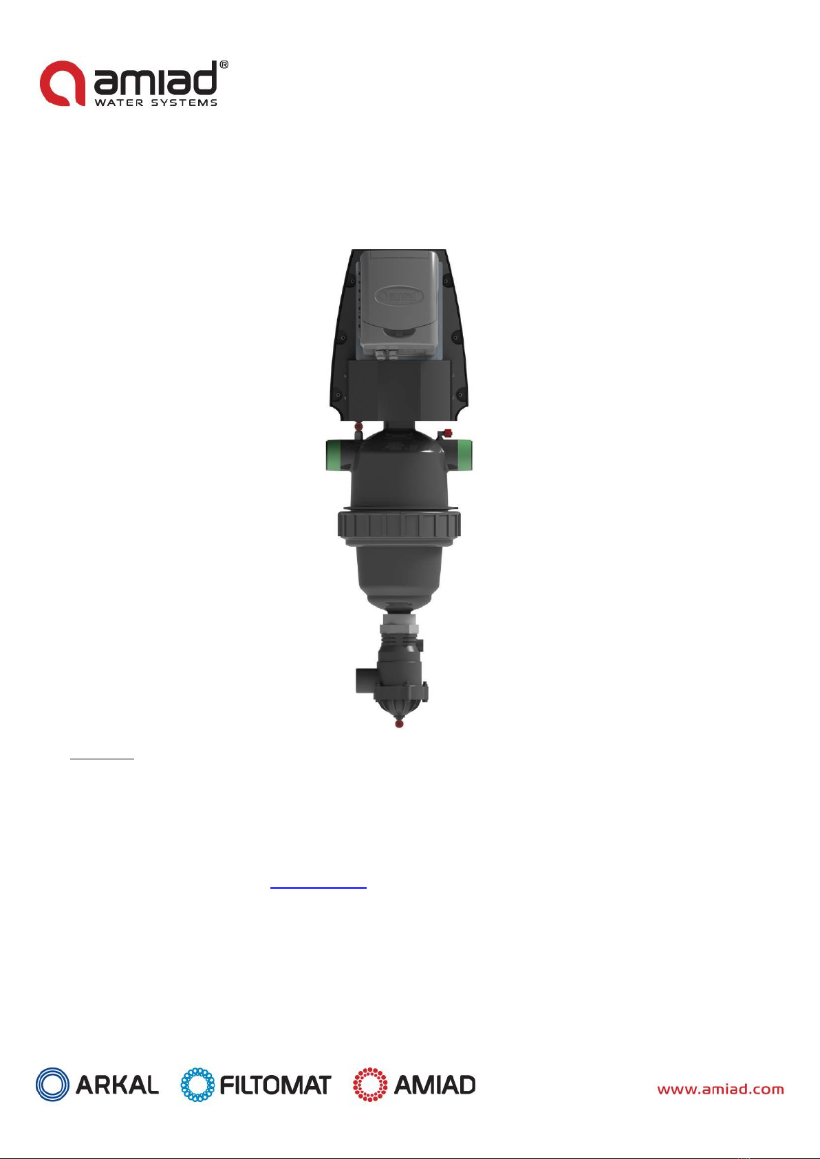
With any inquiry please quote Filter Serial Number, located on the filter housing.

TAF-500 06.2018 / 910101-000115 Page 4 of 16
TECHNICAL SPECIFICATIONS
General
Maximum flow rate
25 m3/hr; 110USgpm
Consult manufacturer for optimum flow depending on
filtration degree & water quality.
Min. working pressure
1.5 bar; 22psi
Or lower if pressure is increased for flushing.
Max. working pressure
8 bar; 120 psi
Filter area
465 cm2; 72 in2
Inlet/Outlet diameter
50 mm; 2"
Threads: BSP or NPT
Max. working temperature
600C; 1400F
Weight
11.6 kg; 25.6lb
Flushing data
Exhaust valve
40 mm; 11/2"
Flushing cycle time
16 seconds
Wasted water per cycle
18 liter; 4.7 USgallon
Minimum flow for flushing
4 m3/h; 18 USgpm
at 1.5 bar; 22 psi
Flushing criteria
Differential pressure of 0.5 bar (7psi), time intervals and manual operation
Control and electricity
Rated operation voltage
220 V - Single phase
110 upon request
Electric motor
15 Watt
50 / 60 Hz, Gear output 48 / 58 R.P.M.
Current consumption
0.18 A
Control voltage
24 VAC
Construction materials
Filter housing and lid
NYLON
Screens
St.St. 316 Weave Wire screen with Polypropylene construction
Cleaning mechanism
PP, Delrin
Exhaust valve
Plastic, Natural rubber
Seals
NBR
Control
Brass, Stainless steel, PE, PP
Standard filtration degrees
Stainless steel screen
micron
500
300
200
130
100
80
50
25
10
mm
0.5
0.3
0.2
0.13
0.1
0.08
0.05
0.02
0.01
mesh
30
50
75
120
155
200
300
450
600

TAF-500 06.2018 / 910101-000115 Page 5 of 16
SAFETY INSTRUCTIONS
General
1. Prior to installation or any treatment given to the filter, read carefully the installation and operation instructions.
2. While maintaining the filter all standard safety instructions should be observed in order to avoid danger to the workers, the
public or to property in the vicinity.
3. Please note, the filters enter into a flushing mode automatically, without prior warning.
4. No changes or modification to the equipment are permitted without a written notification given by the manufacturer or by its
representative, on the manufacturer behalf.
Installation
1. Install the filter according to the installation instructions detailed in this manual.
2. Make sure to leave enough clearance so as to enable easy access for future treatments and safe maintenance operations.
3. Electric wiring should be performed by an authorized electrician only; using standardized and approved components.
4. Install main power disconnect cut-off switch close to the control panel.
5. If the control panel is installed in a location where there is no eye contact with the filter, a power disconnect cut-off switch
should be installed near each filter unit.
6. Install the filter so as to avoid water splashing directly on the electrical components or on the control panel.
7. Additional safety devices should be installed on hot water applications to avoid skin burn danger.
Operation, Control and Maintenance
1. Disconnect the filter from power supply before maintenance or treatment.
2. Loosening or unscrewing bolts should be done only after the pressure in the filter had been released.
3. Avoid splashing and water leaking so as to minimize slipping, electrocution or damage to the equipment caused by moisture.
4. Always open and close valves slowly and gradually.
5. Remove grease and fat material residues in order to avoid slipping.
6. After treatment has been completed, re-assemble the protection covers of the drive mechanism.
7. Manual cleaning of filter element using high water pressure or steam, should be performed in accordance with the cleaning
system instructions and without endangering the operator or his vicinity.
8. Manual cleaning of filter element using acid or other chemical agents should be performed in accordance with the relevant
material safety instructions and without endangering the operator or his vicinity.
Use of Lifting Equipment
1. While using lifting equipment, make sure that the filter or the lifted part is chained securely and in a safe manner.
2. Do not leave lifted equipment hanging if not necessary. Avoid working below lifted equipment.
3. Wear a safety helmet while using lifting equipment.

TAF-500 06.2018 / 910101-000115 Page 6 of 16
DIMENSIONAL DRAWING
* Approx. Required Height For Maintenance
INLET OUTLET
N1 N2
N3
35.99
914 * (960/ 37.8")
DRAIN
[13.48]
342
10.94
278
8.87
225
20.49
520
3.55
90

TAF-500 06.2018 / 910101-000115 Page 7 of 16
DESCRIPTION OF FILTER OPERATION
The "TAF" is a sophisticated yet easy-to-operate automatic electric filter, with a self-cleaning mechanism driven by an electric motor.
The filter is designed to work with various types of screens in filtration degrees from 500 to 10 micron.
Filtering process
The water enters through the inlet pipe into the screen area and flows through the screen from inside out. The "filtration cake" is
accumulated on the screen surface and causes head loss to develop.
Self-cleaning process
The TAF initiates the self-cleaning process either when the pressure differential across the screen reaches a pre-set value or after a
predetermined lapse of time.
The fine screen filter element is cleaned by the suction scanner whose nozzles spiral across the inner surface of the screen. The
filtration cake is "vacuumed" from the screen and expelled out the exhaust valve.
The scanner's spiral motion is achieved by a drive unit which rotates a bi-directional continuous worm shaft.
The exhaust valve is activated for the duration of the cleaning cycle by a 3-way solenoid. Filtered water continues to flow
downstream during the flush cycle, which takes approximately 16 seconds.

TAF-500 06.2018 / 910101-000115 Page 8 of 16
INSTALLATION
Design recommendations
1. The filter requires 4 m3/h (26USgpm) for flushing, in addition to the working flow rate at a minimum pressure of 1.5 bar (22 psi). In
the event that the system cannot provide the flushing flow in addition to the working flow, at the minimum required pressure, a
hydraulic valve should be installed downstream of the filter. This valve will be closed during the flushing process in order to
ensure sufficient cleaning.
2. Do not allow water to flow in opposite direction. In case that there is a chance of back flow a non-return check valve should be
installed downstream of the filter.
Installation instructions
1. Install a manual valve upstream of the filter to enable convenient maintenance.
2. The diameter of the inlet pipe must not be smaller than that of the filter inlet.
3. Install the filter in a way that enables convenient approach and enough space to dismantle the filter for maintenance purposes.
4. It is recommended to install the filter horizontally, especially if the water contains sand.
5. Ensure the direction of flow is according to the arrows marked on the filter housing.
6. The exhaust valve can be facing downwards or sideways. Connect a minimum of 1.5" (40 mm) pipe to the exhaust valve using a
detachable connector or a flexible pipe. The exhaust pipe should be designed so that it creates minimal resistance to the flow
of 4 m3/h (26USgpm).
7. If the system is designed to operate with a working pressure higher than 6 bar (85 psi), it is recommended that a manual valve
will be installed on the exhaust pipe, to enable regulation of the flushing flow rate.

TAF-500 06.2018 / 910101-000115 Page 9 of 16
START- UP AND FIRST OPERATION
1. Set the controller to 16 seconds flushing time and 2-4 hour intervals.
2. Operate a "dry" flushing cycle. Verify proper operation of the controller, the motor and the solenoid valve.
3. Open the inlet valve to the filter, while the outlet valve remains closed or with an open by-pass valve (This will keep the flow in
the filter at a minimum), and operate a flushing cycle by pressing the push-button on the controller panel.
4. Make sure the exhaust valve opens and all stages of the flushing cycle are carried out. Attend to leakage, if any.
If necessary, change the time setting to ensure complete up and down motion of the suction scanner.
5. Gradually open the outlet valve and/or close the by-pass valve. Operate the filter at the designed hydraulic conditions.

TAF-500 06.2018 / 910101-000115 Page 10 of 16
MAINTENANCE
NOTE: Depressurize the filter before maintenance (Close inlet and then outlet valves).
Checking the filter
1. Unscrew the filter cover.
2. Extract the screen and clean if necessary. Cleaning is performed by hosing the screen from outside-in, and/or
with a nylon brush.
3. Check the Screen O-ring (17.1) and apply grease, if necessary.
4. Replace the screen.
5. Return the cover and twist to tighten.
Checking the PD switch connectors
Check the L-Connectors (9.3, 9.4) to the PD Switch to make sure that there are no obstructions.
Winterization
Filter operations should be suspended in climates where the filter is exposed to freezing temperatures.
1. Check that the outlet valve is closed and perform two manual rinses.
2. Close the inlet valve to the filter and release the pressure.
3. Remove all drain lines from the valves, drain, and reconnect.
Leaks
In case of a leak contact Amiad technical support.

TAF-500 06.2018 / 910101-000115 Page 11 of 16
PARTS SCHEDULE 2" TAF-500 FILTER Section 1
NO.
Cat. Num.
Description
QTY
Material
1
710103-001202
Housing 2" TAF-500/750 NPT
1
NYLON
1
710103-001200
Housing 2" TAF-500/750 BSPT
1
NYLON
2
700190-001831
Pressure Balancing Assembly 2" TAF Electric
1
Various
2.1
770102-000092
O-Ring Seal P2-125 Scanner Bearing NBR"S"
1
NBR
3
700190-001848
Suction Scanner (2"TAF)
1
Various
4
SEE TABLE
Screen TAF-500
1
Various
4.1
770102-000130
O-Ring Seal P2-242 (2"/3 Screen) NBR"S"
2
NBR
5
770102-000169
O-Ring Seal P2-437
1
NBR
6
710103-000545
Lid 2"T BSPT
1
NYLON
7
710103-000544
Tightening nut (T filters)
1
NYLON
8
770102-000069
O-Ring Rubber Seal P2-028
1
NBR
9
710103-000704
Long Bearing For Suction Scanner 2"T
1
Delrin
10
770102-000096
O-Ring Seal P2-129 NBR
1
NBR
11
780101-000955
Connector 11/2"FX11/2"M
1
ST.37-2
12
730103-000444
1-1/2" Exhaust Valve
1
Various
13
720501-000198
L-Connector 1/4"X8MM Red/Black
6
NYLON
14
720501-000232
T-Connector 8MMX8MMX1/4"M Black-Red
1
PP
15
730110-000034
Finger Filter
1
Various
16
710101-000765
Motor Connecting Flange 2" TAF NPT
1
NYLON
16
710101-000760
Flange Adaptor (HYDROTAF)
1
NYLON
17
760103-000094
Flat Washer M6 DIN125S/ST316
12
SST316
18
760101-000445
Hex Bolt Full Thread M6X25 S/ST316 DIN933
4
SST316L
19
710103-001207
Endless Worm Shaft Housing TAF
1
Delrin
20
770101-000051
O-Ring Seal 3.5X45 TAF Motor Housing NBR
1
NBR
21
710101-000767
Seal U-Cup (Scanner Shaft) Hydro-TAF
1
NBR
22
770101-000049
O-Ring Seal 30X3 NBR "S"
1
NBR
23
710103-001247
Reversible Worm Shaft
1
Acetal
24
760105-000029
Slotted Pin 3x20 DIN1481 S/ST 304
1
S/ST 304
25
710103-001209
Endless Worm Shft Tooth
1
S/ST 303
26
760107-000065
Spring Tooth S/St302
1
Hastelloy C-276
27
710103-001210
Tooth Cover TAF
1
S/ST 316L
28
760101-000443
Hex Bolt Full Thread M6X15 S/ST304 DIN933
4
SST304
29
710103-001216
Motor Shaft Coupler
1
S/ST 316L
31
710103-001217
Drive Unit Basis TAF
1
S/ST 316L
32
720201-000033
Drive Unit TAF-750 220V AC 1/25
1
Various
32
720201-000032
Drive Unit TAF-750 110V AC 60HZ 0.015KW 1/25
1
Various
33
760101-000607
Hex Bolt Full Thread M6X60 S/ST316 DIN933
4
SST316L
34
760102-000085
Hex Nut M6 S/ST316 DIN934
4
SST316L
35
710103-001212
Instrumentation Bracket
1
S/ST 316L
36
720104-000029
PD Switch UE 24-011
1
Various
37
760101-000529
Phillips Pan Machine Screw M4X10 316
2
SST316L
38
760102-000083
Hex Nut M4 S/ST304 DIN934
2
SST304
39
720103-000187
3/2 Nc Solenoid Valve (Type B) 24VAC 50Hz
1
Various
39
720103-000189
3/2 NC Solenoid Valve 60HZ NC 24VAC
1
Various
40
720501-000209
L-Connector 1/8"MX6MM Black-Red
1
PP
41
710103-001204
Drive Unit Cover TAF
1
Various
42
710103-004837
Sling For AMIAD Controler AC-DC6_GL-TAF
1
S/ST 304L
43
720101-000475
Electronic Control 220VAC 6-Out 1-In Galcon
1
Various
43
710101-000476
Electronic Control 110VAC 6-Out 1-In Galcon
1
Various
44
760101-000713
Phillips Pan Machine Screw M5X8 S/ST316
4
SST316L
45
760101-000530
Phillips Pan Machine Screw M5X8 304
4
SST304
46
770101-000036
MM O-RING SEAL ID10MM TH2MM NBR 70 SHORE
1
NBR

TAF-500 06.2018 / 910101-000115 Page 12 of 16
PARTS DRAWING TAF-500 FILTER Section 1

TAF-500 06.2018 / 910101-000115 Page 13 of 16
1 1.1
1.2
1.3
3
2
PARTS SCHEDULE & DRAWING 2" TAF-500 FILTER Section 2
NO.
Cat. Num.
Description
QTY
Material
1
700190-001850
Suction Scanner W/O Shaft (2" TAF-500)
1
Various
1.1
710101-000751-1
2"-4" Suction Scanner Nozzle No.1
4
PP
1.2
710101-000751-2
2"-4" Suction Scanner Nozzle No.2
4
PP
1.3
760101-000537
Phillips Pan Tap Screw PT4x20 S/ST316
8
S/ST 316
2
710103-001208
Suction Scanner Shaft 2" TAF
1
S/ST 316L
3
760105-000033
Slotted Pin 3x30 DIN1481 S/ST 304
1
S/ST 304

TAF-500 06.2018 / 910101-000115 Page 14 of 16
CONTROL DRAWING

TAF-500 06.2018 / 910101-000115 Page 15 of 16
Amiad Limited Warranty
This certificate applies to Amiad Products purchased by You from Amiad or an Amiad authorized Distributor (“Distributor”). This
limited warranty extends only to the original purchaser, and is not transferable to anyone who subsequently purchases, leases, or
otherwise obtains the Product from the original purchaser.
1. Amiad hereby warrants that the Products are and will be free from defects in material and workmanship under normal use and
service. Amiad warrants that it will correct manufacturing defects in the Products, in accordance with the conditions set out in
this warranty.
2. This warranty is enforceable for a period of 12 months after the date Bill of Lading or equivalent (the “Warranty Period”).
3. In the event that during the Warranty Period the Distributor discovers a defect in material and/or workmanship in any Product or
part (the “Defective Product”), it shall submit a written complaint to Amiad using Amiad's standard customer complaint form. For
the receipt of the customer complaint form, the submission of the complaint or any questions please contact your customer
service representative.
4. Upon written demand by Amiad the Distributor shall return the Defective Products –or a sample thereof –to Amiad, at Amiad's
cost. If the customer ships any such Product, Amiad suggests the customer package it securely and insure it for value, as Amiad
assumes no liability for any loss or damage occurring during shipment. Provided however that in the event Amiad determines
that the warranty does not apply to such Product, Distributor shall promptly reimburse Amiad for such cost (including freight and
customs). Any returned Product or part must be accompanied by the warranty certificate and the purchase invoice. It is clarified
that the Distributor may not return the Defective Product unless such return was coordinate and approved by Amiad in advance.
5. Amiad's obligation under this warranty shall be limited to, at its option, the repair or exchange, free of charge, of the Product or
any part which may prove defective under normal use and service during the Warranty Period. The provision of a repaired or
replacement Product during the Warranty Period will result in an extension of the Warranty Period by an additional period of 12
months, provided that the total accumulated Warranty Period shall in any event be no more than 18 months from the original Bill
of Lading.
6. This warranty is valid on the condition that the Products are installed according to Amiad's instructions as expressed in Amiad's
instruction manuals and according to the technical limitations as stipulated in Amiad's literature or as stated by a representative
of Amiad.
7. This warranty will not apply to damaged or defective Products resulting from or related to:
(i) Fire, flood, power surges or failures or any other catastrophe/and or unforeseen occurrence, such as but not limited to those
for which the customers are customarily insured;
(ii)Fault, abuse or negligence of the customer;
(iii)Customer's responsibilities, including the failure of the intake water to meet the agreed standards, as set forth in a written
document, approved by Amiad or improper storage.
(iv)Improper or unauthorized use of the Product or related parts by the customer, including the customer’s failure to operate the
Product in conformity with the recommendations and instructions of Amiad, as set forth in Amiad's manuals and other
written materials, the operation of the Product other than by a trained and qualified operator, or improper installation of
the Product by a third party not authorized by Amiad;
(v) Performance by the customer of maintenance and other services other than by a trained and qualified advanced operator, or
other than in conformity with the recommendations and instructions of Amiad, or other than in accordance with
procedures defined in the literature supplied for Products;
(vi)Any alteration, modification foreign attachment to or repair of the Products, other than by Amiad or its authorized technical
representatives.
8. In no event shall Amiad be liable to the customer or any third party for any damages, including indirect, special, exemplary,
punitive or consequential damages, or lost profits arising out of or in connection with this warranty, or arising out of or in
connection with the Product's performance or failure to perform, even if it has been advised of the possibility of such damages.
9. Amiad will be excused for failure to perform or for delay in performance hereunder if such failure or delay is due to causes
beyond its reasonable control or force majeure preventing or hindering performance.
10.The limited warranty set forth herein is the only warranty given by Amiad and is provided in lieu of any other warranties created
by any documentation, packaging or otherwise.
11.Amiad makes no warranty whatsoever in respect of accessories or parts not supplied by Amiad. In the event that Amiad is
required to correct a defective Product or product not covered by this warranty, it will do so solely in consideration for additional
fees.
Table of contents
Other amiad Water Dispenser manuals