amiad AMF2-93K User manual

AMIAD Water Systems
AMF² MICROFIBER FILTERS
AMF²-93K
Serial number:
_______________
Order number:
_______________
Catalog number:
_______________
Filtration degree:
_______________
Tested by:
_______________
Cassettes Replacing Guide
Ref. 910101-000626/10.2013

- 2 -
AMIAD Water Systems
AMF²-93K Cassettes Replacing Manual
This document describes the process of replacing damaged cassettes in Amiad’s AMF 93K micro-fiber filter and it contains
the following sections:
A. General information and safety instructions
B. Preparing the filter for cartridge disassembly
C. Removing the cartridge out of the filter’s housing
D. Disassembling the cartridge and replacing the damaged cassettes
E. Reassembling the cartridge
F. Reassembling the filter
G. Restarting the filter
H. Cassette Package explosion assembly drawings
Disclaimer:
This document and the information enclosed within it contain restricted and/or privileged information that are intended only for usage by authorized Amiad technicians. If you are not a qualified Amiad
technician you must not take nay action in reliance to this document, unless permitted by Amiad.
None of the procedures provided on this file may be used in any form or by any means without permission from Amiad.
The confidential nature of and/or privilege in the file enclosed is not waived or lost as a result of a mistake or error in this file. Amiad accepts no liability whatsoever, whether it was caused by:
1. Accessing or other related actions to this file.
2. Any links, procedures or materials provided/attached to this file.
Amiad assumes that all users understand risks involved within this file and/or its attached materials.
All the procedures, drawings, pictures and/or any other information provided in this document are presented as general information only; they can be altered, removed or changed without any further
notice by Amiad.
This document does not replace any certified drawing, procedure or information provided by Amiad in reference to a specific customer, site or project.
All rights reserved.

- 3 -
A. General Information and Safety Instructions:
Before you begin –Safety instructions
Prior to installation, operation, maintenance or any other type of action done on the filter, read carefully the
installation and operation instructions.
During installation, operation or maintenance of the filter, all conventional safety instructions should be
observed in order to avoid danger to workers, the public or to property in the vicinity.
Please note: The filter enters automatically without any warning into a flushing mode.
No changes or modification to the equipment are permitted without a written notification given by the
manufacturer or by its representative on his behalf.
Service the filter according to the detailed Instructions provided with the filter by the manufacturer and
according to the description given in this manual.
Electric wiring should be performed by an authorized electrician only, using only standard and approved
components.
If due to site constrains the control panel is installed with no line-of sight with the filter an additional Power Cut-
off Switch should be installed near each filter unit before any attempt to service the filter is done.
Extra safety devices should be installed on hot water applications to avoid skin burn danger.
Disconnect the filter from power supply before performing any service, maintenance or any non-regular
operation action.
Loosening or unscrewing bolts should be done only after the pressure in the filter had been released.
Avoid splashing and water leaking so as to minimize slipping, electrifying or damage to the equipment, caused by
moisture.
Always open and close valves slowly and gradually.
Remove grease and fat material residues in order to avoid slipping.
Re-assemble any protection covers or protection mechanisms removed during service or maintenance
operations before re-operating the filter.
Manual cleaning of filter media using high water pressure or steam should be performed in accordance with the
cleaning system instructions and without endangering the operator or the vicinity.
Manual cleaning of any filter element using acid or other chemical agents should be performed in accordance
with the relevant material safety instructions and without endangering the operator or the vicinity.
While using lifting equipment, make sure that the filter or the lifted part is chained securely and in a safe
manner.
Do not leave lifted equipment if there is no necessity.
Avoid working below lifted equipment.
Wear a safety helmet while using lifting equipment.
Arrange suitable lighting at the area of the filter to enable good visibility and safe maintenance.
Provide suitable platforms and safety barriers to enable easy access to the filter without climbing on pipes and
other equipment.
Check and re-tighten all bolts after finishing the maintenance or service work.
Always maintain regular safety instructions and good engineering practices while working in the filter’s vicinity.
Required tools:
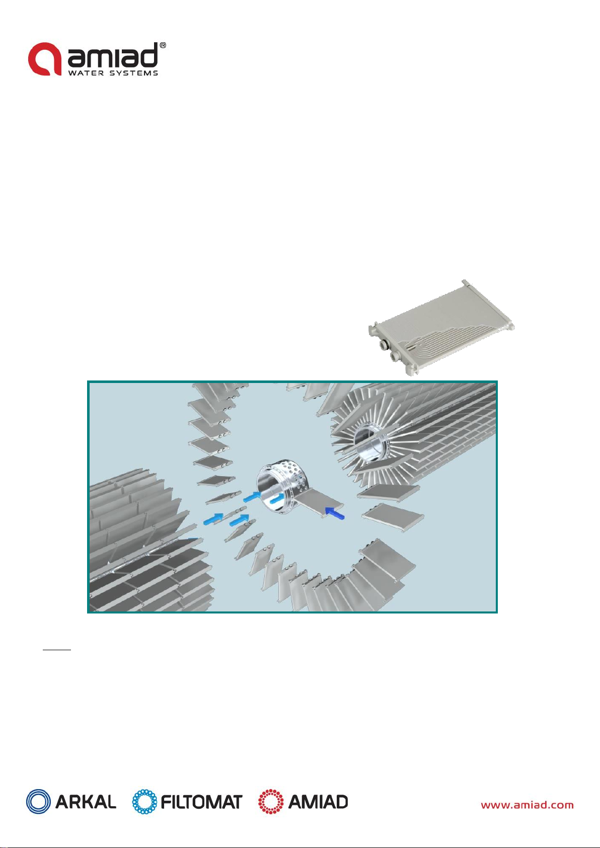
In addition to a regular standard tool box, 2 special tools are required for a successful completion of the cassette
replacing process:
1. MTG/AMF grooved Cassette Alignment Ring - catalogue number –65-8040--4004

- 4 -
2. MTG/AMF Cassette Holder Ring - catalogue number –65-8040--4001
1 - MTG/AMF Cassette Alignment Ring 2 - MTG/AMF Cassette Holder Ring
Please contact your supplier for ordering these tools.
Understanding the cartridge cassettes’ arrangement:
Important Note:
Prior to performing the actual work it is very important to understand the special arrangement of the cassettes in the
filter’s cartridge! Improper assembly of the cartridge will lead to filter malfunction and to a significant damage!
Two types of cassettes are used in the cartridge:
1. Centralized nipples cassette type (as appears at the picture’s right side)
2. Shifted nipples cassette type (as appears at the picture’s left side)
Make sure that you have the correct spare parts before disassembling the cartridge.
35 cassettes are connected to a single joined-in collector pipe and form a package. The connector holes in the join-in
connector are arranged so the two types of cassettes are used alternatively:

- 5 -
Please note that the missing cassette in the above picture is a shifted nipples cassette.
See also the alternating arrangement of the holes in the internal part of the join-in connector unit.
Opposite to the connector nipples, at the outer edge of the cassette, two U shape connectors are found. One of these
connectors is of a female type and the other is a male type.
34 of the cassettes in each package are arranged with the male connector pointing to the same direction while the 35th
cassette is mounted in the opposite way where its female connector is pointing to the direction of the other cassettes
male connectors.
The 35th cassette serves as the Leading Cassette and during the assembly process of the cartridge it is very important to
position it in the right location as explained further down in this manual.
Please note that the upper middle cassette in the above picture is the Leading Cassette of the package. Please see that
the other cassettes male connectors are pointed up while the Leading Cassette is in the opposite direction.
26 packages are attached to each other surrounding a Central Pipe assembly and form a cartridge.
The packages are attached to each other where their Leading Cassettes are aligned together to form the central axis of
the cartridge. The cartridge central axis is aligned with marking holes in the other parts of the complete cartridge.

- 6 -
In the above picture you can see how the Leading Cassette (shown in the middle of the picture) is aligned with the
marking hole on the cog-wheel.
The above picture shows how the Leading Cassettes are connected together along the cartridge and perfectly aligned
with the markings of the other parts.

- 7 -
B. Preparing the filter for cartridge disassembly:
1. Disconnect the filter form the process water system by closing the upstream (the entry point of unfiltered water to the
filter) and downstream (the exit point of clean water from the filter) manual valves.
2. Drain the filter housing by manually opening the drainage butterfly valve located at the lower side of the filter
body.
3. Make sure that Piston#40 is pushed out of the cartridge to ensure that the spray nozzles are not within the
cassette package limits:
i. Remove the plug from the flange of the tail assembly.
ii. Insert a clean and straight 4.5 meter 0.5” pipe or rod (the Tune-up rod) through the opened connection.
iii. Using the rod push the piston all the way in.
iv. Remove the rod out of the filter and reassemble the plug.
4. Lock the Index Piston in its “out” position:

- 8 -
i. Properly mark the upper and lower 8mm water control tubes and disconnect them from the Index
Piston. Important: Mistakenly re-assembling these control tubes may cause serious malfunction of the
filter.
ii. Connect a compressed air tube to the lower port of the Index Piston to push the piston to its “Out”
position. This will allow you to freely rotate the cartridge as required at stage C.1.8.Leave the Index
Piston locked at this position till the end of the cassette replacement process.
“Up” label
“Down” label
Compressed
Air Tube

- 9 -
C. Removing the cartridge out of the filter’s housing:
C.1. Identifying the damaged cassettes:
1. Disconnect the High Pressure Pipe from the far end of the Piston House Assembly.
2. Disconnect the control tube from the Piston House Assembly.
Disconnect the Proximity Switch SW1 from the Piston House Assembly by unscrewing the sensor from its Mounting block.
Important note: Make sure that the Mounting Block of SW1 stays in its current position! Any movement of the
block will affect the piston’s calibration and will cause damage to the filter. Only the sensor should be
removed!!!
Remove this sensor
only
Do not move this
Block!

- 10 -
3. Unscrew the filter’s Intermediate Cover bolts and open the Cover by gently pulling it out together with the Piston
Hosing and the Piston#50 Assemblies. (Hold the Cover Handle with one hand (1) and support the Piston Housing
with your other hand (2).)
Don’t Move this Block
(1)
(2)

- 11 -
4. Make sure that the V-Shape Plate of the cartridge points to the central line of the filter, if necessary turn it by
hand accordingly (1). Remove Piston#40 by pulling it straightly but gently out of the filter. Make sure not to
damage the cassettes by letting the spray nuzzles to hit the cartridge (2) while pulling the piston (you may need
assistants to keep the piston balanced while pulling it out of the filter).
5. Using a flashlight inspect the interior of the filter for damaged cassettes. Firmly hold the nozzle guide Cog-Wheel
and rotate the cartridge till all the cassettes’ rows are checked. If damaged cassettes are found please continue
with the cartridge removal procedure.
Hold and
rotate the Cog
Wheel
(1)
(2)

- 12 -
Important note: In case it is too difficult to rotate the cartridge by hand, operate the Index Piston by alternating
the compressed air tube connection. Connect the tube to the upper port to move the index by one row and
reconnect the tube to the lower port to advance the index by another row. Continue this operation till all the
cartridge rows are checked for damaged cassettes.
C.2. Removing the cartridge with the damaged cassettes:
1. Make sure that the Index Piston is forced out of the cartridge (See stage B4 for details). Prior to the removal of
the cartridge out of the filter housing it is necessary to force the Index Piston out of the Gear Turn cog-wheel.
Any attempt to pull out the cartridge while the Index Piston is “in” will cause damage. Verify that the Index
Piston is locked at the “out” position by checking the proximity switch. The Index piston has two switches; the
closer one to the filter housing indicates that the piston is “in”, while the farthest switch indicates that the piston
is “out”. Make sure that the green led of the farthest switch is lighted up.
“In” Switch
“Out” Switch
Make sure that this
green led is lighted
Alternate the connection
to advance the Index

- 13 -
2. Unscrew the bolts and remove the cartridge lid. (You may need assistance since the lid may be heavy for one
person to carry so take an extra care!)
3. Unscrew and release the bolts of the three disc stoppers (1), turn each one of the stoppers by 180° and make
sure that they are not extended beyond the boarders of the Plate Partition (2).
(1)
(2)
Disc Stoppers
Out
In
Turn the Stopper 180°

- 14 -
4. Hold the cartridge Triangle Plate and start to pull the cartridge out of the filter housing (1). Once the cartridge is
released and starts to move, lift it slightly with one hand and continue to pull it out with the other hand till the
first Cassettes’ Package passes the opening (2), then continue to pull out the cartridge in a straight line (3).
5. With a help of an assistant pull the cartridge out of the filter housing and gently put it on some support where
the cassettes do not touch the ground.
(1)
(2)
(3)

- 15 -
D. Disassembling the cartridge and replacing the damaged cassettes:
1. Unscrew and remove the 4 Self Tapping Screws from the Nozzle Guide cog-wheel.
2. Remove the Guide Plate from the Central Pipe using a hammer and soft-edge plastic or wooden stake.

- 16 -
3. Use a screwdriver to gently release the Nozzle Guide cog-wheel from the first Cassette Pack and pull it out of the
Central Pipe.
4. Use a screwdriver to gently release the 2 O-ring seals from the Half Cassettes Connector
5. Use a screwdriver and gently release the Half Cassettes Connector from the first Cassette Pack, then pull the
connector out of the Central Pipe.

- 17 -
6. Hold the first Cassette Package with both arms, pull it out of the Central Pipe and put it gently on a clean surface.
7. Use a screwdriver or a bended steel wire to gently pull out and release the two locking pins of the Cassettes
Connector out of their holes in the Central Pipe. Pull out slightly the Cassettes Connector and turn it clockwise to
eliminate the pins to be trapped again by holes on the Central Pipe. Pull the Cassettes Connector and remove it
of the Central Pipe.
8. Hold the second Cassette Package with both arms, pull it out of the Central Pipe and put it gently on a clean
surface.

- 18 -
9. Unscrew and remove from the Central Pipe 2 Machine Screws located between Cassette Packages 2 and 3.
10. Repeat steps 7-8 and remove all the Packages that contain damaged cassettes. Please note that if there are
damaged cassettes in the far end of the cartridge you will have to repeat step number 9 and remove the 2
Machine Screws located between Cassette Packages number 25 and 26.
11. Pull out any damaged cassette and insert a new one in its place. Firmly press in the new cassette and check that
its connection nipples are fully inserted to the Join-in Connector Unit. It is very important to make sure that the
new cassette’s type (Centralized or Shifted Nipples) and filtration degree remain the same as of the original
cassette.

- 19 -
E. Reassembling the cartridge:
1. Insert the Cassette Alignment Ring over the Central Pipe and locate it on the last installed Cassettes Package.
While pushing the ring to its place make sure that all the cassettes are inserted to their respective groves in the
Alignment Ring. Once all the cassettes are in the grooves gently push-in the ring few more centimeters and
locate it at the far end of the first package close to the point where the package is connected to the previous
one.
2. Insert a new Cassettes Package over the Central Pipe. Make sure that the female U-shape connector of the
Leading Cassette is pointing forward to the central alignment line created by the Leading Cassettes of the
previously installed packages.

- 20 -
3. Locate the new Cassettes Package close to the previously installed one and verify that the Leading Cassettes of
the two packages are aligned with each other. (Look at the red circle in the following picture and notice how the
Leading Cassette with the female U-shape connector pointing to the right, is aligned with the previous Leading
Cassette with the male U-shape connector pointing to the left.)
4. Pull the Cassette Alignment Ring few centimeters backward and locate it so it covers the U-shape connectors of
both cassettes packages.
5. Insert the Cassette Holder Ring over the Central Pipe and use it to push the Cassettes Package till the U-shape
connectors of the last two Packages are firmly joined together.
Table of contents
Other amiad Water System manuals
Popular Water System manuals by other brands

A.O. Smith
A.O. Smith Ac-U-Temp Specification sheet

Kärcher
Kärcher WaterClean 600 LP operating instructions

Gude
Gude INOX 100/24 INOX manual

ZeroWater
ZeroWater Filter Bottle owner's manual

Hans Grohe
Hans Grohe Raindance Select S 120 26530000 Instructions for use/assembly instructions

CELECTIC
CELECTIC 80 L Installation and user instructions

PAX
PAX PWM100 Installation & operation manual

Viking Pure
Viking Pure 1000 user manual

Kenmore
Kenmore 625.385560 UltraFilter 650 owner's manual

Nikken
Nikken Pimag Aqua Pour operating manual

Reliable
Reliable DDX PrePaK Instructions for installation, operation care and maintenance

DAB
DAB evoplus Instruction for installation and maintenance