Amila HG1200 User manual

HOME GYM HG1200
(code: 91204)
IN ORDER FOR THE WARRANTY TO BE VALID,
PLEASE, BEFORE YOU BEGIN
ASSEMBLING AND USING THE MACHINE,
READ THIS INSTRUCTIONS.
Assembly instructions & χρήσης
Scan or click
QR-code for
an assembly
video in Greek

— 2 —

— 3 —
ASSEMBLY INSTRUCTIONS FOR
HOME GYM #91204
SAFETY INSTRUCTIONS
1. Read all instructions and warm-up before using this machine.
2. Check all parts before assembly/use and make sure they all are in perfect condition and ready for
use..
3. This machine should be placed on an perfectly at surface and, since such is not usually the case,
the use of a mat or carpet is recommended.
4. Consult your doctor about the level of exerction you should reach. This is an absolute must if you
are over 45 years of age or have a medical history.
5. For your exercise to be eective, it must be done on a daily basis and for at least 20 minutes.
6. Keet it away from infants, young children and pets.
7. Keep hands away from moving parts.
8. Before exercising, it is advised to warm-up, in order to not injure any of your muscles. Also, after
your exercise, you should also do some stretching ald relaxation exercises.
9. Do not use outdoors.
10. Do not use the machine for any other purpose than the reccomended one.
11. Always wear sneakers.
12. Do not exercise one hour before eating; do not eat one hour before exercising.
13. If you feel unwell, dizzy, nauseous or anything else, stop exercising immediately and consult a
doctor.
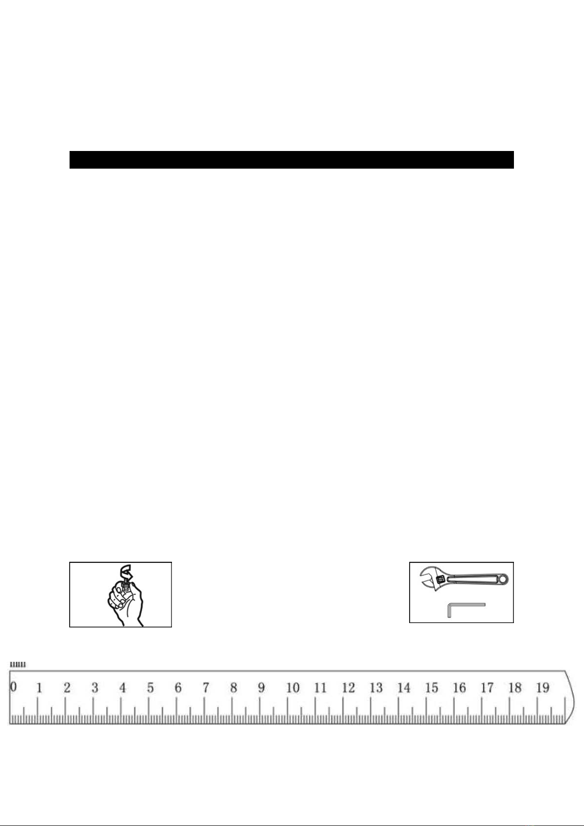
This drawing instructs
you to just screw the
bolts by hand, without
tightening.
This means to tighten all
screw and bolts rmly.
The ruler below can be used to count the dimensions of the bolts. Keep in mind
that the previous drawings are neither in scale nor in actual size.

— 4 —
PARTS LIST

— 5 —
PARTS LIST

— 6 —
PARTS LIST
Drawing # Pcs Description Drawing # Pcs Description
84 1 Μ10x150mm Allen Bolt
83 10 M10x85mm Carriage
Bolt
93 2 M8x40mm Allen Bolt 89 1 M10x30mm Allen Bolt
85 5 M10x85mm Allen Bolt
95 2 M8x22mm Allen Bolt 90 10 M10x20mm Allen Bolt
92 2 M8x85mm Allen Bolt
94 2 M8x18mm Allen Bolt 91 14 M10x16mm Allen Bolt
86 1 M10x68mm Allen Bolt
99 10 8 Washer 97 70 10 Washer
87 2 M10x65mm Allen Bolt
98 2 30x10,5 Washer 100 2 Μ8 Aircraft Nut
88 7 M10x50mm Allen Bolt
101 29 Μ10 Aircraft Nut 79 4 Clip Hook
1#5 Allen Wrench 2#6 Allen Wrench
81 1 10 Joint Chain
80 1 15 Joint Chain
78 1 M10x16x57mm Axle
77 1
M10x16x169mm Axle

— 7 —
ASSEMBLY INSTRUCTIONS
Step 1
1) Put the Guide Rod (5) through 2 x Rubber Bumpers (62) from bottom and then insert the Guide
Rod (5) into the Rear Base Frame (2) and secure with 2 x M10×20mm Allen Bolts (90) and 2 x
Ø10mm Washers (97). For details please refer to Diagrams B & C.
2) Connect the Base Frame (3), U-Shape Bracket (27) to the Rear Base Frame (3) using 2 x M10×85mm
Carriage Bolts (83), 2 x Ø10mm Washers (97) and 2 x M10 Aircraft Nuts (101). Please refer to Dia-
gram A.

— 8 —
Step 2
1) Connect the Base Frame (3), Bracket (29) to the Front Vertical Frame (1) using 2 x M10×85mm Car-
riage Bolts (83), 2 x Ø10mm Washers (97) and 2 x M10 Aircraft Nuts (101). Please refer to Diagram A.
2) Attach the Seat Support (9), Bracket (28) to the Front Vertical Frame (1) using 4 x M10×85mm Car-
riage Bolts (83), 4 x Ø10mm Washers (97) and 4 x M10 Aircraft Nuts (101). Please refer to Diagram B.

— 9 —
Step 3
1) Sequentially put the Guide Rod (5) through the 13 pieces Weight Plates (32) and the 1 piece Selec-
tor Stem (31), insert the Selector Rod (17) into the central hole, and then position the Foot Plate
(13) on it.
2) Uplift the front part of the base frame and assemble the Foot Plate (13) hole to hole, then insert the
Foot Plate Tube (23) to secure, enclose both ends with Ø25×1.5 End Caps (74). Refer to Diagram A.

— 10 —
Step 4
1) Connect the Upper Frame (4), Bracket (29) to the Front Vertical Frame (1) using 2 x M10×85mm
Carriage Bolts (83), 2 x Ø10mm Washers (97) and 2 x M10 Aircraft Nuts (101). Refer to Diagram A.
2) Connect the Upper Frame (4) to the Guide Rods (5) using 2 x M10×20mm Allen Bolts (90) and 2 x
Ø10mm Washers (97). Refer to Diagram B.

— 11 —
Step 5
1) Attach the Front Press Base (6) to the Upper Frame (4) using M10ר16×169 Axle (77), 2 x Ø10mm
Washers (97) and 2 x M10 Aircraft Nut (101). Refer to Diagram A.
2) Attach two Swivel Pulley Brackets (16) to both sides of the Front Vertical Frame (1) using 2 x
M10×65mm Allen Bolts (87), 4 x Ø10 Washers (97) and 2 x M10 Aircraft Nuts (101). Refer to Dia-
gram B.

— 12 —
Step 6
1) Inset the Backrest Adjustment Frame (12) into the FrontVertical Frame (1), and secure with M18×1.5
Lock Knob (48). Refer to Diagram A.
2) Then insert the Arm Curl Stand (11) into the Seat Support (9), and secure with M18×1.5 Lock Knob
(48). Refer to Diagram B.
3) Attach the Leg Developer (10) to the Seat Support (9) using 2 x M10×20mm Allen Bolts (90), 2 x
Ø10mm Washers (97) and 1 x M10ר16×57 Axle (78). Refer to Diagram B.

— 13 —
Step 7
1) Attach the L & R Buttery Adjustment Frame (18 & 19) and 2 x Buttery Axle Bushings (52) to both
sides of the Front Press Base (6), secure with 2 x M18 Lock Ring (56), 2 x M10×16mm Allen Bolts (91)
and 2 x Ø10mm Washers (97), for details please refer to Diagram A.
2) Insert the L & R Buttery (7 & 8) into the holes of the L & R Buttery Adjustment Frame (18 & 19),
and secure with 2 x Spacers (55), 2 x M10×20mm Allen Bolts (90) and 2 x Ø10mm Washers (97).
3) Turn two M18×1.5 Lock Knobs (49) to the L & R Buttery (7 & 8), and secure with 2 x M8×22 Allen
Bolts (95), 4 x Ø8mm Washers (99) and 2 x M8 Aircraft Nuts (100), refer to Diagram A.
4) Put the L & R Buttery (7 & 8) through the foam rolls, then insert two Front Press Handle (15) in-
to the holes on the L & R Buttery (7 & 8), and secure with 2 x M10×20mm Allen Bolts (90) and 2 x
Ø10mm Washers (97), refer to Diagram B.

— 14 —
Step 8
Notes: The pulley on the Front Press Base (6) should be enclosed by two Pulley Covers (60).
1) According to the cable diagram, sequentially use 6 x Pulleys (59), 4 x M10×85mm Allen Bolts (85),
1 x M10×150mm Allen Bolt (84), 1 x M10×50mm Allen Bolt (88), 12 x Ø10mm Washers (97), 2 x
Ø30ר 10.5mm Washers (98), 6 x M10 Aircraft Nuts (101) and 2 x Double Floating Pulley Bracket
(26) to connect Upper Cable (34), refer to Diagram 8-A.
2) Secure the Pulley (59) using 2 x Double Floating Pulley Brackets (26), 1 x M10×50mm Allen Bolt
(88), 2 x Ø10mm Washers (97), 1 x M10 Aircraft Nut (101), 2 x Cable Retainers (40) and 2 x Cable Re-
tainer Bushings (41), refer to Diagram 8-B.
3) Insert the Weight Selector Pin (33) into the hole of the selected weight plate, put the key ring on
the Selector Rod (17), and connect the end with thread head of the Upper Cable (34) to the Selec-
tor Rod (17), refer to Diagram 8-C.

— 15 —

— 16 —
Step 9
1) Sequentially use 1 x Angled Floating Pulley Bracket (14), 3 x Pulleys (59), 3 x M10×50mm Allen Bolts
(88), 6 x Ø10mm Washers (97) and 3 x M10 Aircraft Nuts (101) to connect the Buttery Cable (36),
and hang both ends of the cable on the hook of the L & R Buttery Adjustment Frame (18 & 19).
2) Attach 2 x Pulleys (59) to the left and right Swivel Pulley Bracket (16) using 2 x M10×50mm Allen
Bolts (88), 4 x Ø10mm Washers (97), 2 x M10 Aircraft Nuts (101), 4 x Cable Retainers (40) and 4 x Ca-
ble Retainer Bushings (41), refer to Diagram A.
3) Attach 1 x Pulley (59) to the top of the Angled Floating Pulley Bracket (14) using 1 x M10×50mm
Allen Bolt (88), 2 x Ø10mm Washers (97), 1 x M10 Aircraft Nut (101), 2 x Cable Retainers (40) and 2
x Cable Retainer Bushings (41), refer to Diagram B.

— 17 —
Step 10
1) Sequentially use 1 x Angled Floating Pulley
Bracket (14), 2 x Double Floating Pulley Brack-
ets (26), 5 x Pulleys (59), 3 x M10×50mm Al-
len Bolts (88), 1 x M10×68mm Allen Bolt (86),
1 x M10×85mm Allen Bolt (85), 10 x Ø10mm
Washers (97) and 5 x M10 Aircraft Nuts (101)
to connect the Lower Cable (35).
2) Put 1 x Pulley (59) in the groove of the Leg
Developer (10) as shown in the diagram, and
then secure with 1 x M10×68mm Allen Bolt
(86), 2 x Ø10mm Washers (97) and 1 x M10
Aircraft Nut (101), refer to Diagram 10-A.
3) Put 1 x Pulley (59) in the groove of the Leg De-
veloper (10), and secure with 1 x M10×85mm
Allen Bolt (85), 2 x Ø10mm Washers (97), 1 x
M10 Aircraft Nut (101), refer to Diagram 10-B.
4) Attach 1 x Pulley (59) to the U-shape pul-
ley support on the Base Frame (3) using 1 x
M10×50mm (88), 2 x Ø10mm Washers (97), 1
x M10 Aircraft Nut (101), 2 x Cable Retainers
40) and 2 x Cable Retainer Bushings (41),
refer to Diagram 10-B.
5) Connect the Lower Cable (35) to the U-
shaped bracket of the Base Frame (3) using
1 x M10×30mm Allen Bolt (89), 2 x Ø10mm
Washers (97) and 1 x M10 Aircraft Nut (101),
refer to Diagram 10-B.
6) Fix and secure 1 x Pulley (59) using 2 x
Double Floating Pulley Bracket (26), 1 x
M10×50mm Allen Bolt (88), 2 x Ø10mm
Washers (97), 1 x M10 Aircraft Nut (101), 2 x
Cable Retainers (40) and 2 x Cable Retainer
Bushings (41), refer to Diagram 10-C.
7) Fix 1 x pulley (59) to the bottom of the An-
gled Floating Pulley Bracket (14) using 1
x M10×50mm Allen Bolt (88), 2 x Ø10mm
Washers (97), 1 x M10 Aircraft Nut (101), 2 x
Cable Retainers (40) and 2 x Cable Retainer
Bushings (41), refer to Diagram 10-D.

— 18 —
Step 11
1) Attach the Seat Pad (37) to the Seat Support (9) using 2 x M8×85mm Allen Bolts (92) and 2 x Ø8mm
Washers (99).
2) Attach the Backrest Board (38) to the Front Vertical Frame (1) using 2 x M8×40mm Allen Bolts (93)
and 2 x Ø8mm Washers (99).
3) Attach the Arm Curl Pad (39) to the Arm Curl Stand (11) using 2 x M8×18mm Allen Bolts (94) and
2 x Ø8mm Washers (99).
4) Insert two Foam Roll Tubes (24) into the Seat Support (9) and Leg Developer (10) respectively, then
put 4 x Foam Rolls (46) through the two sides and enclose with 4 x Foam Roll End Caps (45).

— 19 —
Step 12
1) Fix the bottom of two Weight Stack Covers (25) to the Base Frame (3), Rear Base Frame (2) and
Bracket (30) using 6 x M10×16mm Allen Bolts (91) and 6 x Ø10mm Washers (97).
2) Then x the top of the two Weight Stack Covers (25) to the Upper Frame (4) and another Bracket
(30) using 6 x M10×16mm Allen Bolts (91) and 6 x Ø10mm Washers (97).
3) Secure all the bolts.

— 20 —
Step 13
1) Connect the Lat Bar (21) to the Upper Cable (34) using 1 x 10 Joint Chain (81) and 2 x Clip Hooks
(79), hang the Lat Bar (21) on the hook of the Upper Frame (4) when not using it to avoid injury.
2) Connect the Shiver Bar (22) to the Lower Cable (35) using1 x 15 Joint Chain (80) and 2 x Clip Hooks
(79), the Shiver Bar (22) is used for low pull and biceps exercises, when doing leg developing exer-
cise, it should be removed and replaced with the Ankle Strap (42).
This manual suits for next models
1
Table of contents
Other Amila Home Gym manuals