Amila DS915 User manual

Home Gym DS915
(code: 91201)
IN ORDER FOR THE WARRANTY TO BE VALID,
PLEASE, BEFORE YOU BEGIN
ASSEMBLING AND USING THE MACHINE,
READ THIS INSTRUCTIONS.
Assembly instructions & χρήσης

— 2 —
HOME GYM DS915 ASSEMBLY
INSTRUCTIONS # 91201
SAFETY INSTRUCTIONS
1. Read all instructions and perform warm up exercises before using this machine.
2. The home gym is a home tness instrument, as well as an aerobic tness instrument that can help
you develop your cardio-respiratory functions.
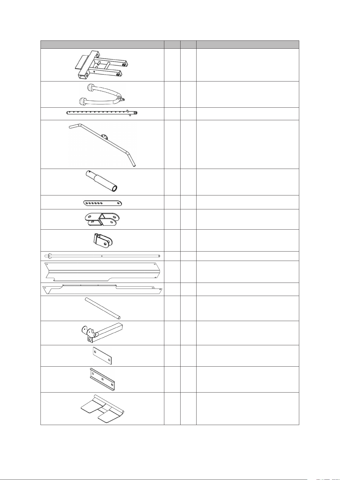
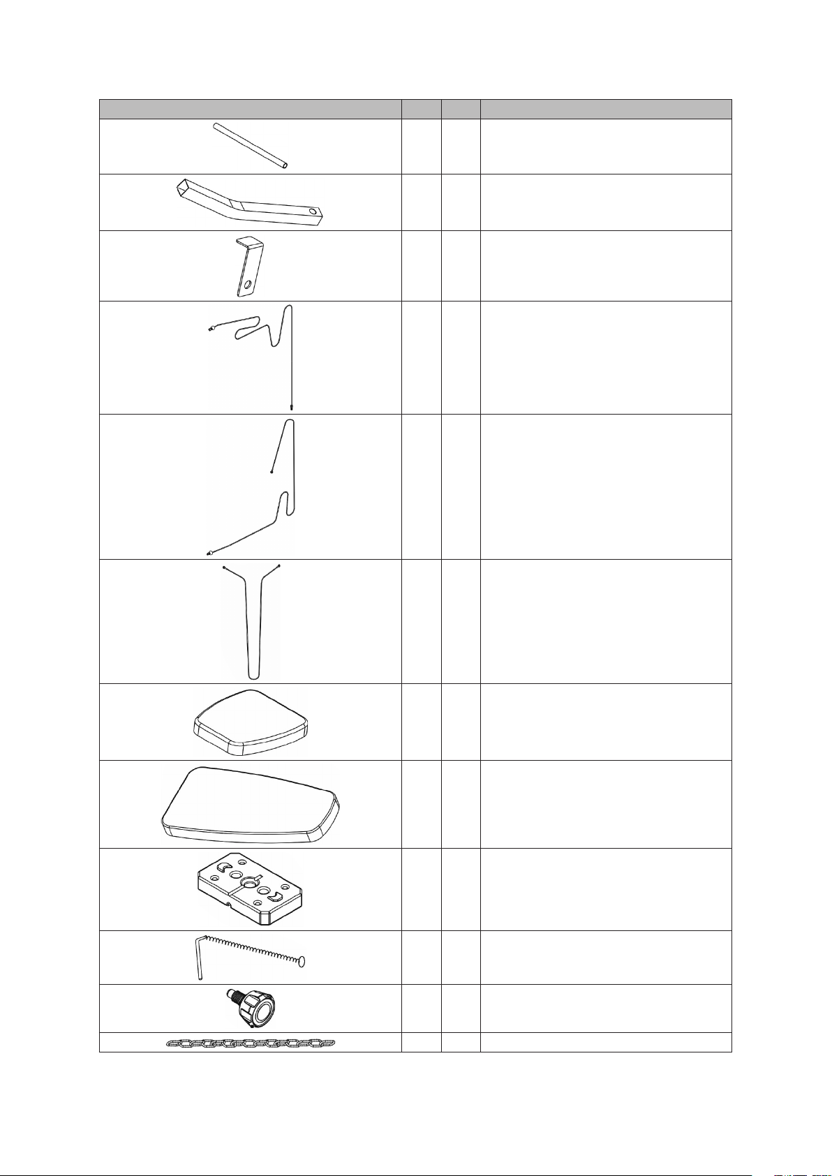
3. Check all components before assembly/use and make sure everything is correct and ready for use.
4. The home gym should be placed on a perfectly at surface and, as the surfaces are usually not at,
the use of a synthetic foam carpet or rug is recommended.
5. Consult your doctor about the level of eort you should reach. This is a must if you are over 45 years
of age or have a previous medical history.
6. For your exercise to be eective, it must be done on a daily basis and for at least 20 minutes.
7. Before exercising, it is advised, in order not to injure any muscle, to do a warm-up on certain muscles.
After the exercise you should also do some relaxation and stretching exercises.
8. Keep infants, young children and pets away from the home gym.
9. Keep your hands away from moving parts.
10. If the multi-instrument does not work properly, contact your supplier.
11. Do not use the product in an area where sprays, oxygen or other ammable materials/gases are
stored.
12. Do not place objects in the openings.
13. Do not use outdoors.
14. Do not use the product for any purpose other than that recommended.
15. Always wear sneakers.
16. Do not exercise an hour before eating / Do not eat an hour before exercising.
17. If you feel unwell, dizzy, nauseous or anything else, stop exercising immediately and consult a doctor.

— 3 —
COMPONENTS - PARTS
Drawing # PCS Description
1 1 Seat pad support
2 1 Rear stabilizer
3 1 Vertical tube
4 1 Top horizontal tube
5 1 Right buttery arm receptacle
6 1 Left buttery arm receptacle
7 1 Leg stretch tube
8 1 Base
9 1 Base for swivel pulley bracket
10 1 Front stabilizer

— 4 —
Drawing # PCS Description
11 1 Front press frame
12 1 Triceps rope
13 1 Weight selector rod
14 1 Long bar
15 2 Handles
16 2 Double oating pulley bracket
17 1 Cross double oating pulley bracket
18 2 Swivel pulley bracket
20 2 Guide rods
21 1 Right plate cover
22 1 Left plate cover
23 2 Foam roll axle
24 1 Leg stretch tube support
25 3 Small bracket
26 1 Large bracket
27 1 Leg press plate

— 5 —
Drawing # PCS Description
28 1 Leg press axle
29 2 Buttery arm
30 2 Retainer
31 1 Top cable, 3.530mm
32 1 Lower cable, 3.370mm
33 1 Buttery cable, 3.020mm
34 1 Seat pad
35 1 Back pad
37 15 Weight plates
38 1 Weight selector
39 3 Knob
43 1 Long chain

— 6 —
Drawing # PCS Description
44 1 Short chain
45 5 Hook
46 1 Knob
47 1 Safety pin
49 4 Foam roll caps
50 4 Small foam roll
51 2 Big foam roll
52 17 Pulleys
70 1 Small bar
73 30 End caps
74 1 Single grip
75 1 Ankle strap
76 2 Safety loops
101 2 Rubber rings
102 19 Retainer
103 19 Retainer bushing
104 2 Bushing

— 7 —
Drawing # Pcs Description Drawing # Pcs Description
41 1 Ø16 × 206 × M10 axle
53 1 Μ10 × 180 allen bolt
54 1 Μ10 × 110 allen bolt
63 2 Μ10 × 90 bolt
60 2 Μ8 × 85 allen bolt
64 6 Μ10 × 70 bolt
56 3 Μ10 × 65 allen bolt
61 14 Μ10 × 50 allen bolt
42 1 Ø16 × 57 × M12 axle
57 2 Μ10 × 45 allen bolt
36 1 Μ10 × 35 allen bolt 55 1 Μ10 × 28 allen bolt
58 8 Μ10 × 25 allen bolt 65 2 Μ12 × 20 allen bolt
62 6 Μ8 × 18 allen bolt 59 8 Μ10 × 16 allen bolt
66 4 Μ5 × 10 bolt 71 2 Ø12 washer
67 66 Ø10 washer 68 6 Ø8 washer
72 4 Μ5 aircraft nut 69 32 Μ10 aircraft nut

— 8 —
Drawing # Pcs Description Drawing # Pcs Description
— 1 #5 allen wrench
— 1 #6 allen wrench
— 2 #8 allen wrench
On the next pages you will see many numbered parts that were not mentioned previously.
All these parts are pre-installed from the factory and are included for the sole purpose to
be able to identify them if you need to order replacements.
This drawing instructs
you to just screw the
bolts by hand, without
tightening.
This means to tighten all
screw and bolts rmly.
The ruler below can be used to count the dimensions of the bolts. Keep in mind
that the previous drawings are neither in scale nor in actual size.

— 9 —
ASSEMBLY INSTRUCTIONS
Step 1
1) Place rubber rings (101) on the top of the guide rods (20) and push them all the way down.
2) Place the guide rods (20) in the holes of the rear stabilizer (2) and fasten them using allen bolts (58)
and washers (67).
3) Connect the base (8) to the rear stabilizer (2) using a large bracket (26), bolts (64), washers (67) and
nuts (69).
4) Connect the front stabilizer (10) to the base (8) using a small bracket (25), bolts (64), washers (67)
and nuts (69).
5) Insert the leg press axle (28) in the hole of the leg press plate (27). Then align the axle (28) with
the holes in the front part of the front stabilizer (10) and fasten it with bolts (58) and washers (67).

— 10 —
Step 2
Connect the vertical tube (3) to the base (8)
using small bracket (25), bolts (64), wash-
ers(67) and nuts (69).
Step 3
Then slide all but one of the weight plates (37) over
the guide rods (20), place the weight selector rod (13)
in the center hole of the weight plates (37) and then
place the remaining plate (37), making sure that all the
holes which are on the bottom of the plates are facing
to the front.

— 11 —
Step 4
Place the top horizontal tube (4) on the vertical tube (3) and the guide rods (20) and fasten it using
bolts (58) and washers (67) on its back, while at the connection with the vertical tube use a small
bracket (25), bolts (63), washers (67) and nuts (69).

— 12 —
Step 5
1) On the back of the vertical tube (3) fasten the base for swivel pulley bracket (9), using a bolt (54), 2
washers (69) and a nut (69). Then, at each side of the base (9) fasten swivel pulley brackets (18) us-
ing one bolt (56), 2 washers (67) and on nut (69) on each side.
2) Fasten the front press frame (11) to the top horizontal tube (4) using an axle (41), 2 washers (67)
and 2 nuts (69).
3) Attach the buttery arm receptacles (5 & 6) to the front press frame (11) using safety loops (76),
washers (67) and bolts (59).
4) Attach the buttery arms (29) to their receptacles (5 & 6) using knobs (39), adjusting them to the
desired height.
5) Push big foam rolls (51) on the buttery arms (29) and then attach handles (15), which you fasten
using washers (67) and bolts (58).

— 13 —
Step 6
1) Attach the seat pad support (1) to the vertical tube (3) using a knob (46) and safety pin (47).
2) Attach the leg stretch tube support (24) to the seat pad support (1) with a knob (39).
3) Attach the leg stretch tube (7) to its support (24) using an axle (42), 2 washers (71) and 2 bolts (65).

— 14 —
Step 7
1) Feed the bolt end of the upper cable (31) through the opening of the front end of the top hori-
zontal tube (4). Place a pulley (52) under the cable and fasten it with bolt (57), 2 washers (67) and
a nut (69) (Fig.“Α”).
2) Draw the cable backwards and place the second pulley (52), securing her with a bolt (61), nut (69),
2 washers (67), 2 retainers (102) and 2 retainer bushings (103) (Fig. “B”).
3) Draw the cable towards the front and place the third pulley (52), securing her with a bolt (53), 2
washers (67) and a nut (69) (Fig.“C”).
4) Draw the cable backwards and place the fourth pulley (52), securing her with a bolt (61), 2 wash-
ers (67), nut (69), a retainer (102) and a retainer bushing (103) (Fig. “D”).
5) Draw the cable downwards and place the fth pulley (52), securing her on a double oating pul-
ley bracket (16) with 2 retainers (102), 2 retainer bushings (103), bolt (61), 2 washers (67) and nut
(69) (Fig. “Ε”).
6) Draw the cable upwards and place 2 pulleys (52) on the back of the top horizontal tube (4), secur-
ing them with 2 bolts (61), 4 washers (67), 2 retainers (30) and 2 nuts (69) (Fig. “F“).
7) Finaly, draw the cable downwards and screw its end to the weight selector rod (13), after placing
the ring of the weight selector (38).

— 15 —
Step 8
1) Attach the ends of the buttery cable (33) to the hooks on the back of the buttery arm recepta-
cles (5 & 6).
2) Draw the cable backwards and place pulleys (52) on the swivel pulley brackets (18) using a bolt
(61), a nut (69), 2 washers (67), 2 retainers (102) and 2 retainer bushings per pulley (103) (Fig.“Α”).
3) Draw the cable downwards and place a pulley (52) on a cross double oating pulley bracket (17)
using a bolt (61), a nut (69), 2 washers (67), 2 retainers (102) ans 2 retainer bushings (103) (Fig.“Β”).

— 16 —
Step 9
1) Place the lower cable (32) in the front part of the base (8). Place a pulley (52) over the cable and se-
cure it with a bolt (61), 2 washers (67), nut (69), retainer (102) and retainer bushing (103) (Fig. “Α”).
2) Draw the cable backwards to the vertical tube (3) and place another pulley (52) under the cable
and secure it with a bolt (61), 2 washers (67), nut (69), retainer (102) and retainer bushing (103)
(Fig. “Β”).
3) Go upwards and place a third pulley (52) an the bottom part of the cross double oating pulley
bracket (see Step 8, g. Β) and secure it with a bolt (61), 2 washers (67), nut (69), 2 retainers (102)
and 2 retainer bushings (103) (Fig. “C”).

— 17 —
4) Next go downwards, towards the back of the base (8) and place a fourth pulley (52) at the recep-
tacle and secure it with a bolt (61), 2 washers (67), nut (69), 2 retainers (102) and 2 retainer bush-
ings (103) (Fig. “D”).
5) At “Step 7”, No. 5 (Fig. “Ε”) you placed a pulley which is left hanging. At the bottom of this pulley
you can secure another. There you are supposed to secure the fth pulley (52), with the cable run-
ning over it, and secure it with a bolt (61), 2 washers (67), nut (69), 2 retainers (102) and 2 retain-
er bushings (103) (Fig. “Ε”). NOTE: There are many holes where you can secure this pulley. Choose
the one that gives the proper tension to the cable. By changing holes you can adjust the tension
of the cables.
6) Go downwards, on the back side of the vertical tube (3) and place the 6th pulley (52), securing it
with a bolt (57), nut (69) and 2 washers (67) (Fig.“F”).
7) Draw the cable upwards and place a pulley (52) in the slot of the vertical tube (3), securing it with
a bolt (56), nut (69) and 2 washers (104) (Fig.“G”).
8) Finally, place a ball (93) on the cable, add hook (45) by means of a bolt (36), nut (69) and 2 washers
(67) and connect the tricep’s rope (12) (Fig.“H”).

— 18 —
Step 10
1) Secure the back pad (35) to the vertical tube (3) using bolts (60) and washers(68).
2) Secure the seat pad (34) on the sead pad support (1) using bolts (62) and washers (68).
3) Insert axles (23) in the holes of the leg stretch tube (7) and its support (24), push small foam rolls
(50) on the axles and place caps (49).

— 19 —
Step 11
1) Secure the plate covers (21 & 22) to the rear stabilizer (2), base (8) and top horizontal tube(4) using
6 bolts (59) and 6 washers (67).
2) Secure the plate covers (21 & 22) to each other with 4 bolts (66) and 5 nuts (72).

— 20 —
Step 12
1) Connect the short chain (44) to the lower cable (32) using a hook (45).
2) Connect the other end of the chain (44) to the leg stretch tube (7) using a bolt (55), 2 washers (67)
and a nut (69).
3) Place the long bar (14) on the hooks on the front of the top horizontal bar (4). In order to use the
bar, you must use a hook (45) to connect it to a chain and a second hook to connect to the cable.
This manual suits for next models
1
Table of contents
Other Amila Home Gym manuals