Amit RRAS-MCT/A User manual

rras-mcta_g_en_100
RRAS-MCT/A
IP phone set for rolling stock
Operation manual
Version 1.00

RRAS-MCT/A
rras-mcta_g_en_100 2/19
AMiT, spol. s r.o. does not provide any warranty concerning the contents of this
publication and reserves the right to change the documentation without obliga-
tion to inform any body or authority about it.
This document can be copied and redistributed under following conditions:
1. The whole text (all pages) must be copied without any changes.
2. All redistributed copies must retain the AMiT, spol. s r.o. copyright notice
and any other notices contained in the documentation.
3. This document must not be distributed for purpose making of profit.
The names of products and companies used herein can be trademarks or regis-
tered trademarks of their respective owners.
AMiT is a registered trademark
Copyright (c) 2011, AMiT, spol. s r. o.
Producer: AMiT, spol. s r. o.
Naskové 3/1100, 150 00 Praha
www.amit.cz

RRAS-MCT/A
3/19 rras-mcta_g_en_100
Contents History of revisions.........................................................................................4
Related documentation...................................................................................4
1. Introduction..........................................................................................5
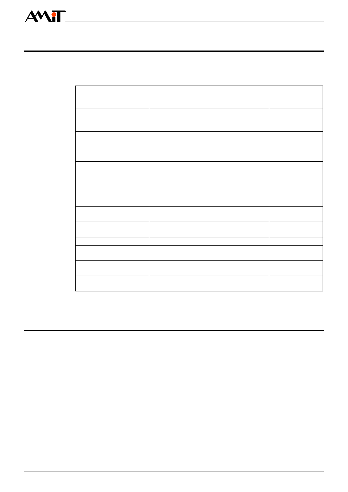
2. Technical parameters..........................................................................6
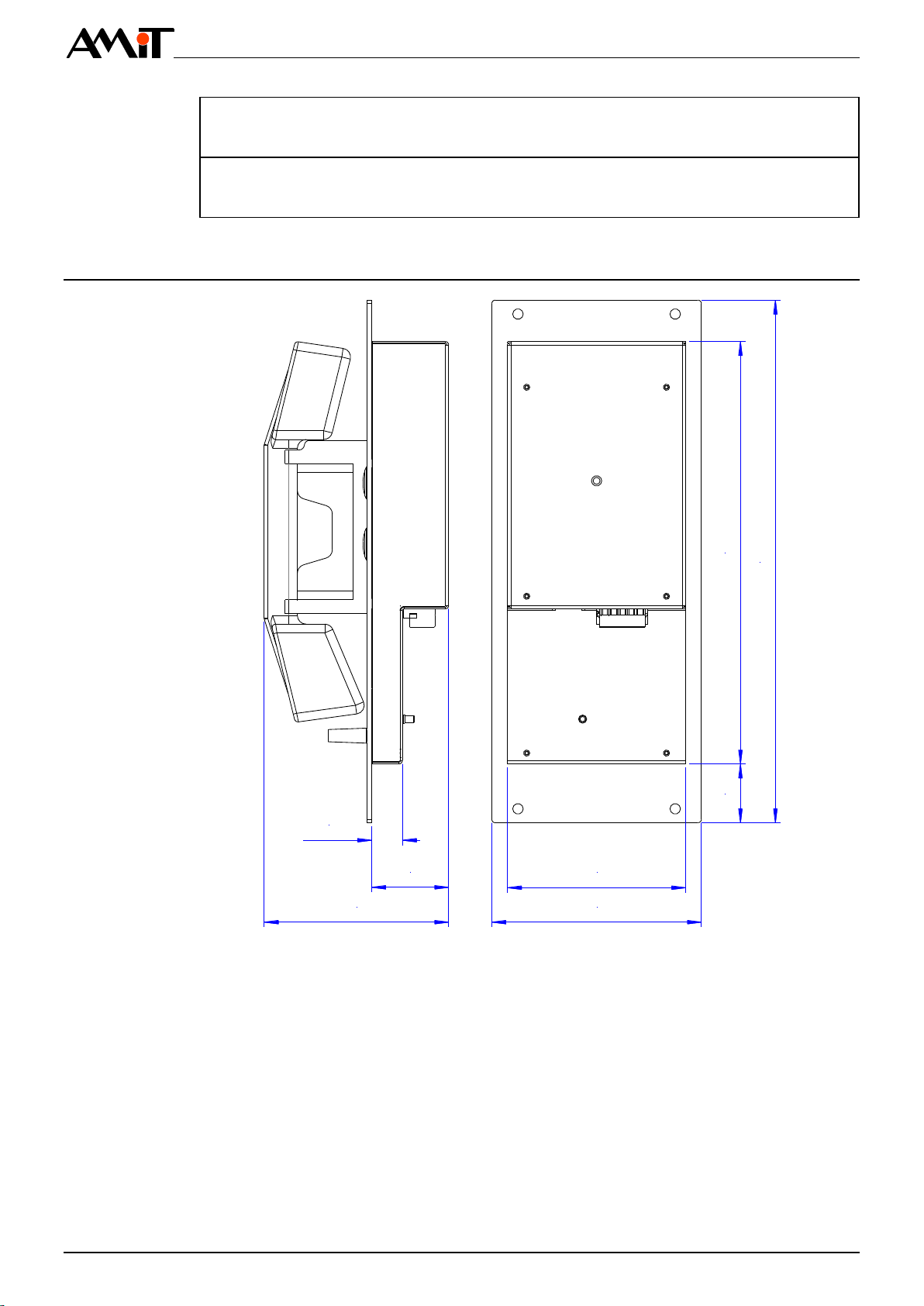
2.1. Dimensions.....................................................................................................7
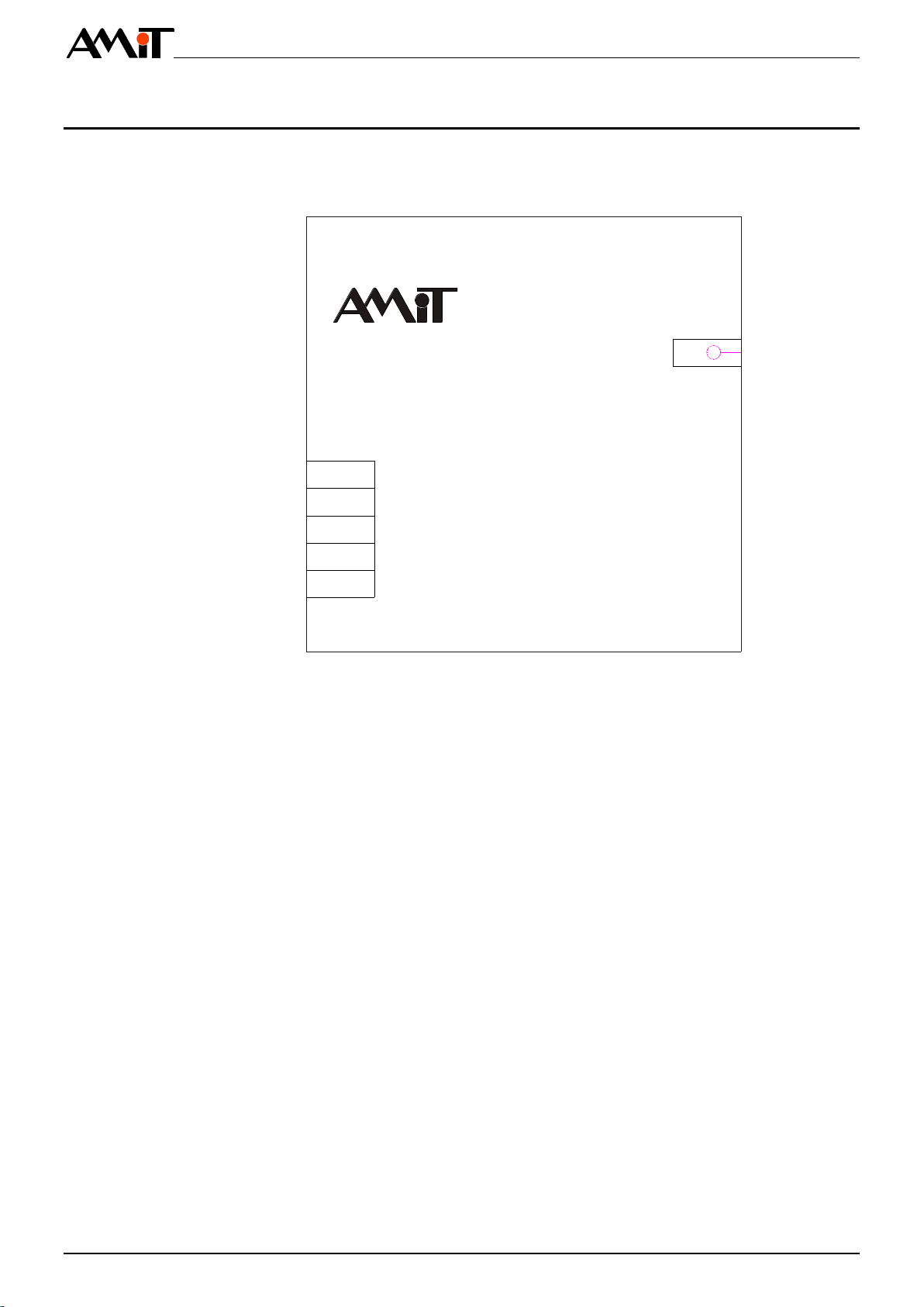
2.2. Recommended drawing symbol .....................................................................8
3. Compliance assessment.....................................................................9
3.1. Other tests......................................................................................................9
4. IP phone set front panel....................................................................10
4.1. Receiver handset..........................................................................................10
4.2. Buttons.........................................................................................................10
4.3. External audio input......................................................................................10
5. Power supply......................................................................................11
6. Speaker output...................................................................................12
7. Ethernet...............................................................................................13
8. Connectors and terminals layout.....................................................14
9. Configuration settings.......................................................................15
9.1. Factory settings............................................................................................15
10. Mounting.............................................................................................16
10.1. Installation rules............................................................................................16
11. Ordering information and completion .............................................17
11.1. Factory settings............................................................................................17
12. Maintenance .......................................................................................18
13. Waste disposal...................................................................................19

RRAS-MCT/A
rras-mcta_g_en_100 4/19
History of revisions
Document name: rras-mcta_g_en_100.pdf
Revision
Date
Changes
100
23. 5. 2011
New document
Related documentation
1. Operation manual ACASYS-AS
file: acasys-as_g_en_xx.pdf
2. Applicat
file: ap0016_en_xx.pdf

RRAS-MCT/A
5/19 rras-mcta_g_en_100
1. Introduction
RRAS-MCT/A is a communication device for rolling stock, determined for pas-
senger area.
Receiver handset with magnetic holder
2 illuminated control button
Attaching of external speaker for ringing and listening
Ethernet 100 Mbps interface
Panel mounting
Fig. 1 - RRAS-MCT/A IP phone set for rolling stock
Basic features

RRAS-MCT/A
rras-mcta_g_en_100 6/19
2. Technical parameters
Processor
STM32F207
Internal FLASH memory
512 KB
Internal RAM
128 KB
EEPROM
2 KB
Cable maximum length
100 cm
Handset fixation
Magnetic holder
Handset detection
Magnetic contact
Quantity
2
Type
Antivandal push button
Illumination
Green LED
Quantity
1
Characteristic impedance
Nominal power
Min. 5 W
Frequency range
250 Hz to 10 kHz
*) Speaker is not included
Connection point
RJ45 connector, according to IEEE802.3
Communication rate
100 Mbps
Galvanic separation strenght
300 V AC /1 minute *)
*) Insulation must not be used for dangerous voltage separation.
Power supply
%
Power consumption
Max. 200 mA at 24 V DC
Mechanical construction
Panel to be built into wall
Mounting
raised countersunk-head bolt
Ingress protection rate
IP30
Signal connection
WAGO 769 series connectors
Maximum wire cross section
2.5 mm2
Weight
1.8 kg
Dimen
Operating temperature range
-
Storage temperature range
-
Maximum ambient humidity
< 95 % non-condensing
Equipment is intended to operate up to 1 400 m above the sea level
Equipment is designed to meet the Temperature Class TX
According to EN 61373:1999 standard, the equipment is classified in terms of vibra-
tions into Category 1, Class A (mounting to vehicle body)
Permissible supplying voltage drop-outs duration: max 10 ms (Class S2 according to
Chapter 3.1.1.2 of EN 50155:2007).
For supply voltage switching are permissible conditions of C1 and C2 Class
CPU
Receiver
handset
Controls
Output for
speaker *)
Note:
Ethernet
Note:
Power supply
Mechanics
Temperatures
Others
Claims EN
50155:2007

RRAS-MCT/A
7/19 rras-mcta_g_en_100
The equipment meets the SWSIL0 classification according to EN 50128:2001 Rail-
way applications Communications, signalling and processing systems Software
for railway control and protection systems.
The equipment meets the SIL0 classification according to EN 50129:2003 Railway
applications Communication, signalling and processing systems Safety-related
electronic systems for signalling.
2.1. Dimensions
120
44,1
105,6
17,6
33,7 242,5
300
102
Fig. 2 - RRAS-MCT/A dimensions
Safety
classification

RRAS-MCT/A
rras-mcta_g_en_100 8/19
2.2. Recommended drawing symbol
Following drawing symbol is recommended for RRAS-MCT/A IP phone set. On-
ly part of it will be visible in following examples.
PWR
RRAS-MTC/A
X1
X2
SPK+
SPK-
+U
-U
CHS
3
4
5
1
2
ETH
RJ45
Fig. 3 - Recommended drawing symbol for RRAS-MCT/A

RRAS-MCT/A
9/19 rras-mcta_g_en_100
3. Compliance assessment
The equipment meets the claims of Czech government decree NV616/2006; the
compliance assessment has been performed in accordance with harmonized
standard EN 50121-3-2:2006.
Tested in accordance
with standard
Type of test
Classification
EN 55011:2007
Radio disturbance
complies
EN 61000-3-3:2008
EMC Limitations of voltage changes,
voltage fluctuations and flicker in public
low-voltage supply systems
complies
EN 61000-4-3:2006
EMC Part 4-3: Radiated, radio-
frequency, electromagnetic field
immunity test,
800 MHz to 1000 MHz
20 V/m
EN 61000-4-3:2006
EMC Part 4-3: Radiated, radio-
frequency, electromagnetic field
immunity test, 1000 MHz to 2100 MHz
10 V/m
EN 61000-4-3:2006
EMC Part 4-3: Radiated, radio-
frequency, electromagnetic field
immunity test, 2100 MHz to 2500 MHz
5 V/m
EN 61000-4-4:2004
Electrical fast transient/burst immunity
test power supply
4 kV *)
EN 61000-4-4:2004
EMC Electrical fast transient immunity
test inputs
2 kV *)
EN 61000-4-5:2006
EMC Surge immunity test, RS485
4 kV *)
EN 61000-4-5:2006
EMC Surge immunity test, power
supply
4 kV *)
EN 61000-4-6:2009
Immunity to induced disturbances,
induced by radio-frequency fields
10 V
EN 61000-4-11:2004
Voltage dips, short interruptions and
voltage variations immunity tests
complies
*) Some disturbing noise can be heard in the speaker when disturbances
appear.
3.1. Other tests
This product has been assessed and approved for use in railway applications
according to standards:
EN 50155:2007 Elecronic equipment used on rolling stock.
EN 50121-3-2:2006 Railway applications Electromagnetic compatibil-
ity Part 3-2: Rolling stock Apparatus
EN 61373:1999 Railway applications Rolling stock equipment
Shock and vibration tests.
EN 60068-2-1:2007 Environmental testing Part 2-1: Test A: Cold.
EN 60068-2-2:2007 Environmental testing Part 2-2: Test B: Dry heat.

RRAS-MCT/A
rras-mcta_g_en_100 10/19
4. IP phone set front panel
On the device front panel is located the handset with holder, control buttons and
3.5 mm jack for external sound source:
External audio input
Saloon message button
Cabin call button
Fig. 4 - IP phone set front panel
4.1. Receiver handset
Receiver handset is placed in magnetic holder. Device is activated by picking
up the handset. Speaker volume and microphone sensitivity are adjustable
through Ethernet interface.
4.2. Buttons
The buttons are used for calling to other IP phones and reporting to saloon.
They are backlighted by green LED operation indicators.
4.3. External audio input
An external audio signal can be connected through 3.5 mm jack to the device
input socket. After connector plug-in a message is sent to saloon via Ethernet
network. External input sensitivity is adjustable through Ethernet.

RRAS-MCT/A
11/19 rras-mcta_g_en_100
5. Power supply
The RRAS-MCT/A IP phone set can be powered by 24 V DC vehicle onboard
network.
Power supply
Fig. 5 - Power supply connector location
24 V=
PWR
RRAS-MTC/A
X1
X2
SPK+
SPK-
+U
-U
CHS
3
4
5
1
2
ETH
RJ45
Fig. 6 - IP phone set powering
Terminal
Label
Meaning
1
CHS
Module chassis.
2
-U
Power supply, ground
3
+U
Power supply, +24 V DC
The CHS terminal must be connected with vehicle frame.
Wiring
example
Wiring of X1
connector
(power supply
only)
Note:

RRAS-MCT/A
rras-mcta_g_en_100 12/19
6. Speaker output
Speaker connection
Fig. 7 - Location of connector for external speaker
Terminal
Label
Meaning
1
CHS
Module chassis.
2
-U
Power supply, ground
3
+U
Power supply, +24 V DC
4
SPK-
Cabin speaker
5
SPK+
Cabin speaker
Reproduktor
FR8WP8OHM (8
/15W)
+
-
PWR
RRAS-MTC/A
X1
X2
SPK+
SPK-
+U
-U
CHS
3
4
5
1
2
ETH
RJ45
Fig. 8 - Connection of additional speaker
Wiring of X1
connector

RRAS-MCT/A
13/19 rras-mcta_g_en_100
7. Ethernet
The Ethernet interface connector is located on IP phone set housing rear side.
LED indicators are built in Ethernet connector body.
Ethernet
Fig. 9 - Location of Ethernet line connector
Activity of Ethernet line is indicated by LEDs (LNK and ACT) on Ethernet line
connector. The LNK LED indicates attaching of Ethernet network cable, while
ACT LED indicates transmitting or receiving of data.
More details about Ethernet networking can be found in Application Note
AP0037.
Line state
indicator
Note:

RRAS-MCT/A
rras-mcta_g_en_100 14/19
8. Connectors and terminals layout
Power supply
Ethernet
Fig. 10 - Connectors and terminals layout

RRAS-MCT/A
15/19 rras-mcta_g_en_100
9. Configuration settings
All IP phone set configuration is performed via Ethernet interface.
9.1. Factory settings
The IP
button should be pressed while switching the phone set supply voltage on.
Successful factory restoring is indicated by short blinking of backlighted buttons
on panel front side.
Ehousing rear side.
Factory setting
Fig. 11 - Location of factory setting button

RRAS-MCT/A
rras-mcta_g_en_100 16/19
10. Mounting
RRAS-MCT/A IP phone set is designed to be mounted into wall in passenger
area. Phone set is vertically oriented.
9,0
108,0
90,0
250,0
284,0
22,0
Fig. 12 - Mounting aperture and holes for RRAS-MCT/A
Fasten the IP phone set by 4 bolts M6 with raised countersung head, according
to DIN 966. Size of mounting holes in wall must correspond to wall material and
used bolts.
10.1. Installation rules
Technical parameters of phone unit are guaranteed only when these wiring
principles are applied.
Connect the CHS terminal of X1 connector to the vehicle frame with as low as
possible impedance.
Unshielded UTP patch cable can be used for service or when utilized within
the switchboard frame. Apply the STP cabling for permanent use outside the
switchboard frame.
Fixing
Earthing
Ethernet
interface

RRAS-MCT/A
17/19 rras-mcta_g_en_100
11. Ordering information and completion
RRAS-MCT/A
Phone set for rolling stock, full WAGO connector set, Operation
manual, Warranty card
FR8WP8OHM/B
Speaker 8 ohm, black color
FR8WP8OHM/W
Speaker 8 ohm, white color
FR8WP TES
Gasket for FR8WP
11.1. Factory settings
Phone set default IP address is: 192.168.1.1
Phone set
Speaker

RRAS-MCT/A
rras-mcta_g_en_100 18/19
12. Maintenance
The maintenance mentioned above can be performed by manufacturer or
authorized service only.
Time after time, with regard to way of using it is necessary to remove dust from
device. The equipment can be cleaned by dry soft brush or vacuum cleaner,
only when turned-off and disassembled.
Clean the stainless front panel by current cleaning agent, recommended for
stainless material. When cleaning, be sure, that water does not flow to speaker
and microphone through perforation in handset body.
Warning
Cleaning
Front panel

RRAS-MCT/A
19/19 rras-mcta_g_en_100
13. Waste disposal
The disposal of electronic equipment is subject to the regulations on handling
electrical waste. The equipment must not be disposed off in common public
waste. It must be delivered to places specified for that purpose and recycled.
Electronics
disposal
Table of contents