Stentofon A100K10788 User manual
TECHNICAL MANUAL A100K10788
INSTALLATION & CONFIGURATION GUIDE
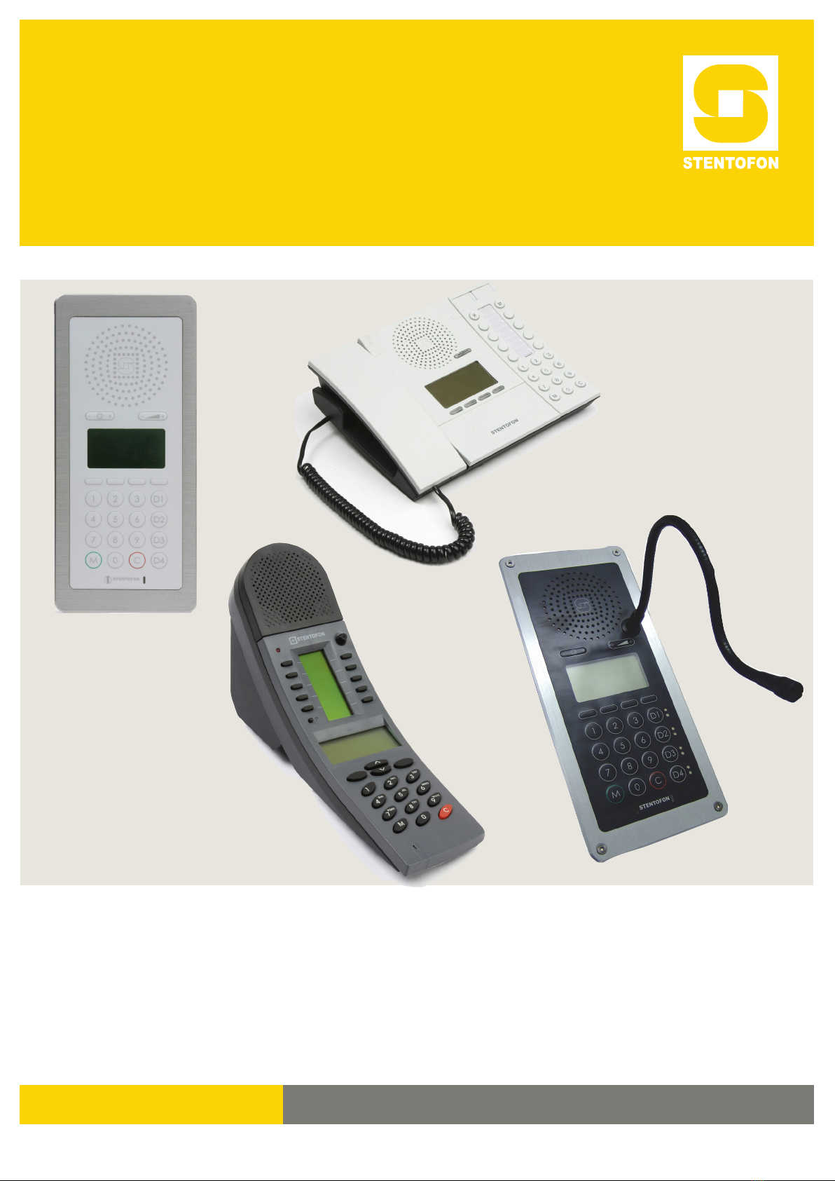
IP Master Stations

Zenitel Norway AS and its subsidiaries assume no responsibilities for any errors that may appear in this
publication, or for damages arising from the information in it. No information in this publication should be
regarded as a warranty made by Zenitel Norway AS.
The information in this publication may be revised or changed without notice. Product names mentioned in
this publication may be trademarks of others and are used only for identication.
Zenitel Norway AS © 2010
About this Document
Document Scope
This document describes the installation and conguration of the various models
of the STENTOFON IP Master Station range including accessories such as the
IP DAK-48 unit, gooseneck microphone and handset.
Revision Information
Rev. Date Author Status/Comments
1.0 3 Feb 2010 HKL Published
1.1 6 April 2010 HKL Revised gooseneck mic
illustration & instructions
1.2 22 Sept 2010 ER New dimension drawing IP Flush
2.0 17 Dec 2010 HKL New display/screenshots & XE
2.1 12 May 2011 HKL
IP Dual Display station.
Supersedes analog dual display
manual.
2.2 20 Dec 2011 HKL Screenshots for new station SW
Related Documentation
For further information, refer to the following documentation:
Doc. no. Documentation
A100K10805 AlphaCom XE Installation & Conguration Manual
A100K10760 IP DAK-48 Unit Installation Guide
A100K10602 AlphaCom User Guide

3
IP Master Station Installation & Conguration
A100K10788
Contents
1 Introduction.................................................................................................................................... 5
1.1 Features Overview .................................................................................................................. 5
1.2 IP Desktop Master Station ...................................................................................................... 6
1.3 IP OR Master Station .............................................................................................................. 6
1.4 IP Flush Master Station ........................................................................................................... 7
1.5 IP DAK-48 Unit ........................................................................................................................ 7
1.6 IP Dual Display Station ........................................................................................................... 8
1.7 IP Master Station Kit ............................................................................................................... 8
2 Installation...................................................................................................................................... 9
2.1 Introduction ............................................................................................................................. 9
2.2 Power Supply .......................................................................................................................... 9
2.3 Network Connection ................................................................................................................ 9
2.4 Handset ................................................................................................................................. 10
2.5 Headset ..................................................................................................................................11
2.6 Gooseneck Microphone for IP Flush Master ......................................................................... 12
2.7 Gooseneck Microphone for IP Dual Display ......................................................................... 13
2.8 Input/Output Connections ..................................................................................................... 13
2.9 IP DAK-48 Unit ...................................................................................................................... 14
3 Conguration ............................................................................................................................... 15
3.1 Conguration Via Station Keypad ......................................................................................... 15
3.2 Conguration Via Web Browser ............................................................................................ 16
3.2.1 IP Master Station Web Interface ................................................................................ 16
3.2.2 Station Main Settings ................................................................................................. 17
3.3 Advanced Conguration Options .......................................................................................... 18
3.3.1 Noise Reduction .......................................................................................................... 18
3.3.2 VLAN ........................................................................................................................... 18
3.3.3 Network Access Control .............................................................................................. 20
4 SoftwareUpgrade ........................................................................................................................ 22
4.1 Prerequisites ......................................................................................................................... 22
4.2 Upgrade Via Station Web Server .......................................................................................... 22
4.3 Upgrade Via AlphaCom XE ................................................................................................... 23
A: Station Board Connections ........................................................................................................ 24
B: Station Indication LEDs .............................................................................................................. 27
B.1 Station LED ........................................................................................................................... 27
B.2 Status LED ............................................................................................................................ 27
B.3 Power LED ............................................................................................................................ 28
B.4 LAN LEDs ............................................................................................................................. 28
C: Dimensions&MountingInstructions ........................................................................................ 29
C.1 IP Desktop Master Station with Handset ............................................................................... 29
C.2 IP Desktop Master (Handset) Wall Mounting ........................................................................ 29
C.3 IP Desktop Master Station .................................................................................................... 30
C.4 IP Desktop Master Wall Mounting ......................................................................................... 30
C.5 IP Flush Master Station ......................................................................................................... 31
C.6 IP Flush Master Station and Handset Backboxes ................................................................. 31
C.7 IP OR Master Station ............................................................................................................ 32
C.8 Mounting & Demounting the IP OR Station ........................................................................... 32
C.9 IP Dual Display Station ......................................................................................................... 33
C.10 IP Master Station Kit ............................................................................................................. 34
D: RestoringFactoryDefaults......................................................................................................... 35
E: Station&AccessorySpecications........................................................................................... 36
E.1 IP Desktop Master (with & without Handset) ......................................................................... 36
E.2 IP OR Master Station ............................................................................................................ 36
E.3 IP Flush Master Station ......................................................................................................... 37
E.4 IP DAK-48 Unit ...................................................................................................................... 37
E.5 IP Dual Display Station ......................................................................................................... 38
E.6 IP Master Station Kit ............................................................................................................. 38
F: UserQuickReference ................................................................................................................. 39

4A100K10788
IP Master Station Installation & Conguration
Figures
Figure 1 STENTOFON Security and Communication System ............................................................ 5
Figure 2 IP Desktop Master Station Keys & Functions ....................................................................... 6
Figure 3 IP Flush/OR Master Station Keys & Functions ..................................................................... 7
Figure 4 IP Dual Display Station Keys & Functions ............................................................................ 8
Figure 5 RJ45 Ports at Rear of IP Desktop Master Station ................................................................ 9
Figure 6 RJ45 Port at Bottom of IP Dual Display Station .................................................................... 9
Figure 7 RJ45 Ports on IP Flush/OR Master Stations ........................................................................ 9
Figure 8 Installing the Handset ......................................................................................................... 10
Figure 9 Installing the Headset ..........................................................................................................11
Figure 10 Installing the Gooseneck Microphone for Flush Master...................................................... 12
Figure 11 Installing the Gooseneck Microphone for Dual Display ...................................................... 13
Figure 12 Installing the IP DAK-48 Unit .............................................................................................. 14
Figure 13 LAN Port on IP Flush/OR Master Stations .......................................................................... 16
Figure 14 LAN Port on IP Desktop Master Station ............................................................................. 16
Figure 15 Station Board Connections ................................................................................................. 24
Figure 16 IP Desktop Master with handset - Dimensions ................................................................... 29
Figure 17 IP Desktop Master (handset) Wall Mounting ...................................................................... 29
Figure 18 IP Desktop Master - Dimensions ........................................................................................ 30
Figure 19 IP Desktop Master Wall Mounting....................................................................................... 30
Figure 20 IP Flush Master - Dimensions ............................................................................................. 31
Figure 21 IP Flush Master - Backboxes .............................................................................................. 31
Figure 22 Flush Mount Backbox for IP OR Master Station ................................................................. 32
Figure 23 Mounting the IP OR Master Station .................................................................................... 32
Figure 24 Demounting the IP OR Master Station ............................................................................... 33
Figure 25 IP Dual Display Station - Dimensions ................................................................................. 33
Figure 26 IP Master Station Kit PCB Dimensions ............................................................................... 34
Tables
Table 1 Station Features ................................................................................................................... 5
Table 2 Station Connectors ............................................................................................................... 9
Table 3 Station Dimensions ............................................................................................................. 29

5
IP Master Station Installation & Conguration
A100K10788
1 Introduction
The STENTOFON IP Master Stations are connected to the AlphaCom
XE server/exchange which is the heart of the STENTOFON security and
communication system. The communication between the AlphaCom XE
exchange and the IP Master Stations utilize the STENTOFON CCoIP®
protocols. The CCoIP protocols allow for a wide set of call modes and
services that provide the ideal solution to your critical communication
requirements.
The AlphaCom XE exchange includes all main service congurations for
the IP stations and only a minimum conguration is needed to be carried
out on the actual station. For further details, see A100K10805 AlphaCom
XE Installation & Conguration Manual.
Figure 1 STENTOFON Security and Communication System
1.1 FeaturesOverview
The table below shows the available features of the IP Master Stations.
IP Desktop
w/ handset
IP Desktop IP Flush IP OR IP Dual
Display
Station Kit
Managed data switch YES YES YES YES YES YES
PoE (802.af) YES YES YES YES YES YES
Inline power YES YES YES YES YES YES
Local power NO NO YES YES NO YES
Relay output NO NO YES YES NO YES
Digital input NO NO YES YES NO YES
Display YES YES YES YES YES OPTION
Handset YES NO OPTION NO NO OPTION
Gooseneck microphone NO NO OPTION NO OPTION OPTION
Headset NO NO OPTION NO NO OPTION
IP DAK-48 unit NO NO OPTION NO NO OPTION
Table 1 Station Features
IPNetwork
AlphaCom XE Server/Exchange
IP Dual Display
IP OR Master
IP Desk Master
IP Flush Master
with Gooseneck
Microphone,
Handset, and
DAK-48 Unit
AlphaC om XE7

6A100K10788
IP Master Station Installation & Conguration
1.2 IPDesktopMasterStation
● item nos. 1008001000 (with handset), 1008000000 (without handset)
The IP Desktop Master is a general purpose intercom station featuring
a large high contrast display with backlight showing crystal clear
information. Ten direct access keys (DAK) provide single-touch access to
other stations, group calls, audio monitoring, public address zones, radio
channels and/or the opening of doors and gates.
The station connects directly to the IP network, making it easy to deploy
anywhere at any distance. The built-in web server allows monitoring,
conguration and software updates over the IP network for easy
maintenance of remote stations.
Figure 2 IP Desktop Master Station Keys & Functions
1.3 IPORMasterStation
● item no. 1008015000
The IP Operating Room (OR) Master Station is an advanced intercom
station intended for use in operating theatres and clean rooms. The
chemical resistant and anti-bacterial front plate is completely at and
sealed to minimize bacteria accumulation. The station has an excellent
audio quality. With a large backlit display and STENTOFON audio
technology, the station allows users to read caller ID, listen and talk at a
distance.
Menu Selection Buttons
Information Display
Loudspeaker
Indicator LED &
Volume Control
Cancel/Private
Direct Access Keys
(DAKs)
Dialing Keys
Manual Speech
Direction Control
Handset
Microphone

7
IP Master Station Installation & Conguration
A100K10788
1.4 IPFlushMasterStation
● item no. 1008031000
The IP Flush Master is intended for use in control and guard rooms.
The station features a large high contrast display with backlight and up
to 8 lines with 20 characters. The IP station has advanced call handling
features such as call queuing. The call queue is presented to the user
according to priority and time of arrival. The user can select which call to
answer by scrolling through the queue. Four direct access keys (DAK)
provide single-touch access to stations, group calls, audio monitoring,
public address zones, radio channels, and opening of doors and gates.
Each DAK key has a red and green LED to show the status.
Figure 3 IP Flush/OR Master Station Keys & Functions
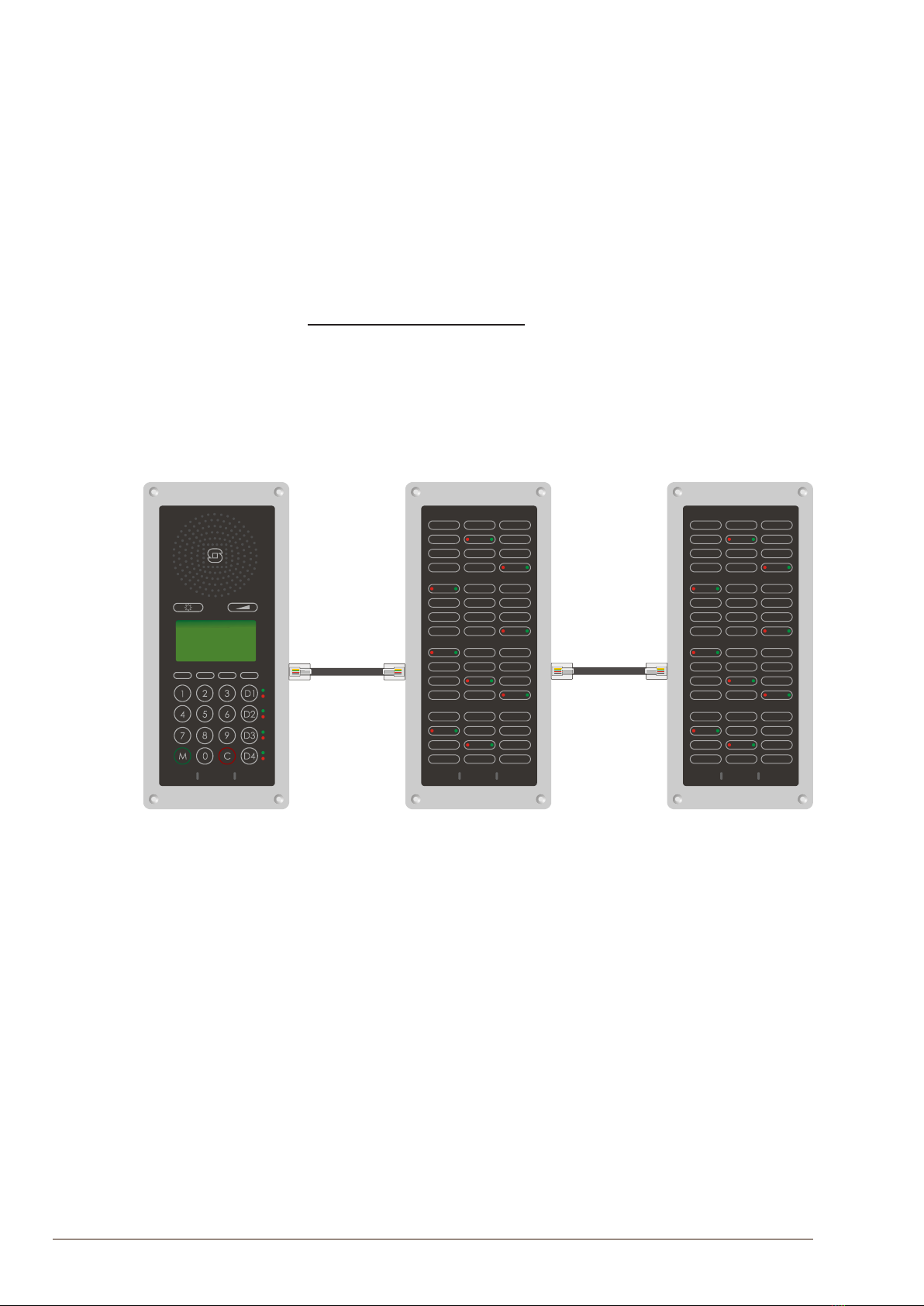
1.5 IP DAK-48 Unit
● item no. 1008010100
The IP DAK-48 Unit extends the IP Flush Master Station with DAK
buttons and visual indicators (LEDs), providing the ideal solution for
the control room. Each DAK key is equipped with two programmable
LED indicators, one red and one green. The LEDs can be used to show
alarms, notications, call requests, or any other indication required
from the system. This opens up for a wide range of integrations and
applications such as:
● Advanced call request handling with visual indications
● CCTV and intercom integration
● Dynamic group call and PA zone selection
● Simplex (radio) conference with visual indications
1
4
7
M
2
5
8
0
3
6
9
C
D1
D2
D3
D4
--
++
STENTOFON
Menu Selection Buttons
Information Display
Loudspeaker
Volume Control
Cancel/Private
Direct Access Keys (DAKs)
with LEDsIndicator
Dialing Keys
Manual Speech
Direction Control
Microphone
Indicator LED
Display Backlight Control

8A100K10788
IP Master Station Installation & Conguration
1.6 IP Dual Display Station
● item no. 1008007000
The IP Dual Display Station is designed for desktop installation in
banking/nancial and ofce environments. It is also well suited as a
control room station. The physical size makes it easy to place on desks
with limited space. An optional noise cancelling gooseneck microphone
module can be mounted in noisy environments. The dual backlit easy-
to-read displays and navigation buttons provide single-touch access
to stations, group calls, audio monitoring, public address zones, radio
channels, opening of doors and gates as well as other functions. The
direct access keys are easily programmed from the station and can be
changed at any time.
Figure 4 IP Dual Display Station Keys & Functions
1.7 IP Master Station Kit
● item no. 1008093000
The IP Master Station Kit features the printed circuit board (PCB) as used
in IP master stations. It is designed to produce custom IP stations to the
highest specications and for use in the harshest of environments. The IP
Master Station Kit provides up to 1.5 W audio output. If even higher audio
output is required, an external power amplier may be used. As a special
function, the PCB can extract power from the Ethernet’s PoE circuit and
provide up to 6 W power to external units. This means that the PCB can
power an external power amplier using its own PoE.
Privacy Button
Loudspeaker
Volume Control
Cancel
Direct Access Keys
(DAKs)
Dialing keys
Manual Speech Direction Control
Microphone
Indicator LED
Menu Selection Keys
Information Display
DAK DisplayInformation
Arrow Keys
9
IP Master Station Installation & Conguration
A100K10788
2 Installation
2.1 Introduction
The table below is an overview of the main connectors involved when
installing the STENTOFON IP Master Stations.
LAN 10/100 Mbps RJ-45 port for LAN (uplink) connection. Supports PoE
(802.3af). Draws power from either spare line or signal line.
AUX 10/100 Mbps RJ-45 ports for auxiliary equipment such as PC and IP
camera.
Handset Port RJ11 (only for IP Flush Master Station and IP Master Kit)
Headset Port RJ11 (only for IP Flush Master Station and IP Master Kit)
Input/Output Pluggable screw terminal (all stations except IP Desktop Station)
Extension Unit (IP DAK-48) RJ45 (only for IP Flush Master Station and IP Master Kit)
Local Power Plugable screw terminal, 17-27 VDC Idle 4W, max. 8W (all stations
except IP Desktop Station)
Table 2 Station Connectors
2.2 Power Supply
The IP Master Station supports Power over Ethernet (PoE, IEEE 802.3
a-f) where power can be drawn from either the spare line or signal line.
If PoE is not available, the IP Master Station (except for IP Desktop) can
be connected to a 24 VDC local power supply. See Appendix A: Station
Board Connections for local power supply connections.
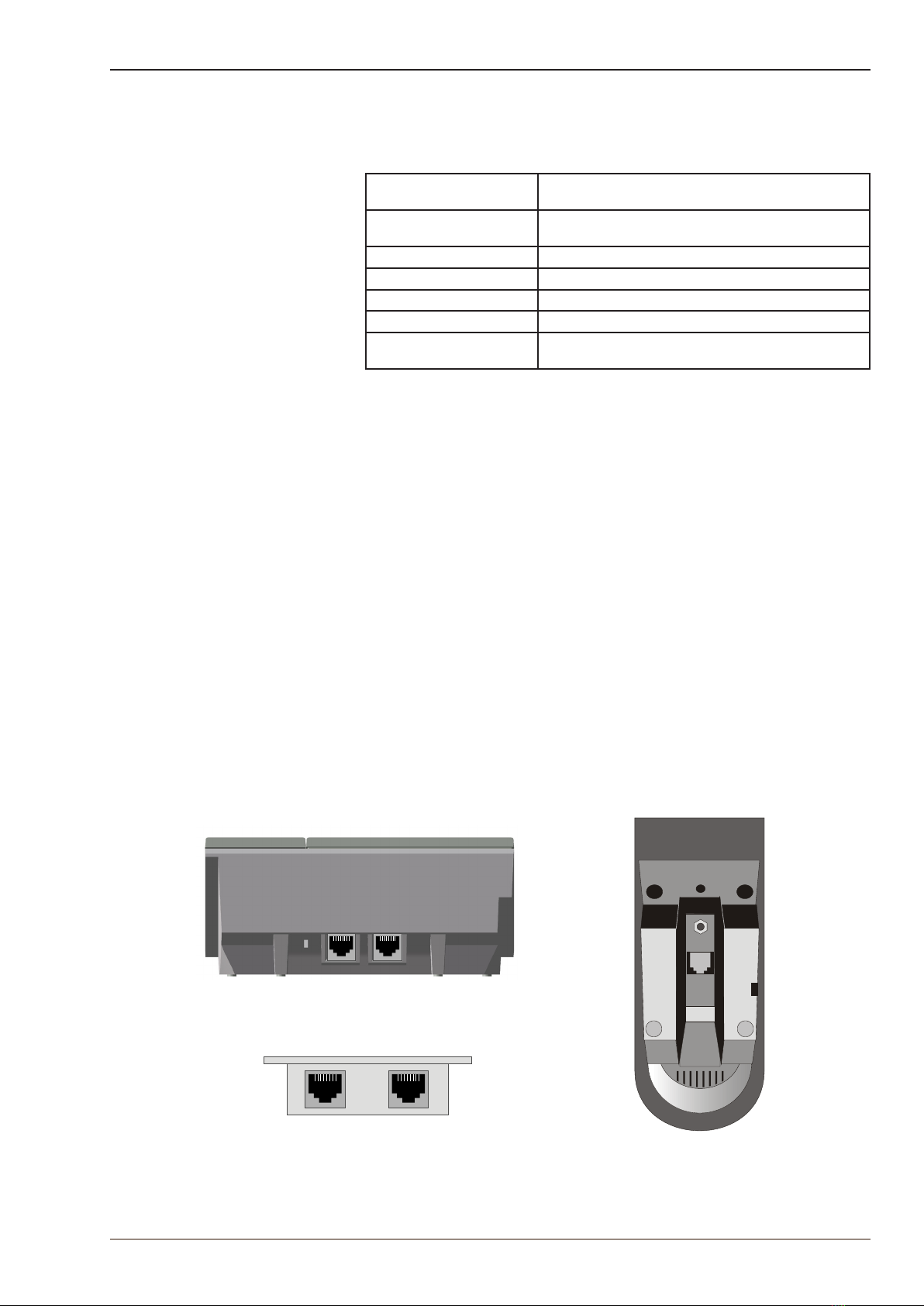
2.3 NetworkConnection
There are two RJ45 ports on the IP Master stations:
● LAN port is for connecting to the network and the AlphaCom XE
exchange.
● AUX port is for connecting to auxiliary equipment such as a PC.
There is one RJ45 port located at the bottom of the IP Dual Display
station that is used as the LAN port.
Figure 5 RJ45 Ports at Rear of IP Desktop
Master Station
RJ45
Figure 6 RJ45 Port at Bottom of IP Dual
Display Station
Figure 7 RJ45 Ports on IP Flush/OR Master
Stations
LAN
AUX
LAN
AUX
10 A100K10788
IP Master Station Installation & Conguration
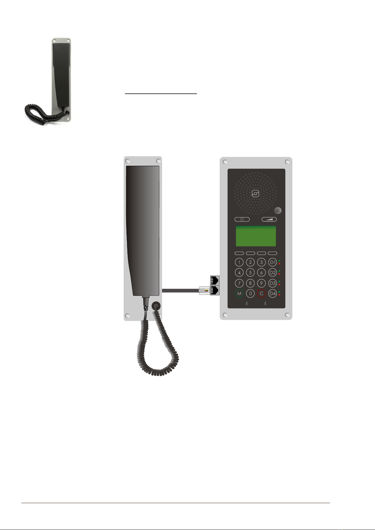
2.4 Handset
● item no. 1008097100
The Handset accessory is available for the IP Flush Master Station.
To connect the handset:
● Insert the RJ11 plug of the handset into the lower port of the dual
RJ11 ports on the lower left of the station.
Figure 8 Installing the Handset
--
++
STENTOFON
RJ11
Plug
Dual
RJ11
Ports
Handset IP Flush Master Station

11
IP Master Station Installation & Conguration
A100K10788
2.5 Headset
The IP Flush Master Station has an RJ11 port for a Headset accessory.
"Zenitel does not supply headsets. Use headsets with an RJ11 plug.
To connect the headset, insert the RJ11 plug of the headset into the
upper port of the dual RJ11 ports on the lower left of the station.
Figure 9 Installing the Headset
Connector pin settings for the headset can be found in Appendix A:
Station Board Connections.
--
++
STENTOFON
RJ11
Plug
Dual
RJ11
Ports
Headset
IP Flush Master Station
12 A100K10788
IP Master Station Installation & Conguration
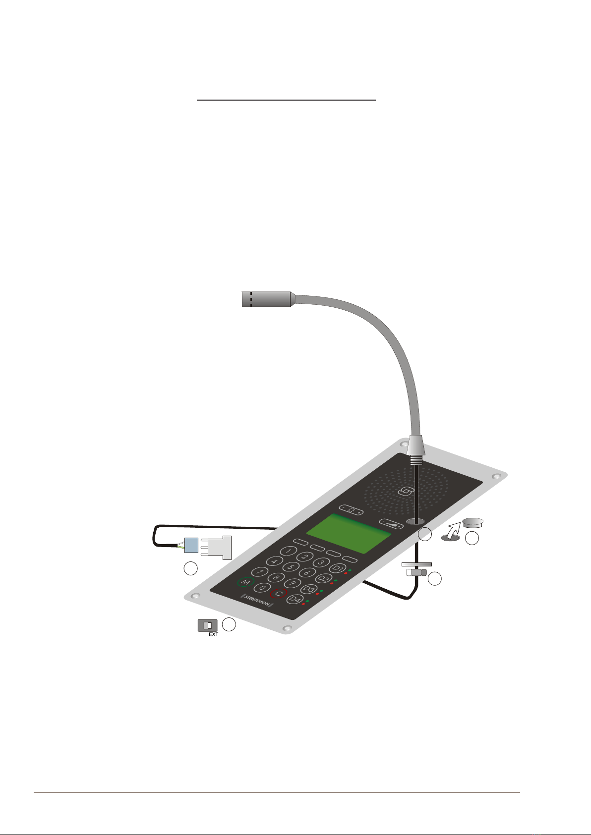
2.6 GooseneckMicrophoneforIPFlushMaster
● item no. 1008097500
ToinstalltheGooseneckMicrophone:
1. Remove the cover plug from the opening for the microphone on the
front panel.
2. Thread the microphone cable through the opening, the lock washer
and nut.
3. Tighten the nut on the microphone’s threaded stud.
4. Insert the microphone’s IDC socket into the upper two pins of the
3-pin header (J7) located at the lower left side of the station. The
signal wire (white) should be on the top pin while the ground wire
(green) should be on the bottom pin.
5. Slide the S1 switch (bottom back of station) to EXT to activate the
external microphone function.
Figure 10 Installing the Gooseneck Microphone for Flush Master
J7
3-pin header
INT
S1
4
3
21
5
Gooseneck Microphone
Cover Plug
Nut
IDC Socket
Slide Switch
IPFlushMasterStation
Microphone Cable

13
IP Master Station Installation & Conguration
A100K10788
2.7 GooseneckMicrophoneforIPDualDisplay
● item no. 1007007010
ToinstalltheGooseneckMicrophone:
1. Flip the station over so that the bottom side is facing up
2. Slide the tab on the microphone foot into the slot on the side of the
station
3. Secure the microphone foot to the station with a screw as shown
4. Plug the microphone jack into the socket just above the RJ45 port
RJ45 Tab
Slot
Figure 11 Installing the Gooseneck Microphone for Dual Display
"The internal microphone is automatically disconnected when the gooseneck mi-
crophone jack is inserted.
2.8 Input/OutputConnections
There are I/O connection options for the IP Flush Master Station, the IP
OR Master Station, and the IP Master Station Kit.
These connections are used for as relay contacts for door lock control
and external I/O devices.
For pin settings on the P3 and P4 connectors on the station board, see
Appendix A Station Board Connections.
14 A100K10788
IP Master Station Installation & Conguration
2.9 IP DAK-48 Unit
The IP DAK-48 unit expands the IP Flush Master station with an
additional 48 Direct Access Keys.
"Before installation, disconnect power from the IP Flush Master station
The accompanying RJ45-RJ45 cable is used to install the DAK unit on an
IP Flush Master station. This cable has an RJ45 plug at both ends. The
two ends are interchangeable. Up to two DAK units can be installed per
station. Each DAK unit has two RJ45 ports, one located on the left side
and one on the right side.
To install the IP DAK-48 Unit:
1. Plug one end of the RJ45-RJ45 cable into the RJ45 port on the right
of the station (when the station is viewed from the front).
2. Plug the other end of the RJ45-RJ45 cable into the left (when the unit
is viewed from the front) RJ45 port on the DAK unit.
Figure 12 Installing the IP DAK-48 Unit
To add another DAK unit, plug one end of an RJ45-RJ45 cable into the
RJ45 port of the installed unit and plug the other end into the RJ45 port of
the new unit.
--
++
STENTOFON STENTOFON
IP DAK-48 Unit IP DAK-48 Unit
IP Flush Master Station
STENTOFON
RJ45 - RJ45 Cable RJ45 - RJ45 Cable

15
IP Master Station Installation & Conguration
A100K10788
3 Conguration
There are two ways of conguring the IP Master Station:
● Using the station keypad
● Using a web browser
For station conguration, there are essentially three parameters to set:
● AlphaCom IP address
● Station directory number
● Station IP address
"Advanced conguration settings as described in section 3.3 are not mandatory for
the station to function properly.
3.1 CongurationViaStationKeypad
When the IP Master Station is not connected to the AlphaCom exchange,
an ofine menu is displayed. The ofine menu can be used to congure
the station and is navigated with the 4 buttons below the display. The
button on the left is used as a Select or Ok button as shown in the
display, while the button on the right is used as a Back button. The two
buttons in the middle are used to navigate up or down according to the
arrows. When conguring IP settings, the M key is used to insert a “.”
(dot) and the right-middlebutton is used to delete a character.
Main menu
To enter the setup menu:
1. Press the Setup button on the left
2. Enter the password 1851
3. Press the Ok button
A menu with ve options will be displayed. Use the two arrow buttons
in the middle to navigate through the menu options. Press the Sel
button on the left to select the menu option and the Ok button to conrm
data entered. When entering data, the left-arrow is used for deleting
characters.
Station info
This shows the station MAC and IP addresses, the congured AlphaCom
IP address and software version.
IPsettings
Choose between DHCP and STATIC IP address. If STATIC is chosen, it
is possible to congure the IP address, mask and gateway.
AlphaComSettings
Set the IP address of AlphaCom that the station shall connect to, and the
directory number of the station. If a directory number is not entered, the
station will register with its MAC address.
No AlphaCom conn.
Setup
State:
- Enter password
1851
Ok Esc
- Main menu -
Station info -->
IP settings -->
AlphaCom Settings -->
Load defaults -->
Restart -->
Sel Back
Back
Back
Sel
Back
Sel

16 A100K10788
IP Master Station Installation & Conguration
Load defaults
This will load the factory default settings.
● Press the Sel button to load the default settings.
Restart
This will restart the station.
● Press the Sel button to restart the station.
Restart the station to apply new settings.
3.2 CongurationViaWebBrowser
3.2.1 IPMasterStationWebInterface
The IP Master Station features an embedded web server, which allows
users to log in via a standard web browser.
At commissioning, the IP station needs to be congured to enable it to
subscribe to an AlphaCom server/exchange. To do this, your PC and the
IP station have to be connected together via a PoE switch using network
cables:
● Connect the PC to the PoE switch
● Connect the LAN port on the IP station to the PoE switch
Figure 13 LAN Port on IP Flush/OR Master Stations
The factory default IP address of the station is 169.254.1.100. In order
for your PC to communicate with the station it is necessary to change
its Internet Protocol Properties to use an IP address that is in the
same range as 169.254.1.100, e.g. 169.254.1.1 with subnet mask
255.255.255.0.
Figure 14 LAN Port on IP Desktop Master Station
After the IP properties have been changed, access the station by logging
into the web interface using a standard web browser:
1. Open a web browser
2. In the browser’s address bar, type the default IP address
169.254.1.100 and press the ENTER key
- The station login page will be displayed.
To log into the station:
1. Click Login
2. Enter the default User name: admin
3. Enter the default password: alphaadmin
The Station Information page will now be displayed, showing the IP
station conguration including the MAC address which needs to be
entered into the AlphaPro programming tool.
Back
Sel
Press to set.
Back
Sel
Press to restart
LAN AUX
LAN
AUX

17
IP Master Station Installation & Conguration
A100K10788
Use the menu bar at the top of each page to browse through the different
pages.
3.2.2 StationMainSettings
● Click Station Main > MainSettings to access the page for
conguring station mode and IP parameters.
Station Mode
● Select the Use Alphacom radio-button
RegistrationSettings
● Enter the IP address of the AlphaCom server/exchange in which the
IP station is to be a subscriber in the AlphaCom IP-address eld.
● Enter the directory number of the station in the Directory Number
eld.
- If a directory number is not entered, the station will register with its
MAC address. The MAC address is found on the Station Info page
and needs to be entered into the AlphaPro programming tool.
CCoIPStation–IPSettings
●DHCP – Select this option if the IP station shall receive IP Settings
from a DHCP server.
●Static IP – Select this option if the IP station shall use a static IP
address. Enter values for:
-IP-address
-Subnet-mask
-Gateway
● Click Save followed by Apply to apply the new conguration
settings.

18 A100K10788
IP Master Station Installation & Conguration
3.3 AdvancedCongurationOptions
"The conguration settings described in this section are not mandatory.
3.3.1 Noise Reduction
Active noise reduction uses advanced signal processing algorithms
in the IP stations. These algorithms will try to identify the noise signal
(background repetitive audio). When noise is identied, the algorithm
lters out the noise while retaining the voice signal. If you set noise
reduction at a high level, more of the voice signal will also be ltered out.
The range of ltering levels are from 0 to 7 for the station characteristics
to be tuned optimally to the environment. The settings will take effect
immediately after being saved, making it easy to test various parameters
while the conversation is active.
Noise Reduction Level is congured in the web server of the IP station.
● Select AdvancedConguration > Audio from the menu
Noise Reduction Levels
● Level 0 means that noise reduction is disabled
● Level 1 gives a maximum noise reduction of 0.2 dB
● Level 2 gives a maximum noise reduction of 6.2 dB
● Level 3 gives a maximum noise reduction of 12.2 dB
● Level 4 gives a maximum noise reduction of 18.3 dB
● Level 5 gives a maximum noise reduction of 24.3 dB
● Level 6 gives a maximum noise reduction of 30.3 dB
● Level 7 gives a maximum noise reduction of 36.3 dB
By default, the noise reduction level is disabled, i.e. set to 0. In very noisy
environments, we recommend setting the noise reduction level to 4. At
this level, the audio quality is good when quiet, and when noisy, most of
the noise is ltered out.
● Set the level required in the Noise Reduction Level scrolldown box
and click Save.
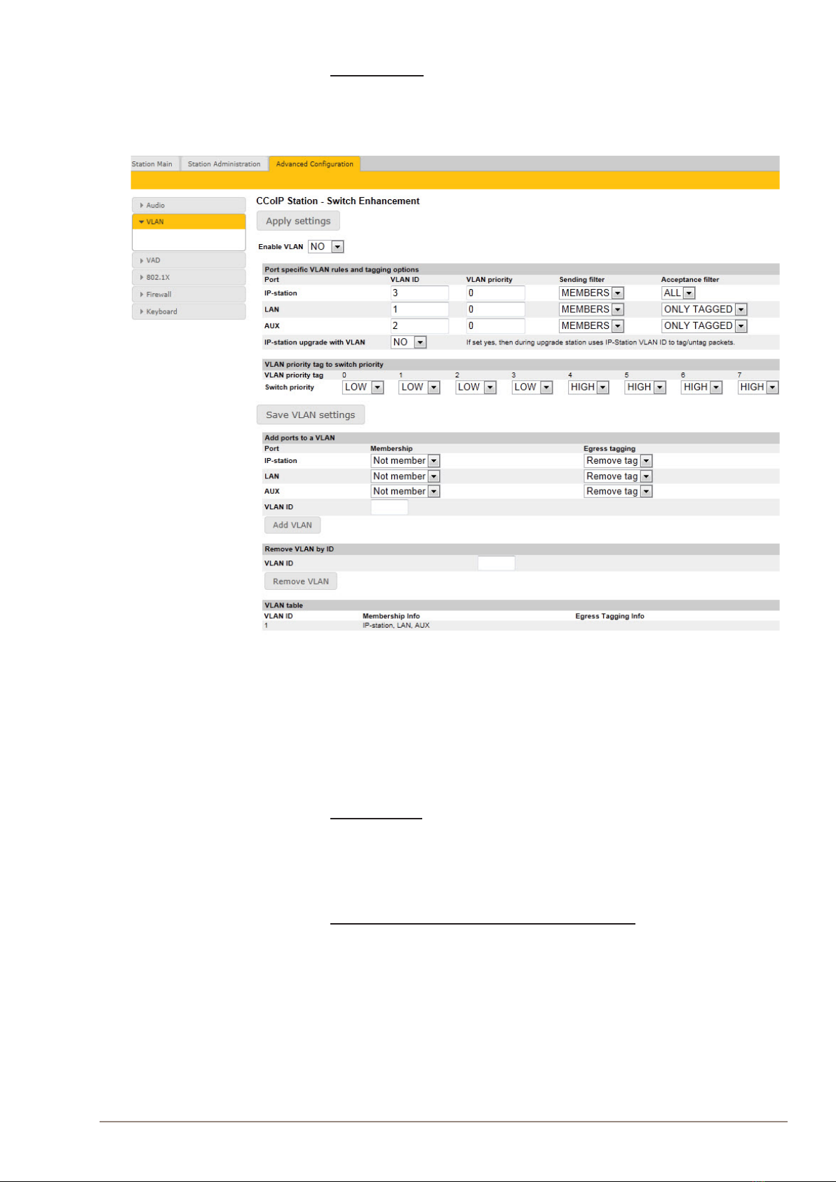
3.3.2 VLAN
VLAN Tagging or IEEE 802.1Q is a networking standard allowing multiple
bridged networks to transparently share the same physical network
link without leakage of information between networks. IEEE 802.1Q —
along with its shortened form dot1q — is commonly used to refer to the
encapsulation protocol used to implement this mechanism over Ethernet
networks.
"STENTOFON IP Stations support 802.1Q as from rmware version 01.09.3.0.
19
IP Master Station Installation & Conguration
A100K10788
User interface
VLAN is congured in the IP station web interface.
● Select AdvancedConguration > VLAN from the menu
Clicking the Applysettings button will apply the chosen settings. With
the exception of a restart, the saved settings will not come into effect until
Applysettings is clicked.
EnableVLAN
This option determines whether the switch uses 802.1Q or not. If this is
enabled, the switch is VLAN aware. Select YES or NO from the dropdown
menu.
PortspecicVLANrulesandtaggingoptions
Here, it is possible to specify which VLAN ID and priority the ports should
assign untagged packets to. Tagged packets are not changed.
●VLANID has a value range from 0 to 4094. It species which VLAN
ID tag to add to a packet.
●VLANpriority has a value range from 0 to 7. It species which
VLAN priority tag to add to a packet.
●Sendinglter species whether a given port will only send to VLANs
which it is a member of or all VLANs. For example, if the chosen
option is MEMBERS then a packet with VLAN ID 1 at the LAN port
will only reach another port which is a member of VLAN ID 1. Select

20 A100K10788
IP Master Station Installation & Conguration
MEMBERS or ALL from the dropdown menu.
●Acceptancelter species whether a port will accept only tagged
packets or all packets. The option ONLYTAGGED should only be
used against VLAN aware devices which tag packets. Select ONLY
TAGGED or ALL from the dropdown menu.
● If the IP-stationupgradewithVLAN scrolldown box is set to YES
the IP station will send tagged packets during the upgrade.
VLANprioritytagtoswitchpriority
Here, it is possible to specify how the switch should queue the packets
with VLANprioritytag.
●Switch priority: Select HIGH or LOW from the dropdown menu. By
default, packets with VLAN priority tags from 4 to 7 are set to the
HIGH priority queue.
AddportstoaVLAN
Here, it is possible to determine whether the ports should be members
of the specied VLAN. There is also a setting for specifying whether the
ports should strip or keep the VLAN tag when sending egress packets.
●Membership determines whether the port is a member of the
specied VLAN or not. Select Not member or Member from the
dropdown menu.
●Egresstagging determines whether the port should remove VLAN
tags or keep them for the specied VLAN. Select Removetag or
Keeptag from the dropdown menu.
Clicking the AddVLAN button will add the current chosen settings to the
VLANtable below. If a VLAN in the VLANtable already exists with the
chosen VLANID, then the settings will be updated.
RemoveVLANbyID
Here, it is possible to determine which VLAN is to be removed from the
VLANtable by specifying the VLANID, then clicking the RemoveVLAN
button.
VLANtable
The VLANs that the ports are members of are listed under the
Membership Info column. The table also lists the ports that keep the
VLAN tag when sending egress packets; this is shown under the Egress
TaggingInfo column. The VLANtable can accomodate a maximum of
63 VLANs.
"The DHCP address is received before the switch is VLAN aware (during startup).
Either trunk all VLANs or set the DHCP server which should reach the IP station
on a native VLAN.
3.3.3 NetworkAccessControl
IEEE 802.1X is an IEEE Standard for Port-based Network Access
Control (PNAC) By “port” we mean a single point of attachment to the
LAN infrastructure. It provides an authentication mechanism to devices
wishing to attach to a LAN, either establishing a point-to-point connection
or preventing it if authentication fails.
"STENTOFON IP Stations support 802.1X as from rmware version 01.09.3.0.
User interface
802.1X Network Access Control is congured from the IP station web
interface.
Table of contents


