Amit RRAS-GNM/x User manual

rras-gnmx_g_en_100
RRAS-GNM/x
Microphone unit
Operation guide
Version 1.00

RRAS-GNM/X
rras-gnmx_g_en_100 2/22
AMiT, spol. s r.o. does not provide any warranty concerning the contents of this
publication and reserves the right to change the documentation without
obligation to inform anyone or any authority about it.
This document can be copied and redistributed under following conditions:
1. The whole text (all pages) must be copied without any changes.
2. All redistributed copies must retain the AMiT, spol. s r.o. copyright notice
and any other notices contained in the documentation.
3. This document must not be distributed for purpose of making profit.
The names of products and companies used herein can be trademarks or
registered trademarks of their respective owners.
AMiT is a registered trademark.
Copyright (c) 2013, AMiT, spol. s r. o.
Producer: AMiT, spol. s r. o.
Naskové 3/1100, 150 00 Praha
www.amit-transportation.com

RRAS-GNM/X
3/22 rras-gnmx_g_en_100
Contents History of revisions.........................................................................................4
Related documentation...................................................................................4
1. Introduction..........................................................................................5
2. Technical parameters..........................................................................6
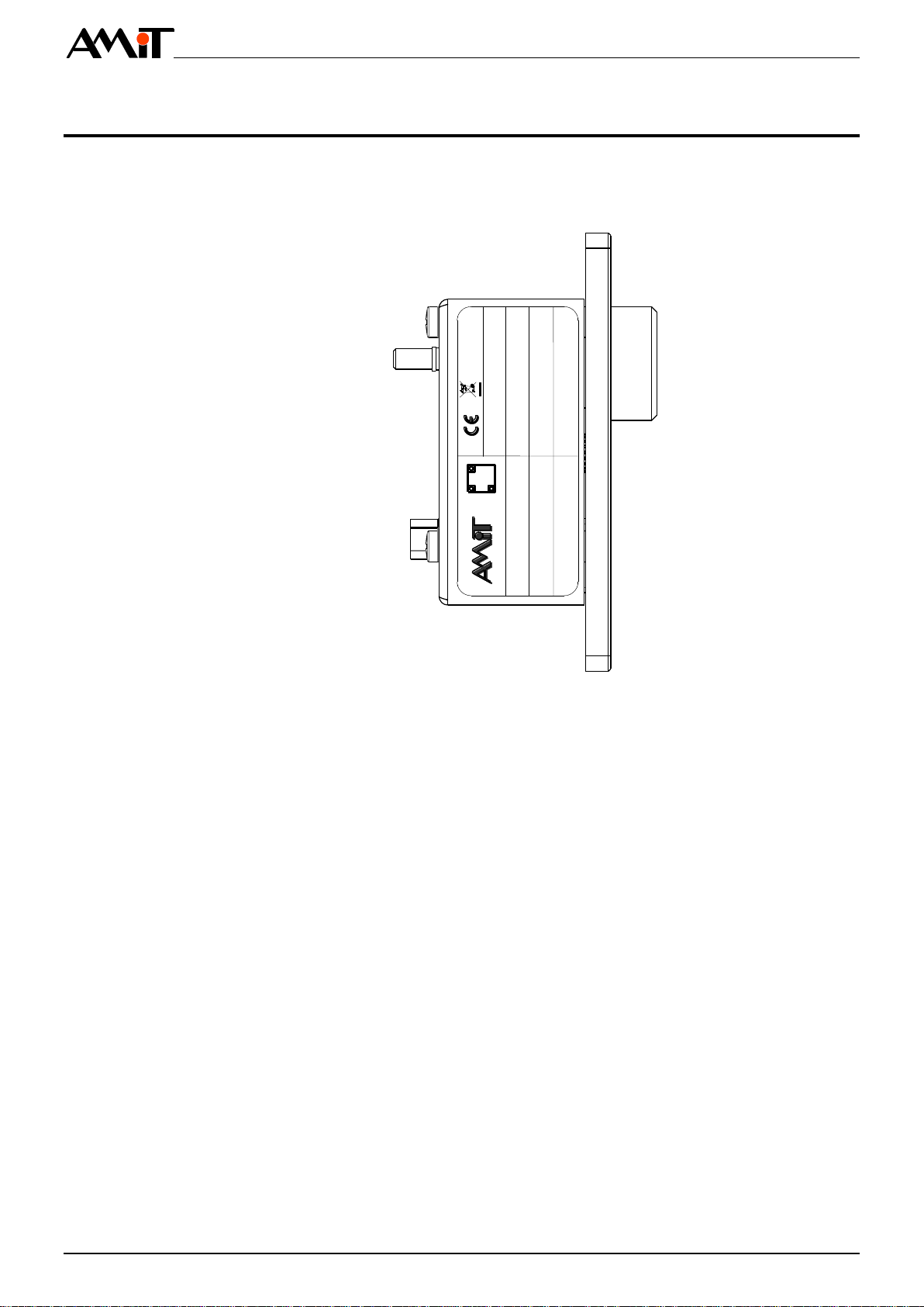
2.1. Dimensions.....................................................................................................7
2.2. Recommended drawing symbol .....................................................................8
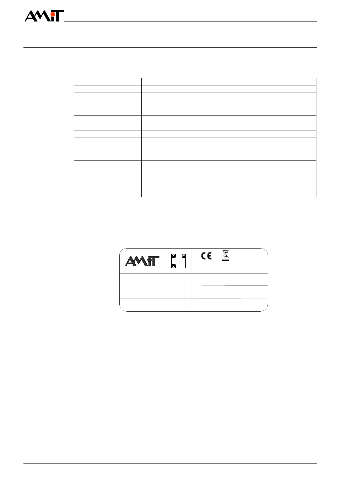
3. Product marking ..................................................................................9
3.1. Producer type label.......................................................................................10
4. Conformity assessment ....................................................................11
4.1. Other tests....................................................................................................12
5. Power supply......................................................................................13
6. User interface / controls....................................................................14
6.1. Microphone...................................................................................................14
6.2. Buttons.........................................................................................................14
6.3. Corner indicators..........................................................................................14
6.4. Contour backlight..........................................................................................15
6.5. Design of front panel ....................................................................................15
7. Microphone unit interface.................................................................16
7.1. Wiring of interconnection cable.....................................................................16
8. Mounting.............................................................................................17
8.1. Mounting apertures.......................................................................................17
8.2. Installation rules............................................................................................17
9. Ordering Information and package contents ..................................18
9.1. Package contents.........................................................................................18
10. Packing ...............................................................................................19
11. Storing.................................................................................................20
12. Maintenance .......................................................................................21
13. Disposal..............................................................................................22

RRAS-GNM/X
rras-gnmx_g_en_100 4/22
History of revisions
Document name: rras-gnmx_g_en_100.pdf
Author: Jaroslav Šach
Revision
Date
Changes
100
18. 10. 2017
New document
Related documentation
1. Operation guide for RRAS-MCT/D20
file: rras-mctd20_g_en_xxx.pdf
2. Operation guide for RRAM-MCT/D20
file: rram-mctd20_g_en_xxx.pdf

RRAS-GNM/X
5/22 rras-gnmx_g_en_100
1. Introduction
RRAS-GNM/x is a microphone unit for rolling stock, designed for usage with
unit RRAM-MCT/D20 (RRAS-MCT/D20). Unit is intended for use in driver’s
cabin.
▪Microphone with metal flexible pipe
▪2 illuminated control buttons
▪2 LED indicators
▪Interface for direct connection with unit RRAS-MCT/D20
▪Mounting into panel
Proper function of RRAS-GNM/x is guaranteed only when connecting
microphone with unit RRAM-MCT/D20 (RRAS-MCT/D20).
Basic features
Note

RRAS-GNM/X
rras-gnmx_g_en_100 6/22
2. Technical parameters
Frequency range
150 Hz to 8 kHz (±5 dB)
Sensitivity
-72 dB ±3 dB (0 dB = 1 µbar @ 1 kHz)
Mic type
Directional
Flexible pipe length
440 mm
Buttons
2 ×
Control buttons backlight
Yes, adjustable intensity
Lifetime
1 000 000 strokes
Grip strength
5.5 N
LED
2 × corner indicator
LED colour
Red
Voltage
Max. 2.7 V DC
LED current
Max. 50 mA
Connection point
Connector D-sub DE-9, socket
(connector fixing by UNC4-40 thread screw)
Amplifier powering
Phantom 3.3 V DC
Amplifier power consumption
Max. 50 mA
Galvanic isolation
No
Connection point
Connector D-sub DE-9, socket
(connector fixing by UNC4-40 thread screw)
Mechanical design
Panel to be built into wall
Colour front panel
rear cover
foil
text
RAL 9005
RAL 9005
RAL 9005 RAL 7016
RAL 9010
Mounting
4 × M4 bolt with flat head
Ingress protection rate
IP30
Weight –netto
–brutto
0.4 kg ±5 % , 0.5 kg ±5 %
0.6 kg ±5 % , 0.9 kg ±5 %
Dimensions (w × h × d)
(86 × 65 × 42 ) mm
Operating temperature range
-40 °C to + 70 °C
Storage temperature range
-40 °C to + 70 °C
Maximum ambient humidity
< 95 % non-condensing
Expected MTBF
> 300 000 h
Expected lifetime
15 years *)
Buttons
1 000 000 strokes
*) Full range warranty is not provided to the listed components, but only for
time of expected component lifetime or presumptive life expectancy.
Microphone
input
Controls
Indication
elements
Power supply
Mechanics
Temperatures
Others
Components
with reduced
lifetime
Note

RRAS-GNM/X
7/22 rras-gnmx_g_en_100
Equipment is intended to operate up to 1 400 m above the sea level.
Equipment is designed to meet the Temperature Class TX.
According to EN 61373:2010 standard, the equipment is classified in terms of
vibrations into Category 1, Class A (mounting to vehicle body).
The device is not classified according to EN 50128:2011 Railway applications –
Communications, signalling and processing systems –Software for railway control
and protection systems.
The device is not classified according to EN 50129:2003 Railway applications –
Communication, signalling and processing systems –Safety related electronic sys-
tems for signalling.
2.1. Dimensions
440 mm / 800 mm
Fig. 1 - RRAS-GNM/x dimensions
Claims of EN
50155:2007
Safety
classification
60
50
65
54
75
5
o 5
42
28
86

RRAS-GNM/X
rras-gnmx_g_en_100 8/22
2.2. Recommended drawing symbol
Following drawing symbol is recommended for the RRAS-GNM/x Microphone
unit.
RRAS-GNM/x
X1
D-sub DE-9
Fig. 2 - Recommended drawing symbol for RRAS-GNM/x

RRAS-GNM/X
9/22 rras-gnmx_g_en_100
3. Product marking
RRAS-GNM/x computer has producer's type label on its rear side.
For location of specific marking, see Fig. 3 - Location of label on unit’s cover.
TYPE RRAS-GNM/x
S/N AAxxxxx
POWER FANT.
WEIGHT 0.4 kg
TEST OK-OP
HiPot HiPot - OK
DATE 11.05.2017
Fig. 3 - Location of label on unit’s cover

RRAS-GNM/X
rras-gnmx_g_en_100 10/22
3.1. Producer type label
Unit has a producer type label attached to its side. Included data are summa-
rized in the table, for example of label design, see Fig. 4 - Example of type la-
bel.
Description
Data
Note
–
Logo AMiT
Producer logo
–
QR code
Producer QR code
TYPE
RRAS-GNM/x
Product type designation
S/N
AAxxxxx
Serial number
POWER
24 V DC / PHANTOM
Power supply voltage / Con-
sumption
WEIGHT
0.40 kg *)
Weight
TEST
OK-xx
Routine testing result
HiPot
HiPot-OK
HiPot test result
DATE:
dd.mm.yyyy
Production date
–
Logo CE
The Device is compliant with EU
legislation and directives
–
Crossed out dustbin logo
Disposal of the Device is a sub-
ject to regulations on the dispos-
al of electronic waste
*) Stated weight depends on specific unit type. See chapter Ordering Infor-
mation
TYPE RRAS-GNM/x
S/N AAxxxxx
POWER FANT.
WEIGHT 0.4 kg
TEST OK-OP
HiPot HiPot - OK
DATE 11.05.2017
Fig. 4 - Example of type label
Note

RRAS-GNM/X
11/22 rras-gnmx_g_en_100
4. Conformity assessment
The equipment meets the claims of Czech government decree NV616/2006; the
conformity assessment has been performed in accordance with harmonized
standard EN 50121-3-2:2006.
Tested in accordance
with standard
Type of test
Class
EN 55011:2009
Industrial, scientific and medical equipment
–Radio-frequency disturbance characteris-
tics –Limits and methods of measurement
complies
EN 61000-4-2:2009
Electromagnetic compatibility (EMC) –Part
4-2: Testing and measurement techniques -
Electrostatic discharge immunity test
complies
EN 61000-4-3:2006
Electromagnetic compatibility (EMC) –Part
4-3: Testing and measurement techniques –
Radiated, radio-frequency, electromagnetic
field immunity test 800 MHz to 1000 MHz
20 V/m *)
EN 61000-4-3:2006
Electromagnetic compatibility (EMC) –Part
4-3: Testing and measurement techniques –
Radiated, radio-frequency, electromagnetic
field immunity test, 1000 MHz to 2100 MHz
10 V/m *)
EN 61000-4-3:2006
Electromagnetic compatibility (EMC) –Part
4-3: Testing and measurement techniques –
Radiated, radio-frequency, electromagnetic
field immunity test, 2100 MHz to 2500 MHz
5 V/m *)
EN 61000-4-4:2012
Electromagnetic compatibility (EMC) –Part
4-4: Testing and measurement techniques –
Electrical fast transient/burst immunity test,
power supply
4 kV
EN 61000-4-4:2012
Electromagnetic compatibility (EMC) –Part
4-4: Testing and measurement techniques -
Electrical fast transient/burst immunity test,
input
2 kV
EN 61000-4-5:2007
Electromagnetic compatibility (EMC) –Part
4-5: Testing and measurement techniques –
Surge immunity test, power supply
4 kV
EN 61000-4-6:2009
Electromagnetic compatibility (EMC) –Part
4-6: Testing and measurement techniques –
Immunity to conducted disturbances, in-
duced by radio-frequency fields
10 V *)
EN 45545-2
Railway applications –Fire protection on
railway vehicles –
Part 2: Requirements for fire behaviour of
materials and components
HL3

RRAS-GNM/X
rras-gnmx_g_en_100 12/22
4.1. Other tests
This product was assessed and approved for use in railway applications
according to standards:
Tested in accordance
with standard
Type of test
Classification
EN 50155:2009
Electronic equipment used on rolling
stock
Complies
EN 50121-3-2:2006
Railway applications –Electromagnetic
compatibility
Complies
EN 61373:2010
Railway applications –Rolling stock
equipment –Shock and vibration tests
Complies
EN 60068-2-1:2007
Environmental testing –Part 2-1: Tests
–Test A: Cold
Complies
EN 60068-2-2:2007
Environmental testing –Part 2-2: Tests
–Test B: Dry heat
Complies

RRAS-GNM/X
rras-gnmx_g_en_100 14/22
6. User interface / controls
2
3
4
6
5
1
Fig. 5 - RRAS-GNM/x user elements
Position
User element title
1
Microphone
2
Corner indicator INT
3
INT button
4
Buttons contour backlight
5
EXT button
6
Corner indicator EXT
6.1. Microphone
Microphone is mounted on flexible pipe.
6.2. Buttons
RRAS-GNM/x unit provides the user two control buttons. Their particular
function is given by superior system software.
6.3. Corner indicators
Corner indicators serves for indication of selected function. Particular meaning
of indication LEDs is given by RRAS-MCT/D20 unit software.
The light intensity of indicators can be adjusted independently on intensity of
contour backlight.
User elements

RRAS-GNM/X
15/22 rras-gnmx_g_en_100
6.4. Contour backlight
The contour backlight of buttons highlights the location of controls on the panel,
thereby allows an easier orientation upon decreased visibility.
Intensity of contour backlight can be adjusted independently on intensity of
corner indicators.
6.5. Design of front panel
Text version Pictogramversion
Colour:
Foil - RAL 9005
Text - RAL 9010
Colour:
Foil - RAL 7016
Text - RAL 9010
Fig. 6 - Panel colour and design

RRAS-GNM/X
rras-gnmx_g_en_100 16/22
7. Microphone unit interface
Standard shielded RS232 cable with connectors D-sub DE-9 is used for
connecting microphone to the RRAS-MCTD/20 (RRAS-MCTD/20) unit.
Connector is located on rear cover of RRAS-GNM/x unit. Use shielded RS232
cable for connection.
7.1. Wiring of interconnection cable
D-sub DE-9
plug
D-sub DE-9
socket
1
2
3
4
5
6
7
8
9
1
2
3
4
5
6
7
8
9
Fig. 7 - Wiring of connection cable
D-sub DE-9 plug
D-sub DE-9 socket
1
1
2
2
3
3
4
4
5
5
6
6
7
7
8
8
9
9
Wiring of
cable pins

RRAS-GNM/X
17/22 rras-gnmx_g_en_100
8. Mounting
The RRAS-GNM/x unit is designed to mount onto operation panel in vehicle
driver’s cabin. Use M4 bolts with flat cylindrical head for fastening! Microphone
can be mounted in any position.
8.1. Mounting apertures
o 5,0
52,0
54,0
62,0
75,0
Fig. 8 - RRAS-GNM/x mounting holes
8.2. Installation rules
Standard RS232 interface connection cable can be used for connecting the
RRAS-GNM/x unit to superior system. Maximum cable length is ca. 2 m.
Connect the PE terminal on rear cover with vehicle frame. Connection must be
realized by conductor with as low as possible impedance. Technical parameters
of unit are guaranteed only when these wiring principles are applied.
Connection
with superior
system
Note

RRAS-GNM/X
rras-gnmx_g_en_100 18/22
9. Ordering Information and package contents
RRAS-GNM/A
Microphone unit - 440 mm, 0.4 kg ±5 %, Text version
RRAS-GNM/A11
Microphone unit - 440 mm, 0.4 kg ±5 %, Pictogram version
RRAS-GNM/B
Microphone unit - 800 mm, 0.5 kg ±5 %, Text version
RRAS-GNM/B11
Microphone unit - 800 mm, 0.5 kg ±5 %, Pictogram version
*) Differences also shown on Fig. 6 - Panel colour and design
9.1. Package contents
Part
Quantity
RRAS-GNM/x unit
1
Routine testing protocol
1
Insulation testing protocol
1
Certificate of product quality and completeness
1
Microphone
unit *)
RRAS-GNM/x

RRAS-GNM/X
19/22 rras-gnmx_g_en_100
10. Packing
The Unit is stored in a paper box and is protected against impacts with special
pads. Package dimensions are listed in chapter Technical parameters.
Sticker on the box contains following information:
Item
Description
TYPE
RRAS-GNM/x
NETTO
0.4 kg *)
BRUTTO
0.6 kg *)
QTY
1 pc
S/N
Serial number
AMiT logo
–
QR code
–
CE sign
–
*) Stated weight depends on specific unit type. See chapter Ordering In-
formation
TYPE
NETTO
BRUTTO
QTY
S/N ABCD
1 PC
0.6 kg
0.4 kg
RRAS-GNM/x
WH
D
Fig. 9 - Box dimensions and label design
Box
Label
Note

RRAS-GNM/X
rras-gnmx_g_en_100 20/22
11. Storing
To prevent damage of the device, follow these rules.
Product in original packaging must be stored under the conditions specified in
chapter Technical parameters. Product must not come into contact with water,
oil or any other liquids, that can damage the packaging.
Box with the device can be stored in any position. If boxes are stockpiled,
weight acting on the top side of the box must not exceed 10 kg. All load must
be evenly spread over the entire upper side of the box.
Unpacked product must be stored only under the conditions specified in chapter
Technical parameters. Product may not come into contact with water or any
other liquids, and must be placed in a clean environment without excessive
dust, sawdust, etc.
The product can be placed only on surface that will not cause damage to its
electronics or surface (for example soft fabrics, bubble wrap, soft protective
rubber pad, etc.).
Product connectors or its display area must not rely on anything.
If storing rules are not respected, the warranty might be lost.
Product in a
package
Product
without
package
Table of contents
Other Amit Microphone manuals