Display Screen
① Transmitter A
② Transmitter B
③ Transmitter Signal
④ Transmitter Power
⑤ Transmitter Power Level
⑥ Sound Eect Of Left Channel
⑦ Gain Value Of Left Channel
⑧ Sound Eect Of Right
Channel
⑨ Gain Value Of Right Channel
⑩ Receiver
⑪ Receiver Power
⑫ Power Level Of Receiver
Microphone Power Level
⑬ Gain Value Of Receiver
⑭ Frequency Setting/Version
Information
⑮ Output Channel Option
⑯ USB Port Output Gain
⑰ 3.5Mm Port Output Mode
⑱ 3.5Mm Port Output Gain
⑲ Monitoring Port Output Mode
⑳ Output Channel Option
㉑ Monitoring Port Volume
Interface Selection and Button Operation
Setting Content Description
1. Press the Setting button or the Up and Down Option button. The
screen highlights shows the selected panel.
2. Press the Up and Down option buttons to switch the panel, and then
press the Settings button to select the operation page of the settings
panel .
3. On the operation page, press the Up and Down button to switch
between dierent parameter categories. Press the operation button again
as the screen ashes as a prompt. Press the Up and down option key to
switch between dierent options of this parameter.
4. Press the Power/Return button to return to the previous stage.
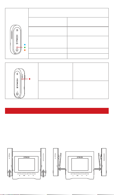
1. When the TX A/B memory card is full, the icon will blink
red. After selecting the panel of TX A/B, press the setting
button to enter the operation page to mute the microphone
and view the recording duration.
2. On the operation page of the RX panel, you can mute the receiver
microphone and modify the gain.
3. Enter The Operation Page Of The Channel Panel:
(1) The noise reduction gear of the channel can be changed. There are
three level noise reduction: 75/150/300.
(2) The high frequency lifting of the channel can be set on/o.
(3) 5 EQ sound eects can be selected for the channel.
(4) The gain adjustment of the sound channel can be set.
4. Enter the frequency setting operation panel to open the frequency
and view the version. When the frequency matching function is enabled,
a status pop-up will be displayed, indicating the frequency matching
succeeds or fails.
5. The output panel operation page is displayed. The output of the 3.5mm
port is (TRRS/TRS), and dierent microphones are selected for dierent
channels.
The function of type -C port is as follows: charging only/ data reading
+ charging/ reading L transmitter memory le/ reading R transmitter
memory le/ mobile phone mode.
6. Enter the operation page of the monitoring panel, you can adjust the
monitoring volume of the receiver and switch the monitoring port mode.
After the 3.5mm monitoring port is set from monitoring to output, the
output mode and volume are associated with the setting of the out port.
NOTE:
1. Select Phone mode in the Setting if heat occurs when using the Apple
adapter or Type-C connection to the phone. In this case, the phone will
not supply power to the receiver in reverse, reducing the heat generated
by the interface, and the phone will powered up longer.
2. Please check whether the receiver is set to TRRS, when using 3.5
TRRS audio cable to connect mobile phone. (TRRS is for mobile phone,
TRS is for camera).
Specications
Wireless Transmission
RF Frequency Band
Working Distance
Sampling Rate
Bit Depth
RF Output Power
Battery Capacity
Monitor
Monitor Volume
Built-in Memory
Battery Charging Time
Battery Life
Dimensions
Material
Weight
Digital 2.4GHz
2.4G
820ft/250m(LOS area)
48KHz
16Bit
20dB
260mAh, Lithium Battery,
3.5mm In-Ear monitoring
1-5 level
8G
2H
5H
62*22*20mm
ABS
15g
TX Transmitter
Form Factor
SNR
Polar Pattern
Frequency Range
Sensitivity
Maximum SPL
MEMS Silico Mic
﹥ 75dB
Omnidirectional
50-20KHz
-28dB (±3dB, re 1V/Pa at 1KHz)
110dB SPL (at 1KHz)
Microphone
Wireless Transmission
RF Frequency Band
Working Distance
Sampling Rate
Bit Depth
Display Screen
Number of Input Channels
Number of Output Channels
Monitoring
Monitoring Volum
Audio Output
Audio Output Volum
ANC
High Frequency Boost
Environment Scene Sound
Power Requirements
Battery Type
Battery Charging Time
Battery Life
Dimensions
Material
Weight
Form Factor
SNR
Polar Pattern
Frequency Range
Sensitivity
Maximum SPL
Digital 2.4GHz
2.4G
820ft/250m(LOS area)
48KHz
16Bit
1.8"(240*160)
3
3
3.5mm In-Ear Monitoring
0-15 level
TXA+TXB/RX
-40dB-0dB
75/150/300
4K
Popular、Blues、Scene、Rap、Country
5V 1A
Built-in Lithium Battery, 1800mAh
2.5H
13H
64*62*28mm
ABS
74g
Electret Condenser Mic
﹥ 75dB
Omnidirectional
50-20KHz
-42dB (±3dB, re 1V/Pa at 1KHz)
110dB SPL (at 1KHz)
RX Receiver
Microphone
Thank you for purchasing SYNCO products.
1. Customers are entitled to free replacement or repair service in case
of quality defect(s) found in the product under normal use within 30 days
upon receipt of the product.
2. Original SYNCO products are entitled to 12-month limited warranty
service. The warranty period begins on the date of purchase of brand
new, unused products by the rst end-user.
Within the warranty period, if product defect or failure is attributable to
material defection or technological problem, the defective product or
defective part will be repaired or replaced without charge (service and
materials fee).
1. Faults resulted from inappropriate use of a product without following
its operation specication
2. Articial damage, e.g. crash, squeeze, scratch, or soaking
3. Modications to a product by its user or a third party without prior
written consent of SYNCO, e.g. replacement of element or circuit, label
alteration
4. The code on product is inconsistent with that of warranty certicate,
or the code on the product or warranty certicate is altered or torn o
5. All consumable accessory attached to a product, like cable, wind mu,
battery
6. Faults as a result of force majeure, such as re, ood, lightning, etc.
1. If failure or any problem occurs to your product after purchase, please
contact a local agent for assistance, or you can always contact SYNCO’s
2. Please retain your sales receipt and warranty certicate as proof
of purchase. If any of these documents is missing, only sales return or
chargeable service will be provided.
3. If the SYNCO product is out of the warranty coverage, the service and
the parts cost will be charged.
WARRANTY
Warranty Period
Warranty Exclusions and Limitations
Warranty Claim Procedure


 User manual")


 User manual")