iEP1200 | ETHERNET EMERGENCY PAGING MICROPHONE PANEL PAGE 3
Parts Identification
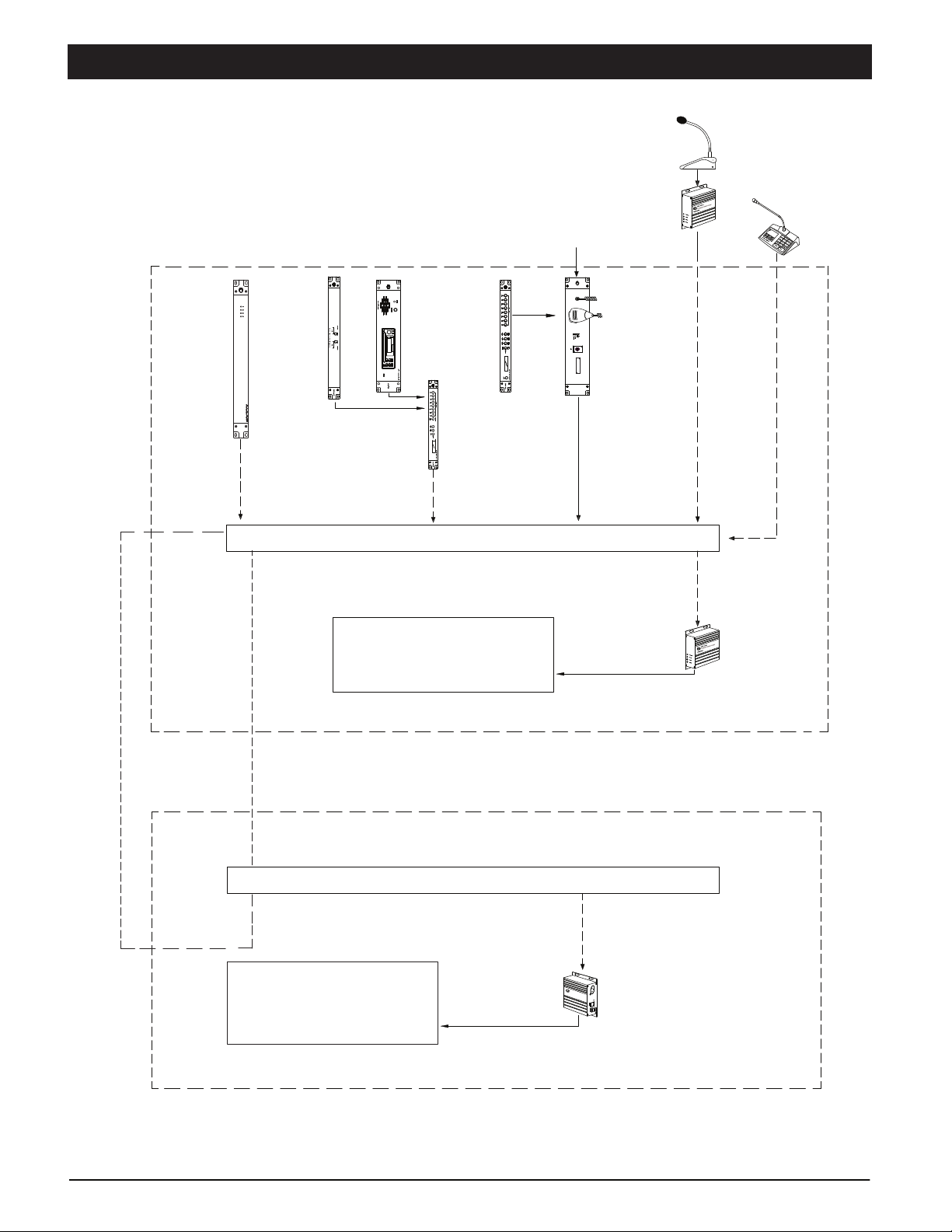
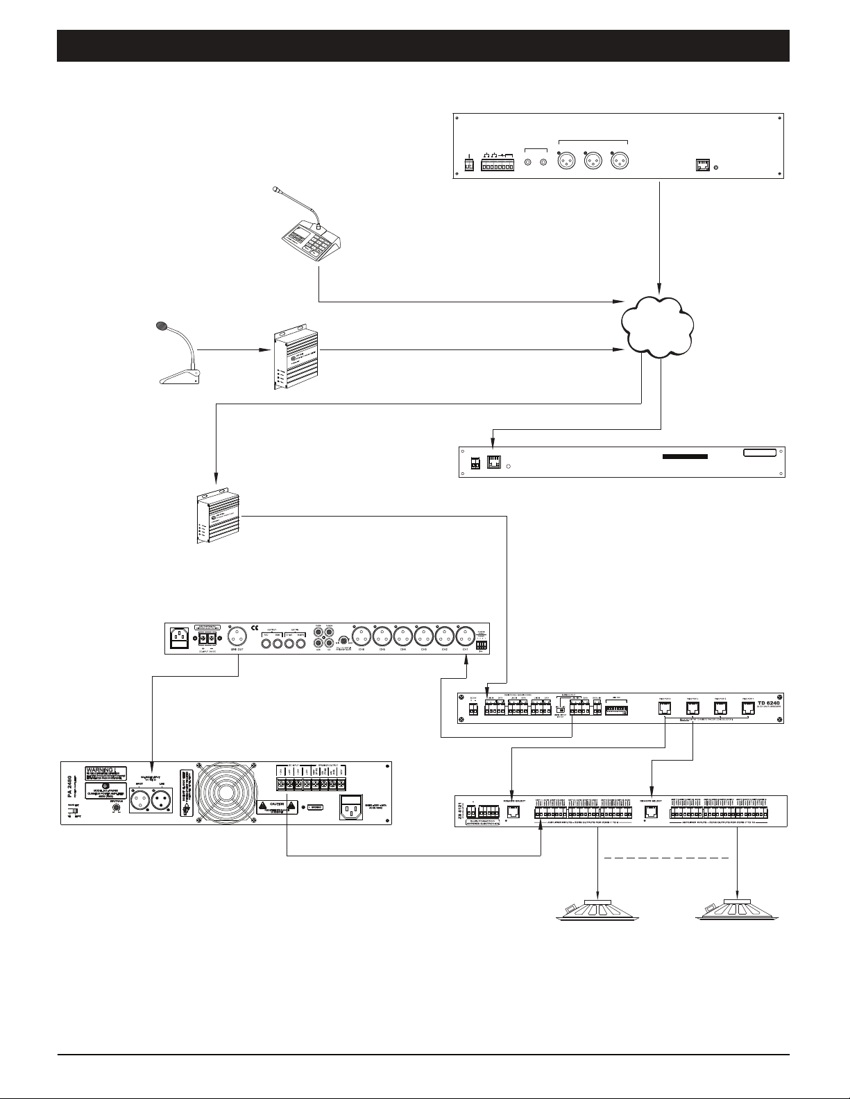
8. RELAY CONTACT
Triggering the front panel mic switch message or siren shall activate an internal relay. This ports provide a dry contact
which can be used to connect E/M overriding signal or to activate ALL CALL at speaker zone selector. The recommended
rating for the contact is 3A. In case higher rating is required, please use external relay or contactor to accommodate the
high current requirement.
7. REMOTE TRIGGER PORT FOR SIREN
External sensor device such as heat detector or fire alarm interface device can be connected to this unit to activate the
siren. The external device or switch must be voltage free to avoid damage to the unit. Two ways for the external switch to
turn On/Off the siren :
1) A <2s close-then-open to turn On; a <2s close-then-open to turn Off
2) A >2.5s close to turn On, an open to turn Off
6. EXTERNAL MESSAGE TRIGGER PORT
When this port is triggered by a voltage free contact, iEP1200 shall broadcast audio that applied to EXTERNAL
MESSAGE AUDIO INPUT (12).
10. HANDHELD MIC LEVEL CONTROL
This is to adjust the handheld mic volume. It is recommended that the setting is made during testing and commissioning
works.
11. SIREN OUTPUT LEVEL CONTROL
Adjust the siren output to an optimum level during testing and commission works.
12. EXTERNAL MESSAGE AUDIO INPUT
The external message playback signal shall be balanced line level. ( e.g: audio from MR1301 )
13. PRE-AMPLIFIER INPUT
User can connect a pre-amplifier mixer to this port and have the audio playback at AUDIO OUTPUT (14). Triggering
higher priority audio such as siren, handheld mic or external message shall override this pre-amplifier audio.
14. AUDIO OUTPUT
Siren, handheld mic paging, external message and pre-amplifier audio are broadcasted via this port to external audio ampli-
fier.
9. RS485 PORT
External controls or interface devices (e.g. PD1280 Paging Mic) shall be able to communicate with the unit via this port.
15. ETHERNET PORT
Connectivity to network switch. iEP1200 streaming siren, paging and external message to iPX5155 (Paging Client) via this
port.
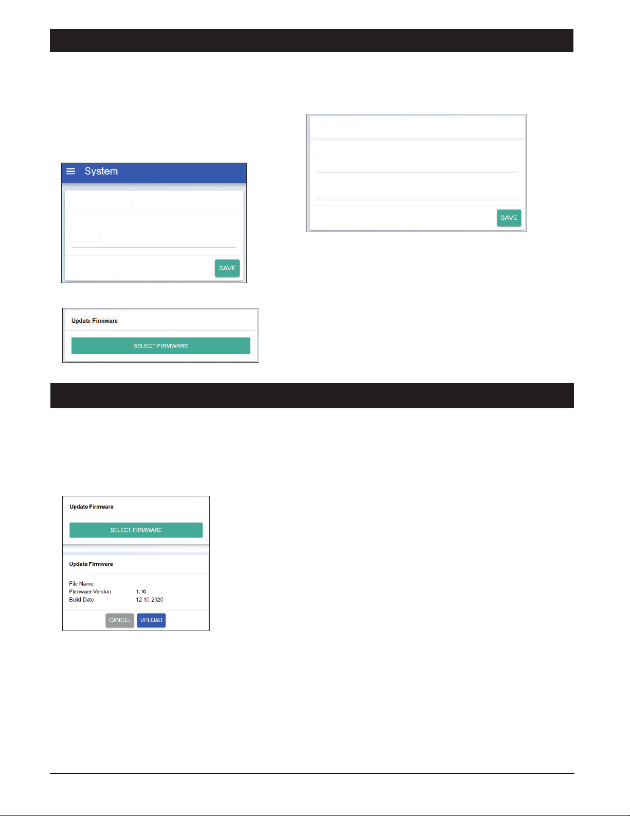
16. RESET SWITCH
Button to allow iEP1200 enters Bootloader mode or reset settings to factory default settings.
Bootloader mode: To enter this mode, hold the reset button until POWER, SERVER, and STATUS LEDs lit. Enter this
mode to do firmware updating if normal mode updating does not work. All iEP1200 settings remain intact in this mode.
Reset to factory default settings: Hold the reset button until POWER, SERVER, STATUS and STREAMING LEDs lit will
reset all iEP1200 settings to factory default settings.