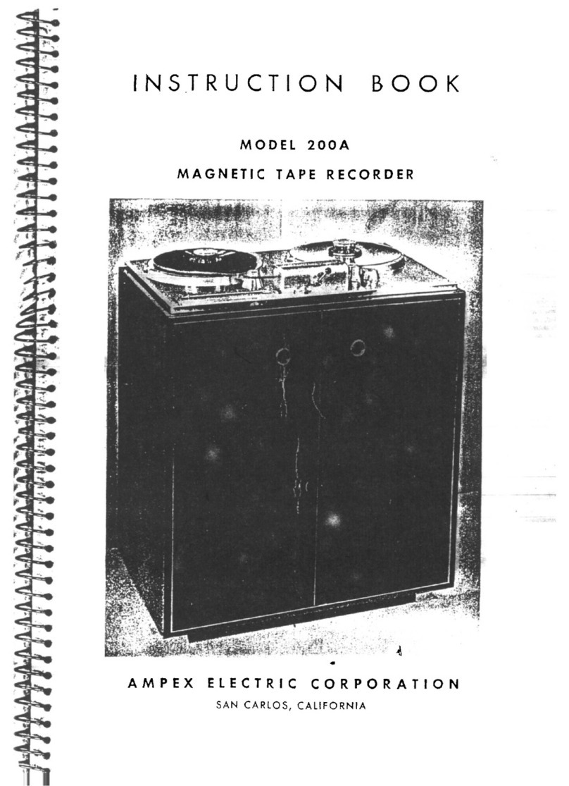
Ampex 350 User manual

www.SteamPoweredRadio.com
If You Didn't Get This From My Site,
Then It Was Stolen From...

www.SteamPoweredRadio.Com
I
I
I
I
I
I
I
I
I
I
I
I
I
I
I
I
I
I
I
32~T
I
CN
2
GE::T
I
ON
3
GE:::
TI
ON
4
350
-
6/1/53
I
NST.ALLA
TION
2. 1
Mount
i
ng
and
Inte
rconnecting
2
.2
A.
:::
.
Pow
er
~. 3
Output
2. 4
Input
2. 5
Phones
2. 6
.Remote
::ontrol
?• 7
60
:::;ycle
Amp
lifier
2. 3
Access
to
0onsole
:::ab
inet
2.
~
Access
to
Unders
i
de
of
Mechan
i
cal
Assemb
ly
:::ase
in
Tv"o
:::::ase ?
ortable
Z.
. 10
Cvera
ll
Perform
ance
Check
OPERATING
?RO:::EDURE
3. 1
Ree
l
Size
and
Reel
l<nobs
3. 2
Tape
Threading
3. 3
Hal
f
Track
Operation
3, 4
Power
3. 5
Sp
eed
Switches
3. 6
Tape
Mot
ion
3. 6. 1
Edit
in
g
and
Cueing
Techniques
TAP2
T~ANSPORT
MECHAN
I
SM
~. l
Major
Assemblies
4. 2
Tape
Tension
System
4. 2. l
Brake
Operation
4.
2.
2
Reel
Size
Switch
4. 3
Re
lay
Cperat
ion
4. 3, 1
?lay
4. 3. 2
Rewind
4. 3. 3
Fast
Forward
4 . 3. 4
Stop
4.
3.
5
::;afety
Interlocks
4, 4
Routine
Maintenance
4.
4.
1
::le
aning
~.
4. 2
Lubrication
4. 4. 3
Head
Demagnetization

www.SteamPoweredRadio.Com
I
I
I
I
I
I
I
I
I
I
I
I
I
I
I
I
I
I
I
SEC
TION
5
SEC
TI
ON
6
FIGURES
A, D, C
FIGURES
D,
E
FIGURE
O
FIGURE
1
FIGURE
2
FIGURE
3
FIGURE
4
FIGURE
5
FIGURE
6
FIGURE
7
FIGURE
8
FIGURE
9
FIGURE
10
FIGURE
11
FIGURE
12
FIGURE
13
FIGURE
14
350
-
6/1
/53
4. 5
4. 6
Adjustments
4 . 5. 1
Takeup
and
Rewind
Tension
4.
5. 2
Brake
Tension
4. 5. 3
Capstan
Idler
Pressure
Rep
l
acement
of
Parts
4. 6. 1
Packing
Precautions
for
Motors
4. 6. 2
Brake
Reconditioning
and
Replacement
ELECTRONIC
ASSEMBLY
5. 1
5.
2
'.5
. 3
5. 4
s.5
5. 6
Record
Amplifier
Playback
Amplifier
Bias
and
Erase
Osc
illator
VU
Me
ter
and
Monitoring
Power
Supply
E l
ectronic
Alignment
5.
6.
1
Alignment
and
Test
Equipment
s.6. 2
s.
6.
3
5. 6. 4
Requirements
General
Precautions
Playback
Circuit
Alignment
Erase
and
Reco
rd
C
ircuit
Al
i
gnment
PARTS
LIST
6. 1
Model
350
(Complete
Equipment)
6. 2
Tape
Transport
Mechanism
6. 3
Electronic
Assemb
ly
6. 4
Miscellaneous
Tape
Tension
System
Brake
Operation
Reel!
Hold
,....0own-
Knob
Electronic
Assembly
(7
l/2"-15")
E
lectr
onic
Assembly
(3
3/4
11 -7 1
/2"
)
Tape
Transport
Control
Circuits
Power
Supp
ly
Input
P l
ayback
Equalization
Curves
Record
Equalization
Curves
Electronic
Assemb
ly - F r
ont
Panel
Electronic
Assembly
-
Top
and
Rear
Electronic
Assembly
-
Bottom
Tape
Transport
Mechanism
-
Top
Tape
Transpo
rt
Mechanism
-
Bottom
Tape
Transport
Mechanism
-
Bottom-Fron
t
Tape
Transport
Mechanism
-
Bottom-Rear

www.SteamPoweredRadio.Com
I
I
I
I
I
I
I
I
I
I
I
I
I
I
I
I
I
I
I
SS
CTION
1
SPE
:!F
I
CA
TION3
The
Amp
ex
M
odel
350
mag
netic
tape
record
er
is
a
two
-
speed
audio
re
corder
designed
for
use
with
s
tand
ar
d 1
/4
inch
tape
. M
odel
350
is
avai
la
ble
in
cons
o 1
e,
two
-
case
po
rtab
l
e,
and
rack
-
moun
t s
ty
l
es,
all
with
either
full
or
half
track
heads
.
The
performance
specifications
and
characteristics
of
the
machine
a
re
as
follows
:
TAPE
SPEED
7- 1
/2
inche
s
per
second
an
d l 5
inches
per
second
or
3 -
3/4
inches
per
second
and
7-
1/2
inches
per
second.
FRE
r
uENC
Y
RESPONSE
S
peed
3-
3/4
11
7- 1
/2"
15
11
Response
~
2
db
50
to
7,500
cycles
+ 2
db
40
to
10,
000
cycles
~
4
db
30
to
15,
00
0
cycles
+ 2
db
30
to
1
5,000
cycles
SIGNAL
-
TO
-
NOISE
RAT
IO
Spee
d
3-
3/4
11
7- 1/ 2"
15
II
M
ax
.
Reco
rd
Leve
l
to
Unweighted
No
i
se
60
db
Fu
ll
Track
70
db
Ha
lf
Track
65
db
Fu
ll
Track
70
db
H
alf
Track
65
db
:?eak
R
ecord
L
evel
to
Unwe
i
gh
ted
No
i
se
50
db
Fu
ll
Track
60
db
Ha
lf
Track
55
db
Fu
ll
Track
60
db
Ha
lf
Track
55
db
The
peak
record
l
evel
is
defined
as
that
level
a t
which
the
ove
r a
ll
(
in
put
to
output
)
total
R MS
har
m
onic
distortion
does
not
exceed
3%
when
measured
on
a
400
cyc
le
tone
.
No
i
se
is
measured
when
erasing
a s i
gna
l of
peak
reco
rdi
ng
350
- 6/ 1
/53
l-1

www.SteamPoweredRadio.Com
level
in
the
absence
of
new
s i
gnal
.
as
we
ll
as
playback
amplifier
noise
.
cycles
are
measured
.
Thus.
bias
and
erase
noise
are
included
All
frequencies
betwe
e n
50
and
15,000
FLUTTER
AND
WO W
Speed
3-3/4
11
7
-1
/2
11
15
II
Flutter
and
·v
vow
• 3 %
•
25
%
• 2 %
The
flutter
and
wow
measurements
include
all
components
between
0
and
300
cycles
using
an
RMS
meter
ca
librated
to
read
the
peak
value
of
constant
amplitude
sine
wave
flutter
.
PLAY
ING
TI
ME
N
ITH
NARTB
10
- 1
/2
INCH
REELS
(2,400
feet
of
tape)
Speed
3-
3/4"
7
-1
/2"
15
II
START
I
NG
TIME:
Ha
lf
Track
4
hrs
. 16
min
.
2
hrs
. 8
min
.
64
min
.
Full
Track
2
hrs.
8
min
.
64
min
.
32
min
.
Instantaneous
(tape
accelerates
to
full
speed
in
less
than
1/ 10
second
.)
STOP
P
ING
TI
ME
: W
hen
playing
at
the
15
inches
per
second
speed,
the
t
ape
moves
less
than
two
inches
after
pressing
the
"Stop"
button
.
PLAY
BACK
TIMING
ACCURACY:
+ •
2%
or
+ 3. 6
seconds
in
a
thirt
y
minute
record
i
ng
.
RE
vV
IND
TI
ME
:
App
r
ox
imately
one
minute
for
the
fu
ll
2,
400
foot
NARTB
reel.
CONTROLS
:
The
tape
motion
is
contro
ll
ed
by
four
pushbuttons:
Start
,
Stop
,
Fast
Forward,
and
Rewind
. A
separate
Record
button
energizes
the
record
circuits,
which
will
drop
out
when
the
machine
is
stopped.
The
tape
sp
eed
is
changed
by
a M
otor
Speed
Switch
.
An
Equa
lization
Switc
h
changes
the
amp
-
lifier
equalization
appropriately
for
the
various
tape
speeds.
A
Reel
S
ize
switch
prov
ide
s
proper
tape
tension
for
either
the
NARTB
10-1
/2
inch
reel
or
the
R
MA
5
inch
and
7
inch
reels
.
1-2
350
-
12
/ 1
5/53
I
I
I
I
I
I
I
I
I
I
I
I
I
I
I
I
I
I
I

www.SteamPoweredRadio.Com
I
I
I
I
I
I
I
I
I
I
I
I
I
I
I
I
I
I
•
RECCRD
IN:?UT
: A
switch
allows
the
recorder
to
accommodate
either
micro
-
phone
l
evel
low
impedance
input
or
to
bridge
a
600
ohm
t 4
VU
line
,
balanced
or
unbalanced.
M
inus
80
dbm
at
the
microphone
input
wi
ll
produce
the
recom-
mended
record
level
.
!?L
AY
ZACK
OU
TPUT
: :?
lus
4 VU
out
p
ut
into
6
00
ohms
balanced
or u
nbalanced.
•:f
ill
feed
a
high
im
p
edance
amplifier
directly
with
approximately
one
volt
.
? L UG- IN
H.:Z
AD
HCUS
ING:
The
erase,
record,
and
pla
yb
ack
heads
are
con
-
tained
in a
single
plug
-
in
head
housing
.
MCN
IT
O:R
ING:
Independent
record
and
play
b
ack
systems
allow
the
ta
pe to
be
m
onitored
while
recordi
ng . A
phone
jack
is
provided
to
monitor
either
the
r
ecord
input
si
gn
al
before
or
during
recording,
or
the
output
si
g
nal
fro
m
th
e
p
la
yb
ack
head
w
hile
recordin
g or
during
playback
. A n
A-
B
switch
is
inco
rp
~
orated
in
ord
er
that
direc
t
com
p
arison
can
be
made
b
etween
the
ori
g
inal
pr
o-
gram
and
the
r
ecorded
pro
g
ram
.
The
same
switch
transfers
a 4
inch
VU
meter
for
level
com
p
arison
and
monitoring
.
The
VU
meter
is
also
u
sed
to
read
b
ias
and
erase
current
.
_=io
!ER
R2('U
IR
EMEN
TS:
The
half
and
full
track
machine
s r e
quir
e 2. 7 a
mp
ere
s
a t l 15
volts
A:::. M
achines
are
available
for
either
50
or
00
cycle
operation
.
Dl
iv1EN3I
ONS
AN
D
UE
IG
H
T:
R ac k M
ounted
:
(J
tandard
19
inch
wide
p
anel
with
commercial
notchin
g . )
T
ape
T
rans
p
ort:
15- 3
/4
inches
of
rack
s p
ace,
weight
50
lbs.
:2
lectronic
Assembly:
7
inches
of
rack
space
,
weight
18 l bs .
:?
ewer
S
upply:
3-1
/ 2
inches
of
rack
space,
weight
e
lbs
.
C
on
s
ole:
H
eight
•· 4C" (m
aximum}
Depth
-
28-1/2
11
(maximum}
·•
!
idth
- 24 - 1/ 211
J e ight - 1
68
pou
nd
s
3
50
-
6/
1
/53
1- 3

www.SteamPoweredRadio.Com
1- ~
'fwo
:ase
-
ortal:le
Tape
Transport
Cace
I-Iei
ght
-
15
-1/
2"
:.Jepth
-
17
11
.·'
idth
20
-
1/t;:"
.T
ei
g
ht
-
;:,9
)Ouads
Electronic
f,s
se
mb
ly
&
·?
ewer
:::;up:)
l
:r
::
ace
(with
extra
S:_Jace
for
m
ixer
or
ca'.)le
ctc
r a _:e)
ae
i
gh
t -
19
11
u
epth
-
13"
.'
idth
-
21"
i
ei
6
ht
-
(less
r.
:
i.xer)
42
r
ounds
I
I
I
I
I
I
I
I
I
I
I
I
I
I
I
I
I
350
- 6
/1/
:.'2
I
•

www.SteamPoweredRadio.Com
I
I
I
I
I
I
I
I
I
I
I
I
ii
I
I
I
I
I
I
....
.,::;TI
ON
2
2. 1 MC-UNT
ING
AND
INT
~H
CONN.:
::TING
.oefore
operating
the
recorder
,
re
ad
the
fo
llo
win
6
sectio
ns
on
I
1'f
•.,::'A. -
1
ATI-N
and
G.::::
.:,~AT
I
GN
.
::AUT
I - N:
.::>o
not
attem
:_:>
t
to
len
gthe
n i:he
head
c
abl
es
. Add
iti
on
al
ca ble
cap
a
city
wll
l
aff
ec
t
the
frequency
characteristics
.
A •
..::o
n
so
le 1\,
odels
:
:;
abinet
an
d
compo
ne
nts
are
p
ac!
ca
ged
separate
ly.
As
sembly
hardware
is
:n
ovided
.
Assem
ble
a s
follows:
(1)
Install
Tape
Tr
an
s·~ort
in
cabi
n
et
frame
and
secure
w
it
h 3 o
val
-
head
screws
a
nd
fini.shi.n
r;
w
ash
ers
.
(2)
Insert
2
spri
n
gs
in
ho
l
es
in
e l
ectro
nics
frame
of
cabinet
(3)
Install
'...
lec
-
tron
ic
Assem
bly
, com._,l
eti
ng
required
p
lu
g-
in
connections
between
it
and
the
tape
trans
.::,
ort
.
Use
fom·
k
nu
rled
nuts
to
secure
as
semb
ly
l:o
ca
b
in
et
. (
t;.
)
it
e-
move
back
p
anel
of
cabinet
an
d
install
.
?o
wer
.:;
upply
on
small
she
lf
a t
re
a r .
_,ecure
with
two
rou
nd
-h
ead
screws
.
,-;
lug
::
ewer
..:
up
p
ly
C
abl
e
int
o
.i:lectro
ni
c
Ass
embly
. (
5)
?
lu
g
in
pu
t,
output
,
an
d
AC
power
cables
into
rear
of
;~
le
ct
ro
n
ic
Assemb
ly
and
rep
la
c e
back
p
an
e l
of
cabinet
so
that
all
cables
run
freely
throu
gh
th
e
semi
-
circu
la
r
cuts
in
its
lo
wer
edge
.
n
✓
l::?0.R
TANT
:
The
back
of
th
e
co
n-
so
le
cabinet
m u
st
be
spaced
at
least
4
11
fro
,n
t
he
w
all
to
petrn
it
pro!_)er
ventilat
i
on
.
B.
Two
Ca
se
.?
or
ta
ble
M
od
els :
The
po
rtable
m
achine
is
shipped
in
a
ready
to
ope1.·ate
condition
,
e:;cep
t
for
the
co
nn
ections
of
inte
rc
onnectin
g
cab
le s.
To
operate
the
recorder
p
lace
the
Mech
anical
Ass
embly
Ca
se
to
the
ei
ght
of
the
Z
lectronic
Assemb
ly C
as
e.
Unlatch
and
remove
the
to
p
cover
an
d
ope
n
the
cab
le
access
do
or
on
the
left
side
of
the
Me
chanical
Ass
e
mb
ly
C
ase
. U
nlat
ch
an
d
remo
ve
the
remove
th
e
front
and
re
a r
covers
on
the
.C
l
ectro
nic
Assemb
ly
.::
as
e .
U
ncoil
the
int
e r
co
nn
ecti
ng
cables
from
be
hind
th
e
cab
le
acces
s
door
an
d
plug
the
m
into
m
atin
g
recept
acl
es
at
the
re
a r
of
the
Bl
ectro
ni
c
Assemb
ly.
Co
nn
ect
t
he
input,
output
,
and
A.:
:_)ower
to
the
rea
r
of
the
.":
lectronic
Assembly
.
350
-
12/
1
5/53
2- 1

www.SteamPoweredRadio.Com
C,
Rack
Mount
Mo
dels:
The
rack
mount
machine
should
be
mounted on a
standard
19 inch
relay
rack
with the Mec
hanical
Assembly
above the
main
El
ectronic
Panel,
The
Electronic
Pow
er
Supply
Panel
should
be
mounted
direct
ly above the Mec
hanical
Assembly
to
eliminate
the
possibility
of 60
cycle
field
from
entering
th
e
Electronic
A
ssembly
,
If two
Mo
del
350
Recorders
are
to be mounted on a
Standard
rack,
the following
placement
is
recommended
(starting
at
the
top of
the
rack):
1,
Install
a
spacer
panel
at
the top of the
rack
if
desired
.
2,
Install
below
thi
s panel the Mec
hanical
Assem
bly
for
machine
#
1,
3.
In
sta
ll
the El
ec
troni
c
Assemb
ly
for
mac
hin
e #1.
4,
Inst
a
ll
a
space
r
pane
l.
5.
Inst
a
ll
the Mec
hanical
Assemb
ly for
mac
hin
e
#2
,
6,
Install
the
Elec
tr
onic
Assembly
for
mac
hine
#2
,
7.
Install
a
space
r
pane
l,
8,
Inst
all
both P
ower
Supp
ly
Pane
ls
at
the
bottom
.
(the
cable
on the
power
supply
for
the
upper
record
er
will
have to
be
extended
in
length. Extension
cabl
e
#3814 is
ava
il
able
for
this
pu
rp
ose
.)
The
n
umbe
r s
set
off in
parentheses
in
the
fo
llowing t
ex
t a
re
re
fer-
ence numb
ers
that
refer
to the
Pa
rt
s L
ist
(Sec
tion
6) and the
figures
in
the
re
ar
of
thi
s
book
.
2. 2
AC
POWER:
Co
nn
ect
th
e
Power
Cabl
e,
Cata
log #241
3,
from
the AC Power Input
Co
nn
ec
tor (J409P) on the
Elec
tr
onics
Assemb
ly to a
source
of 115 Volt
AC
powe
r.
lMPORTANT:
This
machine
is
ava
il
able
for
eithe
r 50 or 60
cycle
o
per
a
ti
o
n.
The
power
lin
e
frequency
is
indicated
on
the
se
rial
number
plate
wh
ich
is lo-
cate
d on the Power
Sup
ply
Pane
l
for
r
ack
mount
mac
hines,
on
th
e
ex
te
rior
of
eac
h
case
in the
portab
le
mach
in
es,
and on the b
ack
of the
co
n
so
le
cabinet
.
2.
3 OUT
-P
UT
:
Refer
to
Figu
re
1
or
2.
P
lu
s 4
VU
, 600 ohm
lin
e output,
balanced
or unbalan
ced
,
is
a-
vailable
across
Terminals
2 and 3 of the Line Out
Co
nn
ector,
(J40
4P
). P
in
1
is the
chassis
grou
nd, H
unbalanced
output
is
des
ir
ed
, tie
either
s i
de
of
th
e
2
-2
350 -
4/
11/ 55
I
I
I
I
I
I
I
I
I
I
I
I
I
I
I
I
I
I
I

www.SteamPoweredRadio.Com
I
I
I
I
I
I
I
I
I
I
I
I
I
I
I
I
I
I
I
line
to
ground.
It
is
necessary
to
supp
ly 600
ohm
term
in
atio
n
to
this output
at
a
ll
ti
mes
in
order
to
ma
intain
correct
meter
calibration
while
recording
or
pl
aying
ba
ck
.
Therefore,
if
th
e o
utput
is
not
feeding
a
ter
m
in
ated
lin
e,
or
if
the
output is
not
connected,
such
as
on r
emote
pickups,
the Line O
ut
Termin
ation
Sw
it
ch, (S404),
must
be
switched
to
ON
.
B.
For
Connec
ti
on
to
H~h
Im_pedance
Am_pJ
ifier l9Put:
Connect
pin
3
of
th
e L
in
e Out Connecto
r,
(J
404P),
to
the
high
side
of
th
e
amp
lifi
er
in
put
.
Strap
pins
1 and 2
of
the
connector
and
connect
to th
e
grou
nd
side
of
the
amp
lifi
er
input.
The L
in
e
Ou
t
Terminat
i
on
Sw
it
ch
(
S4
04), must
be
le
ft
in
th
e
position
designated
ON
at
all
times,
as
exp
l
ained
in
A above.
2.4 INPUT:
Refer
to
Fi
gures
1 or 2 and
5.
The following
in
pu
ts
are p
ro
vi
d
ed
.
Any low
impedance
mic
rophone,
the
nom
in
al i
mpedance
of
which
is
in
th
e
range
of 30 to 250
ohms
can
be
plugged in
direc
tl
y. Connect
the
m
icr
ophone
to
pins
2 and 3
of
th
e Input
Connector,
J40
1S
).
Connect
cab
le
s
hi
e
ld
to
pin
1.
Place
the
In
put
Transfe
r
Sw
itc
h,
(S401),
to
the
MIC
position.
The
micro
rophone
in
put
t
ransformer
is
st
rapped
for
the
optimum
st
ep
up
for
a 150
to
250
ohm
so
urc
e. In
the
case
of
microphones
having
50
o
hm
s or
less
i
mpe
dan
ce,
6
db
addit
io
nal
ga
in
can
be
obta
ined
by
strappi
ng
th
e input
as
shown
in
Figure
5B.
This is not
usually
necessary,
however,
and
should
n
ot
be done
unless
in
su
ffici
ent
gain
is found to
ex
i
st
should
the
in-
put
be
fed
from
a
source
i
mpedance
grea
t
er
than
50
ohms.
IMPORTANT.
R402 and R403 will h
ave
to
be
chan
ged
to
24 o
hm
s and R401 and R404
to
68, 000
ohms
to
maintain
a flat r
espo
n
se
on
Ba
lan
ced
Br
i
dg
in
g when
the
transformer
is
st
rapped
for
50 ohm
source
impedance.
High
impedance
microphones
are
not
recommended
for
use
in
this
e-
qu
ipment.
In
gene
ra
l,
th
e
qual
ity
obt
ai
n
ab
le
from
high
imp
edan
ce
microphones
is not
satisfactory
for
profess
i
onal
work
. In
the
event
that
it
becomes
n
eces
-
sary
to
co
n
nect
a
hi
gh
impedance
mi
crophone
,
the
input
c
ir
cu
it wi
ll
ha
ve
to
be
re-wir
ed
as
shown
in
Figure
5A.
B. Briqgh1g_a
Bala
n
ced
Studio Line:
Conn
ect
a
balanced
lin
e
to
pins
2 and 3
of
the Input
Connector,
(J401
S)
.
P
in
1
is
g
round
.
Place
the
In
put
Transfer
Sw
i
tch,
(S401),
in
the
BALANCED
350 -
4/
11/55
2-3

www.SteamPoweredRadio.Com
BRIDGE
position
, Inp
ut
levels
of
minus
10
to
plus
10
VU
can
be
accommo-
dated
,
The
l
oad
placed
on
the
line is
approx
i
mately
300,000
ohms.
For
bridgin
g
higher
or
l
ower
level
lin
es
,
an
external
brid
ge
can
be
wired
in
the
li
ne
to
the
mach
ine. This would
consist
of
two
resistors,
th
e
va
l
ue
of
whi
ch
shou
ld
be
from
15,000
to
30,000
times
the
RMS
program
volt
-
age,
in
series
wi
th
each
side
of
the
line
. A 24
ohm
±
5%
resistor
should te
r-
minate
each
l
eg
of
the
output
side
of
the
two
bridging
resistors
, The junction
of
the
two 24
ohm
resistors
should
go
to
chassis
g
round.
The output
of
the
bridge
must
be
fed
to
the
microphone
input
of
the
record
er
, The input
of
the
recorder
may
be
connected
for
any
imp
edance
from
50 to 250
ohms.
C.
Briqgi)lKan
Unbalanced Sou
rce:
Connect
an
unbalanced
lin
e,
radio
tuner,
etc
. ,
to
pins 1 and 3
of
the
Input Connec
tor
(J401S),
Pin
1
is
the
g
round
side,
Pl
ace
the
In
put
Transfer
Sw
itch,
(S401),
in
the
UNBALANCED BRIDGE
position
,
This
connection
pro-
vides
a
60,000
ohm
bridging
input
for
any RMS
program
voltag
e
greater
than
1
/2
volt
, To
increase
the
input
impedance
above 60, 000 ohm, a
series
r e
sis
-
tan
ce
of
330, 000
ohms
can
be
wired
into
the
input pl
ug
in
ser
i
es
with pin 3
and
the
input
cab
le.
This
will
necessitate
an
input voltage
of
at
least
2-
1/2
volts
RMS.
It
is
important
that
this
resistor
be
physically
pl
aced
in
the cable
connector
that
pl
ugs
into
the
Recorder
Input
(J
401S)
in
order
that
th
e
cabl
e
capacity
be
on
the input side
of
the
res
i
stor,
2,5
PHONES:
Any
sens
i
tive
head
phones
can
be
plu
g
ged
in
the Phone
Jack
(J403
:::J
),
provided
for
monitoring
the
incoming
lin
e
or
playback
output,
2, 6
RE
MOTE CONTRO
L:
Refer
to
Figure
15.
The
operation
of
the
Tape
Transport
mechanism
can
be
remote
- con-
trolled
through
the
use
of
an
Ampex
Catalog
#5763
or
5763
-1
Remote
C
ontrol
Unit.
The
catalog
#5763
unit
is
supplied
in
a wooden
case
and
is
com
pl
e
tel
y
wired,
ready
to
plug into
the
Remote
Control
Connector, (J502S),
oo
th
e
front
of
the
Tape
Transport
C
ircuit
s
Assembly,
The
cata
l
og
#576
3-1
unit
is
mounted
on a
flat
plate
for
in
stallation
in
studio
conso
l
es,
and
is
not w
ir
e
d,
To
install,
wire
as
shown
in
Fi
gure
15, and plug into J502S.
NCTE:
2-4
W
henever
the
Remote
Contro
l
unit
is
n
ot
conne
ct
ed
, the Dummy
P
lu
g (P502P),
supplied
with
the
machine,
must
be
plu
gge
d
into J502S.
350 -
4/11/55
I
I
I
I
I
I
I
I
I
I
I
I
I
I
I
I
I
I
I

www.SteamPoweredRadio.Com
I
I
I
I
I
I
I
I
I
I
I
I
I
I
I
I
I
I
•
2. 7 6() : Y :::L.:: A
i\,i:i..lJ.i'I2
..
~:
(:..-~o
..
·
Drive
M
otor
Fow
e r )
The
Ampe,~
Model
37!:i
;?recisio;1
$·'.)
cycle
amplifier
or
i11odel
::::1A
..;l)eed
Lock
~quipment
can
be
plu~:,ed
in
directly
at
JSO3
.,
, I o
ofoer
con
-
nections
are
necessary
.
If
either
of
these
units
is
used
with
the
i
ecorder
,
the
.:ontrol
:::ircuits
Fuse
(F4J2
)
,.iust
be
i
ncreased
to
~
Amperes
.
I.:-o
not
remove
the
Dummy
Plug
(?503
P )
unless
one
of
these
units
is
to
be
conaectnC:
,
2.
~
A:::::::.::;.:;
TC
.:cr
1
.'.JCLi:
'.:A3Il'l.2T
:
:T
ARNING
: ~
efore
o;_Jen
i
n~
the
conso
le
or
~:iol"t
a b
le
cases,
disconnect
A'.:
~ew
er
.
:
om
·:i
lete
accessibility
for
inspection
or
service
is
!n-o
vided
rn
the
lop
and
bottom
of
the
.~
lect.:-onic
Assembly
and
0ottom
of
i:he
lVi
echanical
Assembly
.
0ee
:?i2ure
16
for
a;,
illustration
of
the
::
onsole
':abinet
o·)el1ed
for
full
accessibility
.
Cpen
ing
P1·ocedure:
1. .::1em
ove
the
four
cap
nuts
secu1·ing
~he :
le
ctronic
.Assembly
to
the
'.:
abinet
.
z.
?ull
the
.::Lectronic
Assembly
u~:,
until
t,1e
runners
a
re
[ree
of
the
slots
.
~e
-
insert
the
runners
in
the
short
slots
imroedia~ely
in
Crone
of
the
two
lov-1er
studs
,
3.
~e~.1ove
the
two
set
screws
holdine
the
chassis
:)ottor.1
!)late
.
!'he
bottom
;:,late
hinees
se,1a1·ate
at
the
rear
if
it
iz
desi1·ed
to
rer,1ove
the
p
late
con11,letely
,
~.
r.
Che
!ra1ne
on
which
the
Mechanic
al
Assem'~ly
is
r11oue1tecl
can
l)c
raised
90
degrees
or
more,
and
held
in
:>lace
l)y
a
slide
b~lt
on
the
lower
left
underside
of
the
frame
.
5.
The
:Po,
-
✓
er
-=:t•-::i
ply
is
accessi:...le
th1·ouuh
fo.e
rear
of
the
console
when
the
slidinc
panel
is
re1T•ovecl.
..;tand
Mech
a
,,ica
l
Assembly
'.:ase
on
end
as
s h
own
in
Y'igure
17
.
l.elease
the
latches
holding
the
ce,1ter
divisions
of
case
,
~:1en
to
apryroxi
-
nately
C:0
° .
Care
must
be
taken
to
ins
1ne
that
cables
can
pass
th,·ou3h
ca:,
le
corrnartment
into
the
main
cabine.
freely
.
2. !G CV1::C:ALl, ::?.2R:'?O~i
AN::_.
::··
..I.:::l': (
:leacl
Ject
ion
3
on
..:::?2IU,r_'l':.J\
1
befo
re
makinn
these
chec:~s
. )
350
-
i2/15/53
2- ~

www.SteamPoweredRadio.Com
The
fo
ll
owing
pr
o
cedure
is
recommended
for
checking
the
performance
of
this
recorder
at
the
time
of
installation
and
as
neccssar
y '
th
cr
ea
ft
er
.
A .
Ov
erall
Fr
equency
R
esponse
:
Thread
a
ne
w r
ee
l
of
tape
on
the
machine
. 2
qua
l
iza
ti
on
cu1·ves
for
the
Record
a nd
_:::,
l
ay
b
ack
Amp
li
fiers
a
re
shown
in
Figures
6
and
7•
.2nt
ire
ly
satisfactory
results
can
be
obt
a
in
ed
from
any
profess
i
onal
c;,t:a
li
ty
ta
pe.
l.
3-
3/4
and
7- 1/ 2
Inch
Respo
n
se
DUE
TO
THE
NATURZ
OF
THE
PRE
-
EMPHASIS
IN
TH
E
RZ:::ORD
~
IR~UIT
, TA
PE
SATURAT
I
ON
-
-TILL
OCCUR
AT
THE
!-IIGH
FRE
0
UENC
I
ES
UNLESS
THE
RESPONSE
::HECI<
IS
MADi.!:
AT
LEAST
20 DB
BELO
"/
!
NORMAL
OPER
ATI
NG
LZVZL
.
There
fore,
check
the
response
with
a
sensitive
meter
such
as
a H
ew
l
ett
-
Pack
ard
40
0
;:::;
connected
to
the
output
.
In
a
bsence
of
a
sensitive
meter
, a
standard
VU
M
eter
pre
-
ceded
by
a
flat
a
mp
lifier
with
at
l
east
20
db
gain
can
be
used
.
R
esponse
will
be
within
the
limits
indicated
in
the
Sp
ecifica
-
tions.
2.
15
In
ch
Response
Ma
ke
the
res
,onse
check
approximate
ly
10
db
be
l
ow
operat
-
i
1p
lev
e l
to
avoid
satur
ation
eff
e
cts
. R
esponse
wi
ll
be
within
the
limits
in
dicated
in
the
Sp
ec
ifications
.
.a
. C
verall
N
oise
Me
asurements
:
Overa
ll
w
ide
b;i.nd
noise
s
hould
be
measured
wi
th
a
Va
c
uum
Tube
V
olt
mete
r
such
as
Hew
l
ett
-
:!?
ackard
~o
o
;:::;
whi
le pl
aying
back
a
tape
that
has
pr
evious
ly
been
erased
on
the
m
achine
.
F
irst:
E
rase
the
tape
with
the
input
to
the
R
ecord
Amplifier
shorted
.
Rewi
nd
and
p
la
y
this
tap~
ba~k
. ?
erformanc
c
should
fa
ll
within
the
limits
specified
under
GIGNAL
-
TO
-
NCI:::;.i!:
RA
TI
O
in
S
ection
1. No
attem
pt
should
be
made
to
m e
asure
wide
band
noise
wh
ile
simultaneously
recordin
g
and
p
lay
in
6
back
as
leakage
of
the
1
00
re::
b
i.as
into
the
p
layback
head
may
inter
-
fe
re
with
the
measurement
.
2-6
350
-
6/
1
/53
I
I
I
I
I
I
I
I
I
I
I
I
I
I
I
I
I
I
I

www.SteamPoweredRadio.Com
I
I
I
I
I
I
I
I
I
I
I
I
I
I
I
I
I
I
I
1..,
,
Distortion:
O
verall
distortion
can
be
measured
by
connecting
any
standard
distortion
measurement
apparatus
across
the
ouput
.
The
readings
from
a
wave
analyzer
or
selective
frequency
distortion
meter
will
be
more
accurate
than
those
from
a
null
type
instrument
at
lower
distortion
levels,
Distortion
readings
are
somewhat
dependent
on
tape
, A
readin
g
of
1%
is
normal
at
operating
le
ve
l
whi
le
a
reading
of
3%
is
normal
at
6
db
above
operating
level
,
D,
Flutter
and
W
ow
:
F
lutter
and
W
ow
are
produced
by
periodic
irregularities
in
tape
sp
eed
and
appear
as
cyclic
frequency
deviations
in
recordi
ng
or
re
-
p
roduction,
They
can
be
measured
by
means
of
any
standard
flutter
bridge.
Variations
in
amplitude
as
indicated
on
level
measurements
do
not
constitute
flutter
and
are
entirely
due
to
tape
coating
variations
, R
eadings
will
be
well
under
• 2%
at
15
inch,
,
25
%
at
7-
1/2
inch
,
and
• 3%
at
3
-3
/4
inch
speed
,
F
or
more
infor
mation
on
alignment
or
performance
checking
,
refer
to
S
ec
ti
on
5,
350
-
6/
1
/5
3
2-7

www.SteamPoweredRadio.Com
I
I
I
I
I
I
I
I
I
I
I
I
I
I
I
I
I
I
I
.,:..::T
i
vN
3
..)PE..t:<A
TING
?~vCEDUc{
E.
The
Model
350
is
equipped
to
handle
either
the
NAI<TB
10-1/2"
reel
of
tape
or
the
smaller
RMA
5'
1
and
7"
sizes
.
The
Reel
~ize
.:>w
itch
(..>504)
adjusts
tape
tension
appropriately
for
the
reel
size
used
. un
console
or
po
rtable
machines,
position
the
small
reels
on
the
turntable
engaging
tht!
turntable
keys
.
For
the
la
r
ge
10-
1/2
11
reels
,
use
the
Editing
Knobs
(catalog
#1917)
that
have
been
provided
.
Rack
mount
machines
are
supplied
with
Hold-Down
l<nobs
(c
atalog
/1
4402)
for
both
small
and
large
reels
.
NJT£:
Always
use
reels
of
the
same
siz
e
on
both
turntables.
0pe
ration
with
one
large
and
one
small
re
e l
may
result
in
faulty
bra
king
action.
Thl!
,
4402
reel
hold
-
down
knob
(Figure
0)
works
in
th
e
following
manner
. A
re
movab
le
pin
in
the
bottom
surface
of
the
knob
engages
a
corresponding
hole
in
the
turntable
, A
collet
grips
the
turntab
le
shaft
wh
e n
th
e
top
of
the
knob
is
r
ota
ted
.
Two
spring-loaded
balls
hold
the
reel
to
the
tu
rntable
. A
pin
in
the
side
of
the
knob
drives
the
reel
.
The
knob
should
be
positioned
on
the
NA R
TB
reels
so
that
the
removable
pin
engages
one
of
the
tu
rntabl
e
holes
and
approximately
two
thirds
of
the
ball
is
exposed
above
the
reel.
The
knob
should
not
be
pushed
down
all
the
way
,
but
should
ride
above
the
turntable
.
Once
the
knob
is
positioned
correctly,
the
NAJ:<TB
reels
may
be
removed
without
removing
the
knobs
. 1vhen
using
th
e
knob
with
the
small
R
M\
r
eels
,
unscrew
th
e
removable
pin
.
The
knob
is
used
only
to
prevent
the
re
e l
fro
m
falling
off
the
turntable,
since
three
keys
in
the
turntable
drive
and
ce
nter
the
reel
.
Lock
the
knob
to
the
shaft,
avoidi
ng
excess
pressure
on
the
reel
which
could
distort
the
reel
flanges
.
3. 2 TAPl!..
THRE.ADING:
Thread
th
e
tape
as
indicated
in
Figure
1l . A
ll
new
factory
wound
r
ee
ls
should
be
unwou
nd
and
i.nspected
by
running
through
at
Fast
Forward
before
using
them
in
the
pl
ay
mode
of
operation,
New
tapes
are
usually
looped
to
the
hub
in
such
a
manner
that
th
e
tape
will
not
come
free
of
the
r
ee
l
at
the
e
nd
.
This
will
prevent
the
~a
f
ety
~wi
tch
(.::>501)
from
disengaging
th
e
.....
aosta
n
Idler
from
the
..:aps
tan
which
results
in
a
flat
being
worn
on
the
Ca'1!:>tan I
dler
/✓
heel
.
(Any
adhesive
material
accumulation
on
the
r
eel
hub
may
ab
o
keep
the
tap
e
fr
om
coming
free
at
the
end
of
the
reel,
and
should
ther
efo
r e
be
re-
moved
with
solvent
. )
350 -
12/
15/53
~
- I

www.SteamPoweredRadio.Com
3. 3
HALF
TRACK
OPERA
TION
:
The
handling
of
half
track
tapes
on
this
machine
is
accomplished
in
the
fo
ll
owing
manner.
The
tape
is
threaded
and
operated
as
described
under
TAPE
THREADING
and
TAPE
MOT
ION
.
However,
only
the
upper
half
of
the
tape
wi
ll
be
used
on
the
half
track
machine.
To
utilize
the
lower
half
of
the
tape,
the
full
reel
on
the
Takeup
Turntable
should
be
removed,
turned
over
and
placed
on
the
Tape
Supply
Turntable
upside
down.
P l
ace
an
empty
reel
on
the
Takeup
Turntable
.
Repeat
the
operation
as
performed
on
the
first
track
.
3. 4
POWER
:
Power
is
supplied
through
Power
Sw
itch
{S406),
which
must
be
turned
on
to
operate
the
Electronic
and
M
echanical
Assemblies
.
The
M
echanical
Assembly
and
Electronic
Assembly
are
individually
fused
by
the
3
ampere
Con
trol
~ircu
it
Fuse
(F402)
and
the
1
ampere
E l
ectronic
Fuse
(F401)
.
3. 5
SPEED
S H
IT
CHES
:
There
are
two
switches
associated
with
operating
s
peed
.
The
Tape
Speed
Swi
tch
(~503)
determines
the
speed
of
the
capstan
drive
motor,
and
the
E
qualization
Switc
h (
S402}
changes
the
equalization
in
the
amplifiers
appropriately
.
3.6
TAPE
MOTION:
The
tape
motion
is
contro
lled
by
means
of
four
pushbuttons
labelled
Rewind,
Fast
Forward
, S
top
and
Play
.
l . P
lay
or
Reco
rd:
The
tape
is
set
into
Play
motion
at
the
speed
selected
by
the
Tape
Spe
ed
Swi
tch
when
the
P l
ay
Button
(SSOS)
is
depressed
.
The
tape
must
be
complete
ly
stopped
before
starting
in
this
mode
.
To
change
from
P l
ay
mode
to
the
Record
mode
with
the
tape
in
motion,
press
the
Record
Button
{S
403)
on
the
E
lectroni
c
Assembly
.
2.
Stop
:
To
stop
the
ta
pe
while
it
is
moving
in
any
mode,
p~ess
the
Stop
Button
(S502).
The
machine
will
stop
automatically
if
the
tape
should
break
or
run
off
either
reel.
3- 2
350
-
12
/ 1
5/5
3
I
I
I
I
I
I
I
I
I
I
I
I
I
I
I
I
I
I
I

www.SteamPoweredRadio.Com
I
I
I
I
I
I
I
I
I
I
I
I
I
I
I
I
I
I
I
3. 6. 1
3.
Fast
Forward
:
The
lV.iod
el
350
can
Le
started
in
F
ast
F
orward
or
switched
to
F
ast
.Torw
ard
from
any
of
the
operating
modes
by
simply
depressin
g
the
I'ast
:?orw
ard
button
(,
.)506)
,
l;:.
Rewind:
The
Mode
l
350
can
be
started
in
newind
or
switched
to
-
Rewind
from
any
of
the
ope·.-ating
modes
by
s
im:)ly
der:,ress
-
ing
the
Rewind
button
(
S507
).
NCT.i:
:
In
using
either
the
Fas
t
Forward
01·
Rev,1
ind
mode
,
it
is
desira
b
le
to
remo
ve
the
tape
from
direct
contact
·:,1ith
the
heads
by
openin3
the
ga
te
of
the
Eead
Assembly
.
This
will
reduce
wear
on
the
heads
and
prevent
the
o:dde
coatin
g
on
the
tape
from
depositing
on
the
heads
and
ir.'l::_-:>ai
rin
g
their
p
erformance
.
ZDITIN
G
AND
::UEING
T:: ::::SN
I~
U.S:
Inde:dn
g
the
tape
as
in
editing
or
cueing
,
or
when
a~,proaching
the
end
of
the
reel
,
is
simplified
by
holding
dovm
a
com
bination
of
buttons
. T
ape
moti
on
can
be
reduced
to
a
slow
c1·ee?
by
holding
down
the
Fas
t
Fo
r...-,ard aP.d
Rew
ind
buttons
simultaneously
,
and
then
a
lter
nat
in
i
between
the
tw
'.)
to
con-
trol
tape
direction
. 1
hen
the
desired
p
oint
is
reac
hed,
the
Gto·,
bu
tton
should
be
held
down
until
the
other
buttons
are
re
leased
.
::::AUTI
ON
:
Never
press
the
Jtop
a
nd
Play
bu
ttons
i.n
rapid
sequence
when
the
tape
is
traveling
at
high
speed
in
i.he
~ew
ind
or
Fast
J?o
rwa1
·d
rnodes
.
This
will
almost
invaria
b
ly
break
the
tape
since
it
does
not
alloy,
sufficient
time
for
the
tape
to
stop
before
the
--:
apstan
Idler
locks
it
to
the
:apstan
.
3. 7
PLA
YBA'.:K:
To
play
back
a p
reviously
recorded
tape,
turn
the
ivieter
and
Cut
-
put
Switch
(
C405
),
to
the
extre
me
left
pos
i
tion
designated
?:_A
~3A:I<
-
i...:VE:
....
.
Then
start
the
tape
in
motion
as
indi
ca~ed
under
"?L
AY
. A ?
lay
:::
a
ck
L
evel
::ontro
l (3
438)
has
be
en
provided
on
the
front
pane
l
to
adjust
the
ta~e
lev
e l
to
plus
4 VU
out
put
. {Z
ero
on
the
VU
meter
. )
3. C R.12:::::0
RD
:
To
Tecord
a
new
program
oa
~:,reviously
reco-rded
ta_>e, o.
on
blank
tape,
turn
the
M
eter
and
Output
::;witch
(
C405
)
to
the
second
position
from
the
left
which
is
designated
nz
:ORD
-
;_,,..,;
vE
L.
Turn
the
~e
cord
Leve
l
:o
n-
trol
(
R4
09)
clockwise
un
til
the
le
vel
reads
O
(zero}
on
the
VU
.i\lieter
on
the
most
intense
pr
ogram
peaks
.
The
p
rogram
can
be
a
udibly
monitored
throu
ah
either
the
Phone
Jack
(J
~03C
),
or
the
.!..,
ine
Ot1t :
onnector
(J
404:?
)
350
- I 2/ I 5
'53
3- J
Other manuals for 350
1
Table of contents
Other Ampex Voice Recorder manuals