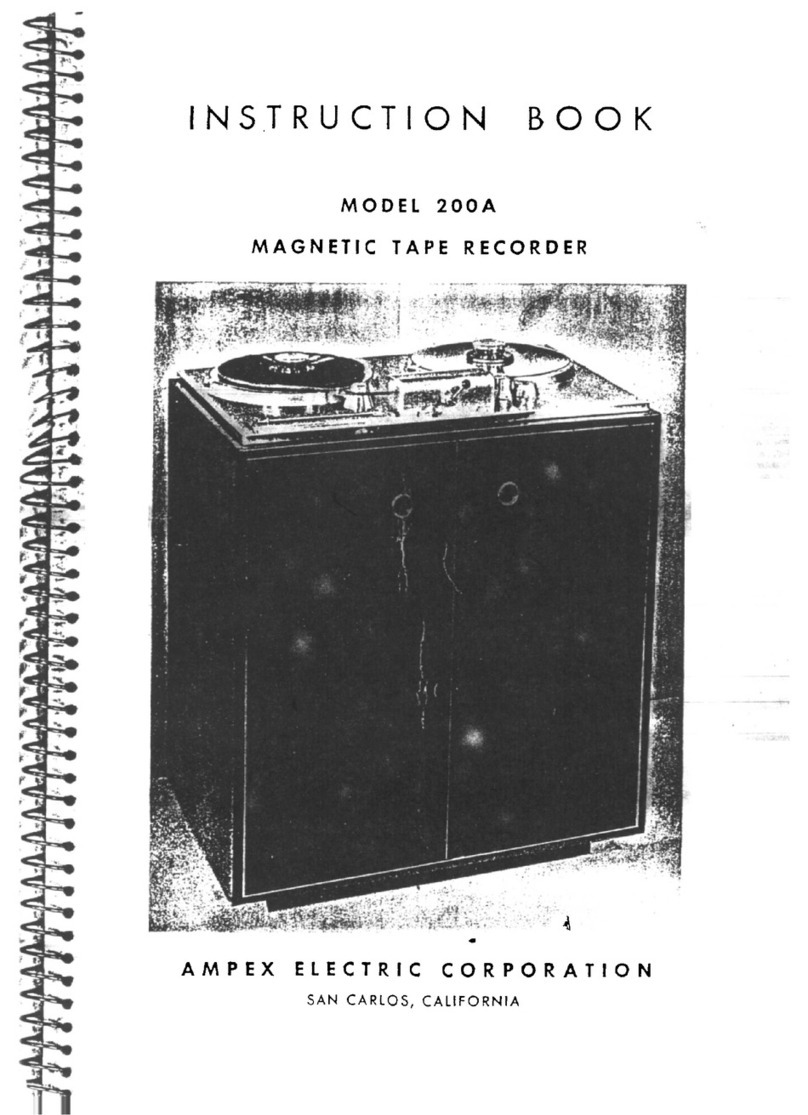
Ampex AG-445 B User manual

www.SteamPoweredRadio.Com
LIST
OF
PAGES
PAGE
CHANGE
IN
PAGE
CHANGE
IN
PAGE
CHANGE
IN
NUMBE~ EFFECT
~UMBH
EFFECT
NUMBEI
EFFECT
Title
8/7
1
6-4B
8/71
"A"
8/7
1
6-4C
8/71
6-4D
8/71
i -
xvi
1
/70
6-4E/F
8/7
1
6-5
8/71
Section
1
6-6
8/7
1
8
pages
6-7
8/71
6-8
8/71
Section
2 6
-1
0
8/7
1
8
pages
6-11
8/71
6-12
8/7
1
2-5/6
1/
70
6-13
1
/70
2-
7/8
1
/70
6-14
8/71
6-15
8/71
Section
3
6-16
8/71
6
pages
6
-1
7
8/7
1
6-18
8/71
Section
4
6-19
8/
71
54
pages
6-20
8/71
6-
21
8/7
1
4A-1
8/71
6- 22 1
/7
0
4B-5
1/70
6- 23
8/7
1
4B-8
1
/70
6-24
1/70
4B-9/
10 1
/70
6-25
8/7
1
4C-1
8/7
1 6- 26
1/70
4C- 2
1/70
j
6-27
8/71
4C-3
8/71
6-27A/B
8/7
1
4C-4
8/7
1 6-28 1
/70
4C-5
8/7
1 6-29
8/
71
4C-11
1
/70
6-
30
8/7
1
4C-12
1
/70
6-
31
1
/70
4E
- 2
8/71
6-
32
8/7
1
4E-3
8/7
1
6-33
1
/70
4E-4
8/7
1
6-34
8/71
4F
- 1 1
/7
0
6-35
8/7
1
4F
- 2 1
/7
0
6-36
8/71
6-37
8/71
Section
f 6- 38
8/7
1
9
pages
6-39
8/7
1
6-40
8/7
1
Section
E
6-41
8/71
45
pages
Section~
6
-1
8/7
1
16
pages
6-2
8/71
6-3
8/7
1
7B-1
8/71
6-4
8/71
7B-2
8/7
1
6-4A
8/7
1
7B-3
8/7
1
NOTE:
For
listing
of
separable
components
and
accessories,
see
pages
6-
2,
6-
3,
6-4
,
and
1-5
.
A
PAGE
CHANGE
IN
NUMBEF EFFECT
•
ISSUE:
August
1971
.,

www.SteamPoweredRadio.Com
4890301
COMMUNICATING WITH AMPEX
SERVICE
INFORMATION
AND
PARTS
FIELD
ENGINEERING BULLETIN SERVICE (See
note
below)
Ampex
provides
a
continuous
technical
support
program
for
its
products.
This
program
is
partially
implemented
through
field
engineering
bulletins,
which
are
published
by
the
Ampex
Technical
Support
Group.
Approved
modifications
,
information
on
special
tools
and
acces-
sories,
and
improved
operating
and
maintenance
techniques
are
typical
of
the
information
distributed
in
these
bulletins.
If
the
installation
of
your
system
or
accessory
was
supervised
by
an
Ampex
Field
engineer,
y
ou
will
be
sent
these
bulletins
automatically
.
If
this
is
not
the
case,
contact
the
nearest
Ampex
field
office
or
write
to:
Ampex
Corporation
Audio
Technical
Support
Group
401
Broadway
Redwood
City
,
California
94063
USA
SERVICE
AND
REPLACEMENT
PARTS
(See
note
below)
For
service
and
replacement
parts,
contact
your
nearest
Ampex
field
office.
If
the
installa-
tion
of
yo
ur
system
or
accessory
was
supervised
by
an
Ampex
field
engineer,
yo
u
will
be
sent
information
regarding
the
location
of
the
nearest
field
office
.
Alternatively,
write
to
the
Technical
Support
Group
at
the
address
shown
above.
ii
NOTE
In
order
for
the
technical
support
program
to
function
properly,
the
user
must
ensure
that
his
communication
is
addressed
to
the
proper
depart-
ment,
and
that
it
includes
the
following
informa-
tion,
most
of
which
can
be
obtained
from
the
system
identification
nameplate
on
the
equipment.
1.
System
name
2.
Model
number
(including
revision
number)
3.
System
number
4.
Serial
number
5.
Power
requirements
6.
System
modifications
and
special
accessories
7.
Date
of
purchase
8.
Name
and
address
of
yo
ur
organization
9.
Job
function
to
which
communication
should
be
addressed
10.
Ph
ysica
l
location
of
equipment
AMPEX
•
•
•

www.SteamPoweredRadio.Com
•
•
•
4890301
COMMUNICATING WITH AMPEX
INSTRUCTION
MANUAL
CHANGES
Another
part
of
the
Ampex
program
of
technica
l
support
for
its
products
is
the
continuous
revision
and
modification
of
instruction
manuals
as
the
eq
u
ipment
is
improved
or
modified
. In
order
to
ensure
that
you
always
receive
this
information,
write
to:
Ampex
Corporation
Audio/Video
Technica
l
Publications
Department
401
Broadway
Redwood
City,
California
94063
USA
NOTE
In
order
to
be
sure
that
you
always
receive
information
applicable
to
your
equipment,
please
include
the
following
information
when
you
write
to
us
:
1.
System
name
2. Model
number
(including
revision
number)
3.
Serial
number
4.
Power
requirements
5.
System
modifications
and
special
accessor
i
es
6.
Approximate
date
of
purchase
7.
Name
and
address
of
your
organization
8.
Job
function
to
which
communication
should
be
addressed
AMPEX
iii

www.SteamPoweredRadio.Com
4890301
SAFETY
&
FIRST
AID
Because
personnel
wo
rki
ng
with
electronic equipment
are
exposed
to
the hazard
of
high voltage,
it
is imperative
that
all safety regulations be consistently observed, and
that
each individual
has
a clear understanding
of
basic First
Aid
methods.
-::
The
following
typical
hazards must be avoided
at
all times:
POWER.
1
Do
not
attempt
adjustment
of
unprotected
ci
r
cuit
controls,
or
lead dress
while
the
power
is ON.
2
Do
not
change heavily loaded
or
overheated compo- 1
nents
without
due precaution
to
avoid burns. - ,
3
Do
not
assume
that
no dangerous voltage is present
when the power is
OFF
. Charged capacitors may retain
dangerous voltages
for
long periods, and should be dis-
charged through a suitable resistor before
any
circuit
po
int
sare touched.
4
At
all times avoid placing any parts
of
the
body
in
.,,;.,
betw"n
grn,nd
and
d,o,;t
po;nts,
wheth"
o,
~~@
not
power is ON.
~
,,...-
1.
• ,
~
&~-~
5
Do
not
assume
that
solid-state circuits and semiconduc-
..L
~
,
tor
cases
carry
only
low
voltages.
-:
/ \ ·
Y0
8633
For
their
own
protection, and
the
protection
of
others, all
electronic personnel should become
thoroughly
familiar
with
the
approved
First
Aid
treatment of burns and shock.
There are three principal degrees
of
burns, recognizable
as
follows:
1. A
first
degree
burn
reddens the skin
2.
A second degree
burn
blisters the skin
3. A
third
degree
burn
chars
the
flesh and frequently
places the
victim
in
a state
of
shock accompanied
by
respiratory paralysi
s.
Respiratory paralysis
in
the
victim
can cause death
wi
th
in
seconds,
by
suffocation.
For
this
reason
it
is imperative
that
the
approved method
of
artificial
respiration be
in
itiated
immediately and continued
until
th
e
victim's
breathing is
normal.
A muscular
spasm
or
unconsciousness may render
the
victim
unable
to
free himself
of
the
electric power.
If
this
is the
case,
turn
the
power
OFF
immediately.
DO
NOT
TOUCH
HIM,
OR
YOU
MAY
SHARE HIS
PREDICAMENT.
If
the
power cannot be turned
OFF
immediately, very
carefully
loop
a
dry
rope, article
of
clothing, length
of
strong
cloth,
or
a rolled-up newspaper around the
victim
and
pull
him
free
of
the
power. Carefully avoid touching
him
or
his clothing.
The
moment
he is clear
of
the
power, place
him
in a
reclining position, cover
him
with
a blanket
(or
news-
papers)
to
keep
him
warm, and begin artificial respiration.
At
the
first
opportunity,
enlist help
in
the
summoning
of
a
doctor.
If
a
doctor
cannot
be summoned, transport the
victim
to
the
doctor,
infirmary,
e>r
hospital. Be sure
that
the
victim
is
kept
well covered and warm
while
awaiting
professional aid and treatment.
iv
AMPEX
•
•
•

www.SteamPoweredRadio.Com
•
•
•
TABLE
OF
CONTENTS
Paragraph
Section
1.
1.1
1.2
1.3
1.4
1.5
1.6
1.7
Section
2.
2.1
2.1.1
2.1.
2
2.1.3
2.2
2.3
2.4
2.5
2.5.1
2.5.2
2.5.3
2.
5.4
2. 6
2. 7
2.7.1
2.7.2
2.7.3
2.
7.4
2.8
2.9
Section
3.
3.1
3.
1.1
3.1.
2
3.
1.3
3.2
3.2.1
3.2.2
3.2.3
3.2
. 4
3.2.5
3.3
3.3
. 1
3.3.2
3. 4
3.5
DESCRIPTION
General.
Tape
Transport
Record/Reproduce
Electronic
Unit.
Reproduce
Electronic
Module .
Head
Assembly
Optional
Equipment
Specifications
INSTALLATION
Unpacking.
General
.
Console-Mounted
Equipment.
Unmounted
and
Portable
Equipment.
Mounting
Units
Console
Front
Panel
Removal.
Interconnecting
Units.
Connecting
Signal
Lines
Connectors
.
Signal
Input
Connections.
Signal
Output
Connections
.
Restrapping
Output .
Connecting
Power
.
Installing
Accessories
or
Dummy
Plugs
Input
Transformer
or
Microphone
Preamplifier
Remote
Cont
r ol
Unit
Console
Rear
Covers
.
Scrape-Flutter
Idler
Checking
Cables
and
Components
Initial
Lubrication
.
OPERA
TING INSTRUCTIONS
Operating
Controls
and
Indicators
.
Tape
Transport
.
Record/Reproduce
Electronic
Unit
.
Reproduce
Electronic
Module
Pre
-
Operating
Procedures
Applying
Power
Selecting
Tape
Speed
.
Selecting
Reel
Hub
Size
.
Threading
Tape
Monitoring
Facilities
.
Recording
Witho
ut
Sel-Sync*
With
Sel-Sync*.
Reproducing.
Fast-Winding
.
*
Registered,
Ampex
Corporation
JAN.
1970
AMPEX
)1890301
1-1
1-1
1-2
1-2
1
-4
1
-4
1-4
2-1
2-1
2-1
2-2
2-2
2-2
2-2
2-2
2-2
2-2
2-4
2-4
2-4
2-4
2-4
2-4
2-4
2-5
2-5
2-5
3-1
3
-1
3-2
3-2
3-4
3-4
3-4
3-4
3-4
3-4
3-4
3-4
3-4
3-5
3-5
V

www.SteamPoweredRadio.Com
4890301
3.6
Editing.
.
3-6
Section
4.
MAINTENANCE •
4 .1
Introduction
4-1
4.2
Contents
. .
4-1
PART
A.
CONVERSION
4A
. l
Turntable
Repositioning
.
4A-l
4A.2
Tape-Width
Conversion
4A-l
4A
.
2.1
General.
4A-l
4A.2.2
Rotating
Tape
Guides.
4A-l
4A.2.3
Changing
Heads
4A-2
4A.2.4
Changing
Head
Cable
Box
.
4A-2
4A.3
Scrape-Flutter
Idler
Addition.
4A-2
4A.4
Channel
Addition
4A-3
4A.4.l
General
.
4A-3
4A .
4.2
Record/Reproduce
Unit
Installation
4A-3
4A.4.3
Reproduce
Module
Installation.
4A-4
4A.5
Conso
le
Rear
Cover
Installation
4A-4
4A.6
Record
and
Reproduce
Conversion
4A-4
PART
B.
PREVENTIVE
MAINTENANCE
4B.l
Eighth-Hour
Cleaning
.
4B-l
4B.
l.
l
Heads
4B-l
4B.l.2
Tape
Guide
Elements.
4B-l
•
4B
.
l.3
Scrape-Flutter
Idler
.
4B-l
4B.2
Eighth-Hour
Demagnetizing
4B-l
4B.3
Lubricating
. .
4B-2
4B.3.l
General.
4B-2
4B.3.2
Drive
Motor
Initial
Lubrication
4B-2
4B.3.3
Motor/Idler
Three-Month
Lubrication
4B-2
4B.3.4
Idler
Yearly
Lubrication
4B-3
4B. 4
Performance
Checkoots
4B-3
4B.4.l
General.
.
4B-3
4B.4.2
Test
Equipment
.
4B-3
4B.4.3
Test
Conditions
4B-4
4B.4.4
Frequency
Response
Checkout.
4B-4
4B.4.5
Overall
Signal-to-Noise
Check
4B-6
4B.
4.
6
Overall
Distortion
Check
.
4B-7
4B.4.7
Flutter
Check
.
4B-7
PARTC.
ADJUSTMENT AND ALIGNMENT
4C.l
General
.
4C-l
4C.2
Tape
Transport
Adjustments
.
4C-l
4C.2
. l
Test
Equipment
.
4C-
l
4C.2.2
Different
Tape
Sizes
.
4C-l
4C.2.3
Tape
Tension
4C-1
4C.2.4
Brakes
4C-3
4C.
2.5
Capstan
Idler
4C-5
•
4C.2
.6
Tape
Lifter
4C-5
AMPEX
JAN.
1970

www.SteamPoweredRadio.Com
•
•
•
4C.3
4C.3.
l
4C.3.2
4C.3.3
4C.3.4
4C.3.5
4C.
3.
6
4C.3.7
4C.3.8
4C.3.9
4C.
3.10
4C. 4
4C.
4.1
4C.
4.
2
4C.
4.3
4C.4.4
4D.1
4D.2
4D.2.1
4D.
2.2
4D.2.3
4D.3
40.4
4D.4
. l
4D.4
. 2
40.5
4E.1
4E.2
4E.
2.1
4E.2.2
4E.2.3
4E.2.4
4E.3
4E.3.1
4E
.
3.
2
4E.3.3
4E.4
4E.4.l
4E.4.2
4E.4
. 3
4E.4.4
4E.4.5
4E.4
. 6
4E.4.7
4E.4.8
4E.4.9
Electronic
Alignment.
. .
Standard
Test
Tapes
Test
Equipment
. .
Test
Conditions
. .
Alignment
Procedures
Introduction
.
Power
Supply . . . . . . .
Reproduce-Head
Azimuth
..
Reproduce/Record
Alignment
Record-Head
Azimuth.
. . .
Low-Frequency
Reproduce
Equalization.
Record
Equalization
Sel-Sync
*
Adjustments
.
Test
Equipment
. .
Test
Conditions
. .
Sel-Sync*
Level
Adjustment
.
Sel-Sync*
Bias
Trap
Adjustment
.
PART
D.
HEAD MAINTENANCE
General
......
.
Adjusting
Head
Height
. . . .
Record/Reproduce
Heads
Quarter-Track
Record/Reproduce
Heads
Erase
Heads
. . . . . . .
Ad)lsting
Tape
Wrap
and
Zenith
.
Changing
Head
Stacks
. . . . .
Record
or
Reproduce
Stack
Erase
Head
Stack
Tape
Skew
Checkout
. . . . . .
PART
E.
TRANSPORT MAINTENANCE
General
Servicing
Units
Brake
Bands
.
Solenoids
. .
Relays
Capstan
Idler
Head-Cable
and
Power-Supply
Boxes
Replacement.
Head
-Cable
Box
. . . .
Power
Supply
Removal
.
Power
Supply
Installation
Takeup
and
Rewind
Assemblies
General
. .
...
. .
Replacing
Takeup
or
Rewind
Assembly
Reel
Drive
Plate
Replacement
.
Turntable
Pad
Replacement
Brake
Assembly
Removal
Brake
Band
Replacement
Brake
Solenoids
Replacement
Brake
Installation
and
Adjustment
Motor
Capacitor
Replacement
..
*
Registered,
Ampex
Corporation
JAN.
1970
AMPEX
\
4890301
4C-6
4C-6
4C-6
4C-7
4C-7
4C-7
4C-7
4C-8
4C-10
4C-11
4C-ll
4C-12
4C-12
4C-12
4C-12
4C-13
4D-l
40-1
4D-l
4D-2
4D-2
4D-2
40-2
4D-2
40-3
4D-3
4E-1
4E-1
4E-1
·
4E-l
4E-l
4E-2
4E-2
4E-2
4E-2
4E-2
4E-2
4E-2
4E-2
4E-3
4E-3
4E-3
4E-3
4E-3
4E-4
4E-4
vii

www.SteamPoweredRadio.Com
4890301
viii
4E.5
4E.5.1
4E.5
. 2
4E.5.3
4E
.
5.4
4E.6
4E.
6
.1
4E.6.
2
4E.6.3
4E.6
. 4
4E.
6.5
4E.6.6
4E.7
4E.
7.1
4E
.
7.2
4E.
7.3
4E.7.4
4E.
7.5
4E.8
4E.8.1
4E.8.2
4E.8.3
4E.8.4
4E.8.5
4E.9
4E.9.1
4E
.
9.2
4E.9.3
4E.10
4E.ll
4E.11.1
4E.ll.2
4E.11
. 3
4E.11.4
4E.11.5
4E.11.6
4E.11.7
4.
E.11.8
4E.ll.9
4E
.
11.10
4E.11.11
4E.ll.12
4F.1
4F.2
4F.3
4F.3.1
4F.3.2
4F.4
4F.5
4F.6
Drive
Motor.
. .
Lubrication
Fan
and
Flywheel
Replacement.
Drive
Motor
Replacement
.
Motor
Capacitor
Replacement
Reel
Idler
Tape
Guide
Replacement
Pulley
Replacement.
Idler
Tension
Adjustment
Arm
Assembly
Replacement.
Reel
Idler
Replacement
.
Ball
Bearing
Replacement
.
Takeup
Tension
Arm
.
Arm
Spring
Adjustment
.
Safety
Switch
Adjustment
Tape
Guide
and
Hook
Replacement
Tension
Spring
Replacement
.
Takeup
Tension
Arm
Replacement
Capstan
Idler
Lubrication
and
Adjustment
Parts
Not
Removable
.
Idler
Positioning
.
Idler
Replacement
Capstan
Solenoid
Replacement
.
Tape
Lifter
Adjustment
Procedure
Solenoid
Replacement
Tape
Lifter
Replacement
Safety
Switch
. .
Servicing
Procedures
General
.
Control
Box
Bottom
Cover
Removal
Control
Box
Removal
.
Power
Checks
.
Relay
Actuation
Check
.
Solenoid
Actuation
Check
Drive
Motor
Check
.
Takeup
Motor
Check
Rewind
Motor
Check
Power
Lamp
Replacement
.
Switch
Replacement
Record
Circuit
Check.
.
PART
F.
ELECTRONIC CORRECTIVE MAINTENANCE
Genera
l
Extender
Boards
Use.
.
Input
Power
and
Indicators
Check
Recorder/Reproducer.
Reproducer
(only)
Record
Relay
Check
Power
Supply
Check
Bias
Check
AMPEX
4E
-5
4E-5
4.
E-5
4E-5
4E-5
4.
E-5
4E-5
4E-5
4.
E-6
4E-6
4E-6
4E-6
4E-7
4E
-7
4E-7
4E-7
4E-7
4E-7
4E-8
4E-8
4E-8
4E-8
4E-8
4E-8
4E-9
4E-9
4E-9
4E-10
4E-10
4E-10
4E-10
4E-10
4E-ll
4.
E-11
4E-12
4E-12
4E-15
4E-15
4E-16
4E-17
4E-
17
4E-17
4F-1
4F-1
4F-1
4F-1
4F-2
4F-2
4F-3
4F-3
JAN
. 1970
•
•
•

www.SteamPoweredRadio.Com
•
•
•
4F.
7
4F.
7.1
4F.7.2
4F.
7.3
4F.8
4F.9
4F
.9.1
4F.9.
2
4F
.9.
3
4F.10
Section
5.
5.1
5.1.1
5.1.2
5.1.3
5.
1.
4
5.1.5
5.1.6
5.1.
7
5.1.
8
5.2
5.2.1
5.2.2
5.2.3
5.2.4
5.2.5
Section
6.
6.
1
Section
7.
7A.1
7A.2
7A.
2.1
7A.2.
2
7A.2.3
7B.1
7B.2
7B.3
7B.4
7C.1
Record/Reproduce
Check.
General
Record
Check
.
Reproduce
Check.
Rept'oduce
Check
.
Parts
Replacement
Indicator
Lamps
.
Circuit
Board
Components
Other
Components
Response
Curve
Check
THEORY
OF
OPERATION
Tape
Transport
. . . . . . . . . .
General
..........
.
Tape
Supply
and
Takeup
Systems.
Tape
Drive
System
..
Reel
Idler
.....
.
Takeup
Tension
Arm
.
Tape
Lifter
. . . .
Control
Circuit
. .
Tape
Scrape-
Flutter
Electronic
Circuits
. . .
Power
Supply
. . .
Bias
Oscillator
and
Amplifier
Circuits
.
Record
Amplifier
Circuit
. .
Reproduce
Amplifier
Circuit
Sel-Sync*
Circuit
. . . . .
PARTS
LISTS AND DRAWINGS (See
List
of
Illustrations)
Introduction
• . . . . . . . . . . . . . . . . . . .
MODIFICATION PROCEDURES
PART
A.
TAPE
TRANSPORT MODE ALTERATIONS
General
.. ..
.
...
....
.
.......
.
Modification
Procedures
. . . . . . . . . . . . . . . . . . . . . . .
Modification
to
Enter
any
Other
Mode
Directly
from
the
Record
Mode
Modification
to
Defeat
all,
or
any,
of
the
Edit
Functions
. . . . .
Modification
to
Enter
the
PLAY/EDIT
Mode
by
pressing
the
EDIT
Pushbutton
(when
Tape
is
Stopped)
Even
When
the
Safety
Switch
is
Open
..
........
.
...............
.
PART
B.
EXTERNAL
MOTOR DRIVE
AMPLIFIER
ADDITION
General
. . . . . . . . . . . .
Internal
Wiring
. . . . . . . . .
Connecting
Motor
Drive
Amplifier.
Preparing
Dummy
Plug
. . . . .
PART
C .
SEL-SYNC*
REMOTE
CONTROL
Description
. . . .
*
Registered,
Ampex
Corporation
JAN,
1970
AMPEX
489.0301
4F-4
4F-4
4F-4
4F-4
4F-4
4F-5
4F-5
4F-5
4F-5
4F-5
5-1
5-1
5-1
5-2
5-2
5-2
5-3
5-3
5-6
5-6
5-6
5-7
5-7
5-8
5-9
6-1
7A-
1
7A-1
7A-1
7A-1
7A-2
7B-1
7B-1
7B-2
7B-2
7C-1
ix

www.SteamPoweredRadio.Com
4890301
7C.2
Switching
Unit.
7C.2.
l
General
.
7C.2.2
Mounting
7C.
2.
3
Connecting
7C.3
Control
Unit
7C.3
. 1
General.
7C.
3.
2
Mounting
7C.3.3
Connecting
7C.4
Remote
Operation
.
7C.4.l
Recording
7C.
4. 2
Reproducing
.
7C.4.3
Fast-Winding
7C.4.
4
Edit
Mode
7C.5
Ad)lstments
7C.5.l
General.
7C.5.2
Sel-Sync*
Level
Adjustment.
7C.5
. 3
Sel-Sync*
Bias
Trap
Adjustment.
X
AMPEX
7C-l
7C-l
7C-1
7C-1
7C-2
7C-2
7C-2
7C-2
7C-2
7C-2
7C-3
7C-4
7C-4
7C-4
7C-4
7C-4
7C-4
*
Registered,
Ampex
Corporation
JAN.
1970
•
•
•

www.SteamPoweredRadio.Com
4890301
LIST
OF
ILLUSTRATIONS
•
Figure
TITLE
Page
Frontispiece
Ampex
Model
AG-440B
Recorder/Repr6ducer.
1-1
Tape
Transport
.
1-2
1-2
Record/Reproduce
Unit
1-2
1-3
Printed
Circuit
Boards
1-4
1-4
Reproduce
Electronic
Module .
1-4
2-1
Mounting
Dimensions
2- 2
2-2
Front
Panel
Mounting
Details
.
2-2
2-3
Tape
Transport
Connector
Panel.
2-3
2-4
Record/Reproduce
Unit
(Rear)
2-3
2-5
Record
and
Reproduce
Modules
2-5
3-1
Controls
and
Indicators.
3-3
3-2
Tape
Threading
Path
3-3
•
4A-1
Head
Assembly
(Overlay
Removed)
4A-2
4A-2
Head
Cable
Box
. .
4A-2
4A-3
Scrape-Flutter
Idlers
Installed
4A-3
4A-4
Record/Reproduce
Unit
Supports
4A-4
4B-1
Noise
Filter
Schematic
.
4B-6
4B-2
ASA
"A"
-Curve
Filter
Schematic
.
4B-6
4C-1
Tape
Tension
Adjustments
4C-2
4C-2
Brake
Adjustments
4C-3
4C-3
Capstan
Idler
Adjustment.
4C-4
4C-4
Capstan
Idler
Force
Measurement.
4C-5
4C-5
Power
Supply Box
Interior
4C-7
4C-6
Head
Azimuth
Adjustments
4C-8
4D-1
Head
Height
and
Zenith
Adjustments
.
4D-2
4F-1
Record
Response
Check
Setup
.
4F-6
4F-2
Reproduce
Response
Check
Setup
4F-6
5-1
Tape
Transport
5-2
•
5-2
Block
Diagram
5-6
JAN.
1970
AMPEX
xi

www.SteamPoweredRadio.Com
4890301
Figure
5-3
6
-1
6-2
6-3
6-4
6-5
6-6
6-7
6-8
6-9
6-
10
6-11
6-12
6-13
6-14
6-15
6-16
6-17
6-18
6-19
6-20
6-21
6-22
6-23
6-24A
6-
24B
6-25
6-26
6-27
6-28
xii
LIST
OF
I
LLUSTRATIONS
(
Continued)
TITLE
Strapping
Circuit,
Simplified.
Head
Assembly,
Record/Reproduce,
1
/4
-
inch
Tape
Head
Assemb
l
y,
Reproduce-only,
1/
4-i
n
ch
Tape
. .
Head
Assembly
,
Record/Reproduce,
1/2
-
inch
Tape
Head
Assembly,
Reproduce-only,
1/2
-
inch
Tape.
Head
Connector
Assembly
Head
Cable
Box
Assembly
Scrape-Flutter
Idler
Assembly.
Tape
Transport
Assembly
,
Front.
Tape
Transport
Assembly,
Rear
.
Tape
Transport
Adjustments
.
Tape
Lifter
Assembly
Takeup
Assembly
Rewind
Assembly
Brake
Assembly
Reel
I
dler
Assembly
Drive
Motor
Assembly
Control
Box
Assembly,
Top
Contro
l
Box
Assembly,
Inner
Printed
Wiring
A
ssemb
l
y,
Record
&
Tape
Lift
De
l
ay
.
Tape
Transport
Schematic
. . . .
T
ransport
Power
Supp
ly
Diagram
.
Power
Supp
ly
Schematic,
Record/Reproduce
.
Power
Supply
Schematic,
Reproduce-only
. .
Electronics
Schematic,
Record/Reproduce,
Sheet
1
Electronics
Schematic,
Record/Reproduce,
Sheet
2
Electronics
Schematic,
Reproduce-only.
Rear
Panel,
Electronics
Front
Panel
,
Electronics
Right
Hand
Panel,
Electronics
.
AMPEX
Page
5-9
6-5
6-6
6-7
6-8
6-9
6
-1
0
6-11
6-
13
6-13
6-
14
6-
15
6-16
6-17
6-18
6-19
6-20
6-21
6-22
6-23
6-25
6-26
6-27
6-28
6-30
6-31
6-35
6-36
6-37
6-38
JAN
. 1970
•
•
•

www.SteamPoweredRadio.Com
•
•
•
Figure
6-29
6-30
6-31
6-32
6-33
6-34
6-35
JAN.
1970
LIST
OF
ILLUSTRATIONS (Continued)
TITLE
Capacitor
Mounting
Bracket,
Electronics
Optional
Remote
Control
Optional
Microphone
Preamplifier
Response
Curves,
Sheet
1
Response
Curves,
Sheet
2
Cable,
Electronics
Cable,
Power
...
AMPEX
4890301
Page
6-39
6-40
6-41
6-42
6-43
6-44
6-45
xiii/xiv

www.SteamPoweredRadio.Com
4890301
LIST
OF
TABLES
•
Tab
le
TITLE
Page
1-1
.
Accessories
. 1
-5
1-2.
Specifications
.
1-6
4B-1.
Record
Level
Setting
. .\ .
4B-5
4B-2.
Reproduce
Signal/Noise
from
Peak
Record
Level
4B-8
4B-3.
Rotational
Rates
.
4B-9
4C-
1.
Tension
Adjustments
.
4C-3
4C-2.
Main
Brake
Force
.
4C-3
4C-3.
Capstan
Idler
Force
4C-6
4C-4.
Standard
Alignment
Tapes
4C-7
4C-5
.
Reproduce
Equalization
Leve
l .
4C-9
•
4C-6.
Record
Equalization
Leve
l
4C-12
•
JAN
. 1970
AMPEX
xv/xvi

www.SteamPoweredRadio.Com
•
•
•
1.1
GENERAL
Ampex Model AG-440B
and
AG-445B
Magnetic
Tape
Recorders
and
Reproducers
(frontispiece}
have
a
very-quiet
tape
transport
usable
with
1/4-inch
or
1/2-inch
tape,
and
have
solid-state
plug-in
electronic
modules.
Up
to
two
channels
can
be
used
with
1/4-inch
tape,
and up to
four
with
1/2-inch
tape.
The
AG-440B
is
a
record/reproduce
machine,
and
the
AG-445B
is
a
reproduce
(only)
machine.
Part
numbers
and
details
of
the
different
con-
figurations
of
the
AG-440B and AG-445B
are
given
in
the
first
tables
in
Section
6.
The
tape
transport,
designed
for
very
quiet
mechanical
action,
consists
mostly
of
sub-
assemblies
which
may
be
removed
without
unsol-
dering
connections.
Heads
plug
into
receptacles
inside
the
head
housing
for
easy
removal
and
in-
stallation.
Most
relays
and
electronic
circuits
are
also
the
plug-in
type.
The
AG-440B
tape
recorder/reproducer
is
available
either
mounted
in
an
Ampex
console
(frontispiece},
mounted in
portable
cases,
or
un-
mounted
for
vertical
or
horizontal
installation
in
*
TM
Ampex
Corp
.
4890301-01
SlctiOI 1
DESCRIPTION
a
rack
or
custom
console.
The
basic
system
consists
of a
tape
transport,
a
head
assembly,
and
one
record/reproduce
electronic
unit
for
each
channel.
Each
record/reproduce
unit
con-
tains
a
built-in
Se
l-Sync*
circuit
for
recording
added
channels
in
perfect
synchronization
with
previously
recorded
channels.
Plug-in
access-
ories,
such
as
a
microphone
preamplifier,
a
balanced
line-input
transformer,
and a remot:e
control
unit
are
available
as
optional equipment.
The
AG-445B
reproducer
is
available
either
in
a
console
or
unmounted
for
installation
in
a
rack
or
custom
console.
Up
to
four
repro-
duce
electronic
modules
will
fit
in
the supplied
mounting
tray.
1.
2
TAPE
TRANSPORT
(Figure
1-1)
A
rigid-casting
base
is
used
to
mount
all
components
of
the
tape
transport
to
assure
precision
machine-handling
of
the
tape.
Mechan-
ical
features
allow
the
changing
from
one
tape
width to
the
other
in
a few
minutes.
Two
standard
tape
speed
pairs
are
available:
3-3/4
or
7-1/2
inches
per
second
(ips}
AMPEX
1-1

www.SteamPoweredRadio.Com
4890301-01
and
7-1/2
or
15
ips.
Speed
se
l
ect
ion
is
made
by
a toggle
switch,
and
electronic
equalization
is
automatically
switched
according
to
the
speed
selected.
The
transport,
as
delivered,
will
ac-
commodate
tape
reels
10-1
/2
inches,
8
inches,
7
inches,
and 5
inches
in
diameter.
Any
combin-
ation of
large
NAB
reel
and
small
EIA
reel
may
be
used
by
setting
the
REEL
(takeup tension)
switches
acco
rdingly.
Also,
the
turntables
can
be
easily
repositioned
for
use
with
a
11-1
/2
-
inch
CCIR
reel.
Tape
scrape-flutter
is
minimized
by a
scrape-flutter
idler
mounted
(on
jeweled
bearings)
between
the
record
and
reproduce
bead
stacks.
An
optional
second
idler
may
be
mounted
to
the
left
of
the
record
head.
Two
solenoid-actuated
arms
automatic-
ally
move
the
tape
from
contact
with
the
beads
during
the
fast
forward
or
rewind
modes
.
For
editing
and
cueing
operations,
electronic
over-
ride
of the
tape
lifter
is
provided
by
pressing
the
EDIT pushbutton.
A
plug-in
printed
circuit
card,
contain-
ing
the
power
supply
and
master-bias-and-erase
oscillator,
is
mounted
in
a
power
supply
box
on
the
back
of the
tape
transport.
On
the
AG-455
reproducer,
the
bias
oscillator
is
omitted
.
Pushbutton
controls
at
the
transport
lower
right
edge,
select
operation
modes:
RECORD, PLAY, REWIND, FAST FWD,
STOP,
and EDIT.
These
switches
are
on the
front
of
the
tape
transport
control
box.
The
control
box
bas
externally-mounted
main
fuses,
cable
recepta-
cles
for
transport
sub-assemblies,
and
plug-in
relays
for
the
play,
rewind,
fast
forward,
and
edit
functions. One
control
box
receptacle
must
have
the
dummy
plug
installed
when the
remote
control
unit
is
not
connected
to
it.
1.
3 RECORD/REPRODUCE ELECTRONIC
UNIT
(Figure
1-2
and 1-3)
One
record/reproduce
electronic
unit
is
required
for
each
recorder/reproducer
channel.
The
record/reproduce
unit
consists
of
an
elec-
tronic
chassis
with
three
plug-in
printed-circuit-
board
mod
ules.
Front
panel
controls
are:
RECORD and
REPRODUCE
LEVEL,
RECORD SELECTOR,
and
OUTPUT
SELECTOR.
Pilot
lamps
light
to
indic-
ate
that
the
associated
channel
is
ready
to
record
or
is
recording
. A
large
VU
meter
monitors
levels
of the
record,
reproduce,
and
bias
plug-in
modules.
The
modules,
removable
tbroogh
a
front
pane
l
cut
out,
are
guided
to
printed-circuit-
board
receptacles
when
inserted
in
the
chassis.
Th
e
three
removable
modules
provide
amplificat
ion
for
record
, reprcxluce, and
bias.
The
record
and
reproduce
mcxlules
eac
h
contain
an
equalization
printed-circuit-board
receptacle
that
is
mounted
at
right
angles
to
the
main
boards,
so
the
board
alignment
controls
are
accessible
at
the
module
face.
Equalization
is
automatically
switched
(
according
to
the
tape
speed
selected)
by
a
solid-state
switching
circuit.
Receptacles
for
interconnect
cables,
ac-
cessories,
and
input/output-signal
cables
are
on
the
back
panel
of
the
chassis.
The
panel
also
has
a
line-termination
switch
(to
select
correct
t
ermi
-
nation
during
maintenance
procedures),
two
align-
ment
adjustmen
ts
for
the
Sel-Sync
electronics,
a
plug-in
record
relay,
and
a
power
fuse.
A
sup-
plied
dummy
plug
is
inserted
in
the
INPUT
AC-
CESS(ory)
socket
(on the
back
panel)
during
ship-
ment
and when
an
unbalanced-line
input
is
used.
A
supplied
bridging
transformer
is
inserted
in
the
socket
for
a
balanced-line
input
(input
imped-
ance
with
the
transformer
is
20,000
ohms).
Internal
strapping
provi
d
es
either
a
+8
dBm,
or
+4
dBm,
nominal
output
level
into
a
600-ohm
line.
The
equiP,ment
is
strapped
for
a
+8
dBm
output, which
can
easily
be
changed
when
desir
ed.
1.
4 REPRODUCE ELECTRONIC MODULE
(Figure
1-4)
The
AG-445
reproducer
chassis
can
hold up
to
four
reprcxluce
electronic
modules
in
its
3
1/2-inch
high
tray.
The
tray
can
be
mount-
ed
in
a
19-in
ch
rack,
or
in
a
console.
The
plug-in
reproduce-and-equalizer
printed
circuit
board
in
the
reproduce
module
is
the
same
as
the
one
in
the
record/reprcxluceunit
.
Each
module
contains
the
complete
circuitry
for
one
reproduce
channel.
Any
additional
compon-
ents
must
be
mounted
on a
separate
chassis.
1-2
AMPEX
•
•
•
This manual suits for next models
1
Table of contents
Other Ampex Voice Recorder manuals